Dual Bell Crank Engine

Home Model Engine Machinist Forum

Help Support Home Model Engine Machinist Forum:

This site may earn a commission from merchant affiliate links, including eBay, Amazon, and others.

Brian Rupnow

Design Engineer
Project of the Month Winner
Joined
May 23, 2008
Messages
14,997
Reaction score
8,295
Location
Barrie, Ontario, Canada
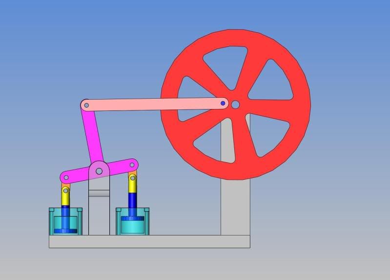
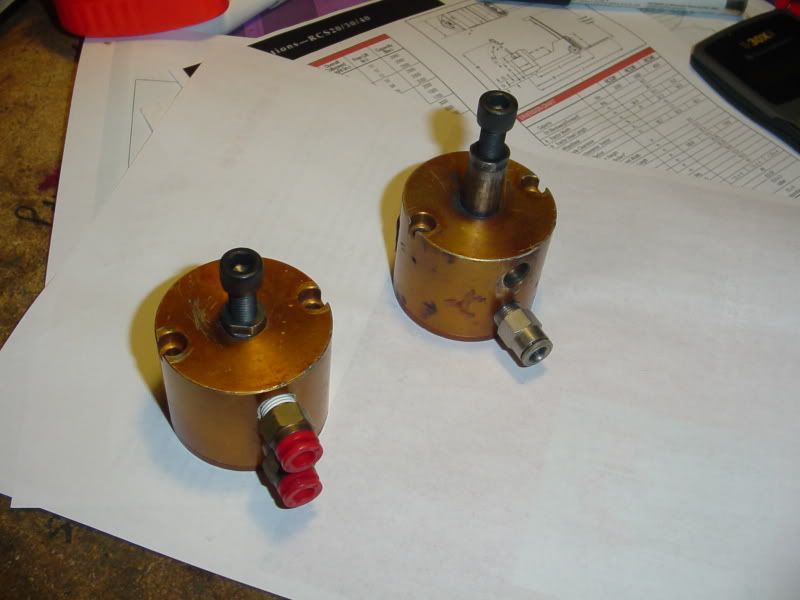
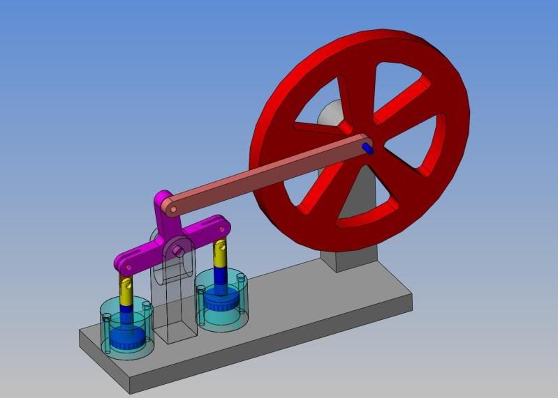
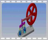
I have a couple of old short stroke air cylinders left over from a job I did a few years ago. They are 1 3/8" bore x 3/4" stroke. I got thinking the other day about using one of them to build a bell-crank actuated steam/air engine. The more I thought about it, the more I wondered "Why not build a double ended bell crank mechanism, and use both cylinders?" As one cylinder extends under air pressure, the other engine could be retracting under air pressure. This would give double the power, and the valving would still be relatively simple--the two lines running from the valve would split and go to opposite ends of the two cylinders. Only one valve would actually be required to run both of the cylinders simultaneously. This would in effect require a valve similar to the one on the beam engine I designed a couple of years ago, which had one double acting cylinder. --Only difference would be that instead of the valve bore being in the same block as the cylinder, it would become a "stand alone" unit with one constant pressure airline feeding it and two airlines leaving it which would alternate the flow to either the rod end or the cap end of a single cylinder---or in this case, each line would split to deliver air to opposite ends of the two cylinders. I spent a couple of hours "fleshing out" the design this morning. I haven't given any real design time to the valve, but did design and model whats been buzzing about in the back of my brain. Then of course, not being able to leave well enough alone, I animated the model and saved a video clip of the animation. Interesting concept, isn't it.----Brian
aircylinders002.jpg
 
Nice Brian,
When work does come your way.....You going say "na I'm to busy building model engines"
Good luck with the new design. Hope you find work or work finds you soon. Best of Luck!
Tony
 

Brian,

Simple design but makes use of what you have. Great thinking.

I compute the area of one piston to be a little less than 1 1/2 sq in so 5 psi ought to give you about 7 lbs of thrust from one cylinder, 14 lbs from two. At 30 psi you could have 90 lbs of force trying to move that T shaped rocker. Don't know the dimensions of your linkage elements but I can see where you could have a lot of torque applied to that flywheel.

I am guessing that with the apparent short offset of the crank pin from the centerline of the flywheel axle that this one is going to really whiz around. You might need to add a shrapnel shield to your design. :)

Have you calculated all this out or do you just take an educated guess at dimensions when you design an engine?

Thanks...
earl...
 
Brian,

Looks an interesting concept. I can't quite figure out the valve from your description, but I will keep watching and all will be revealed! It's the exhaust I'm struggling with.

Nick
 
Potman--I agree with your assesment of the short stroke demanding a high RPM which I would really like to avoid. I wonder if a person could "cheat" by having the vertical arm of the rocker beam twice as long as the other two arms going from the pivot out to the two cylinder rods. This would give a 2:1 ratio, so that although the pistons only travel 3/4 of an inch, the "outstanding" arm would move twice as far. This would then allow a 3/4" offset in the attachment point on the flywheel instead of the .375" offset shown in the model. Power would be lost because of the longer torque arm at the rocking beam at a ratio of 1:2, but then would be regained at the flywheel end because of the longer torque arm created there, so that in effect power output would remain constant, but speed would be cut in half?--It gets a bit mind boggling.
 
Brian, that would certainly be a good way of slowing it down a bit. I can't recall seeing anything like it so it's pretty unique :bow:
 
NickG said:
Brian, that would certainly be a good way of slowing it down a bit. I can't recall seeing anything like it so it's pretty unique :bow:

Somewhere lurking in the dingy recesses at the back of my mind is the picture of a pump that was set up almost exactly like that. Can't for the life of me recall the details tho'. :(
 
tel its dark back there u need to be carfull lurking around there : )
 
Brian
Not too far off a design I hope to build someday. The Bernay engine plans are not commercially available so anyone building it has to bruise a few gray cells figuring it all out. If you get brave, I'm first in line to mug you for a copy of shop drawings ....LOL

Steve

Here it is.... http://www.lindsaybks.com/gallery/Jorg/bernays/page2.html

Here it is modeled and animated.....

Bernay.gif

 
This is the same engine, modified as per my earlier post. I didn't bother to animate it, as the animations I am able to save thru photobucket are so short that they aren't of much use. However, I can "grab" the flywheel and spin it in realtime on my computer screen and make all of the linked parts behave exactly the same as they would if the machine were actually built. It does work exactly as I had anticipated. It seems that the way to run this engine would be with a very small "flow" of air, to keep the piston speed down.
ASSYOFBELLCRANKENGINE-version-2.jpg
 
Brian...
No, not one of mine, but since the owner felt compelled to abscond with one of my engine animations, I didn't feel too bad about borrowing his...(grin). I've modeled a number of projects, but haven't felt the need to animate any of them in a while.

Steve
 
Steve---How do you make an animation like the one you posted? I can save my Solidworks animations as a .avi file, which is HUGE and can't really be posted anywhere, nor emailed because its too darned big. I then use Windows Moviemaker to save my .avi file as a .wmv file, which can be uploaded to Photobucket, but will only run for a matter of a few seconds, not enough for people to follow very well. I assume that there must be proprietary software involved in making an animation like you posted, but I really don't know. I would love to be able to do that, but I'm not willing to spend money to purchase a program that has no "money making" potential for me.---Brian--edit--I see that the animation is called a ".gif" file, but thats a new one to me.
 
Brian....
It helps to be among the ancients of the internet...(grin). GIF files were the earliest types of image files that one could use on a web page. The first were static images rather than animations. Then someone discovered they could be saved in layers. The idea worked a bit like the old flip book animations once found in boxes of Cracker Jacks. A series of "advancing motion" images were digitally stacked and made to "flip" when loaded, giving the net its first method of animation.

In the earliest days it was a complex process requiring use of a cumbersome algorithm and you had to keep the file sizes quite tiny. A 50Kb animation could get you flamed for abuse of available bandwidth.... and that was just from your ISP.

Today the software is pretty much drag and drop and can be found free on sites like www.tucows.com . (see gif animators) You'd need to create each frame as a static image, (usually about 40 images will give you a small animation but many run to 150 or more these days) and use the software to organize them in order of movement. I usually save my images as bmp files (another antique format) and then convert them to static gif files.

BMP files use 16 million colors while GIF only uses 256 at a time. A bit of practice and one can simulate nice even colors without dithering (speckles). With more practice one can do a few timing tricks to produce some pretty cool special effects.

There are literally 1,000,000's of GIF animations floating around in uncounted libraries on the net. Most have been stolen and abused so often that they've come into the public domain by default. If you can't track down who's using your art work, then you pretty much lose control over its use. I've see quite a number of mine in use all over the web.

Back when it first became possible to create them, (around 1995) AOL paid me 17 grand to create a really nice one for an early Comdex trade show display. Then they managed to completely alienate me. Their brilliant IT guy never figured out how to use it on their large display screen.... LOL. Only one of several unhappy encounters I've had with that arrogant bunch.

Steve
 
Brian,

This one was made with a camera on a tripod and then 8 separate stills taken as the mechanism was rotated approx 45 deg between shots. Not very good but illustrates the process as you can identify the individual shots.


PISTONV.GIF
 
Maryak---that is a very interesting .gif, and it brings up a good question. Although I have designed and built a few engines, I still do not have a clear picture in my head about the valving on a double acting engine. I know that there is a set relationship between the stroke of the piston and the stroke of the valve, as well as a relationship between the port spacing and the length of the valve "large ends" and possibly even the length of the piston in the engine. I know that on the beam engine I designed, I copied Elmer verburgs relationships from his smaller beam engine, and it worked, but "Copying" them is not the same as understanding them. Without getting into a lot of arcane steam engine philosophy, I would love to be able to get a more thorough understanding of the valving as shown in your .gif----Brian
 
I struggle with valving. I'm looking forward to learning more about it in this thread.
 
I know that there is a set relationship between the stroke of the piston and the stroke of the valve,

This is where you are going wrong Brian - valve travel and piston travel are entirely independent of each other.
 

Latest posts

Back
Top