Double-Acting Twin Beam Engine Build

Home Model Engine Machinist Forum

Help Support Home Model Engine Machinist Forum:

This site may earn a commission from merchant affiliate links, including eBay, Amazon, and others.
Got started on the linkages for the parallel motion part of the mechanism, which guides the piston rod in a straight line from the end of the main beam.

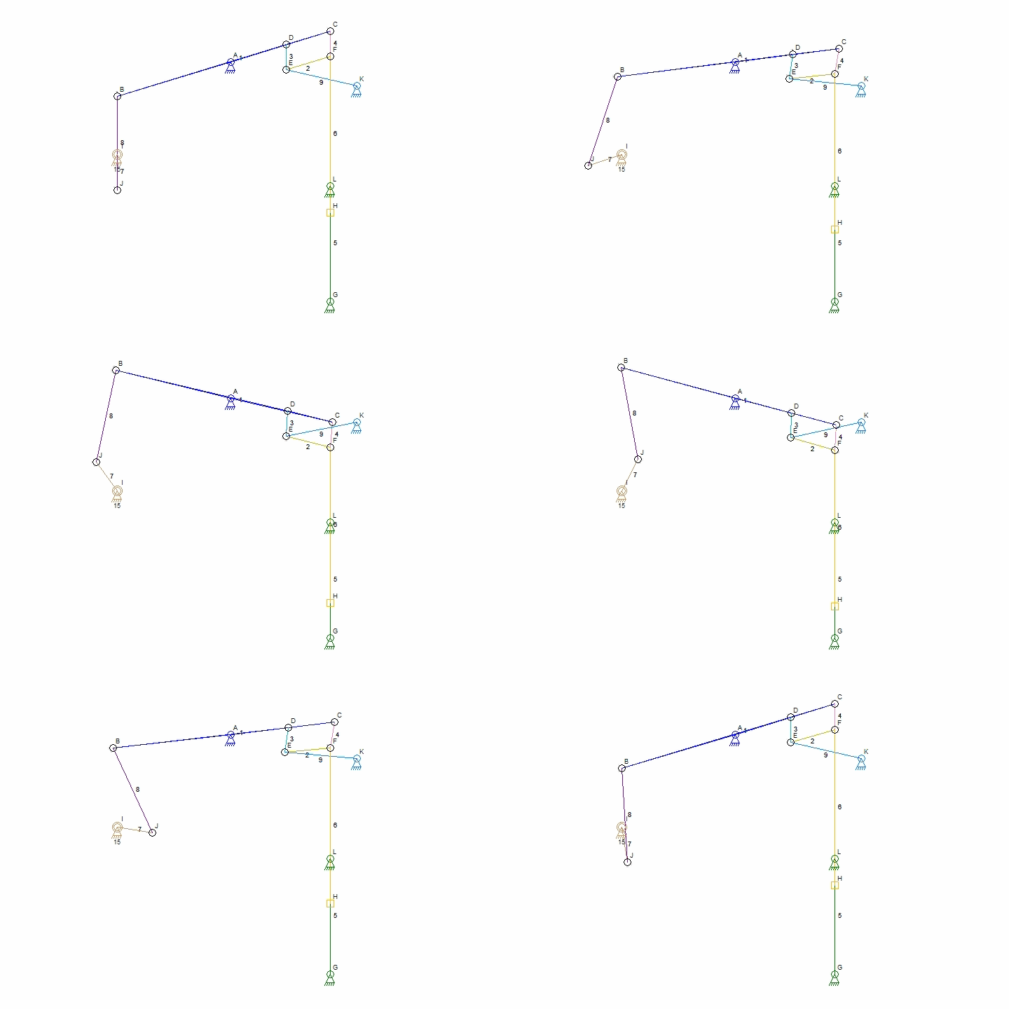
Here is a diagram of how the linkage works (thanks to wikipedia). The parts I am making now are labeled D-E, E-F, and E-K on this diagram. The bushing is what holds it all together at point 'E'.
Watt_Parallel_Motion_Simulation.gif


The parts for this are pretty straightforward, just a lot of them. To start out I'll make the link bars and the bushing that connects them:
scan_081.jpg

The bars will be pieced up from 3/8" dia. ends and 3/16" dia. rod. Since there are 12 link bars altogether it is definitely a case for mass production. Started with 3 lengths of 3/8" round steel, each long enough to make 8 ends. Drilled a 0.191 hole down the length of the rod, and then cross-drilled and tapped a series of 3/16-40 holes along the side (center drilled first, or main drill would skate off the curve):
IMG_3782a.jpg

The ends were then cut off, 0.200 thick. Made the rods from 3/16" bar:
IMG_3783a.jpg

and threaded/soldered the ends onto the rods:
IMG_3785a.jpg

Once all those were made (lot of the little buggers!), made the center bushings from 3/8" rod. The ends were turned down and shoulders threaded at the ends to hold an 8-32 nut:
IMG_3786a.jpg

Here is the first set together, showing the order the rods fit on the bushing and where the piston clevis will go in:
IMG_3787a.jpg

and both:
IMG_3788a.jpg

Next up is to make the shoulder bolts/nuts for the assembly, and get the parts hung on the beam. After that, need to make another support column set to hold up the forward link (at point 'K' on the diagram above).
 
Last edited:
Okay - got the rest of the parallel motion linkage done (ran out of 3/8" rod, had to get some more - amazing how much stock this engine has taken so far). Made up the shouldered bolts from 3/8 stock - first turned down the portion going through the links, then threaded the end 0.150, and cut them off. Several sizes were needed, for the different number of links they had to go through - all done the same way, just with a different length shank.
IMG_3789a.jpg

On the rotary table, milled in the hex on the end. In this shot, first two flats are done.
IMG_3791a.jpg

Final step - cut in a little shoulder on the end to dress it up a little:
IMG_3792a.jpg

All that just for a bolt....
IMG_3795a.jpg

Last parts needed for the linkage were a pair of columns to hold up the final links. These were made of 1/2" brass rod, tapered and fluted to go with the pattern on the central column. Here are the dimensions for the support columns:
scan_084.jpg

First, turned in some steps at the base:
IMG_3800a.jpg

and rounded that over into a bead with a file:
IMG_3801a.jpg

simaler thing at the top end, but cut in deeper:
IMG_3802a.jpg

Then, just like was done on the main column, offset the headstock to turn the taper on centers:
IMG_3803a.jpg

A cross hole was drilled halfway through the top section to hold the crossbar, and the bottom was drilled and tapped 8-32 for the screw to hold the columns to the base:
IMG_3804a.jpg

Finally got to bolt everything up and see how it looked. All went together okay, but it was looking a little chunky (good in a chocolate chip cookie, bad in an engine). So, went back and thinned down the clevises and the bolt heads. Also had to thin the spacers to match. After that, it was looking more in proportion.

So, here is the parallel linkages assembled:
IMG_3816a.jpg


Here are a couple shots of the progress so far (made up the wood base too - needed that to get it to lay flat, given the bolt heads underneath. There are shallow holes drilled in the wood so the plate will lie flat):
IMG_3815a.jpg

Later on, the aluminum base plate will be covered with a thin wood layer to make it look like a factory floor. The black-painted plates will show through the floor boards.
IMG_3821a.jpg

Looking pretty good so far, I think. Next up is to make the eccentric followers and the linkage bars for the valves. The bars will have a pattern like the main beam....
 
On to the valve eccentric followers. Here is a sketch of the dimensions for them:
scan_085.jpg

They are pretty standard, with the exception that rather than having a connection point in the top for the connecting rod, I will be running one rod from each side, running them down to meet at a point near the cylinder, with a pierce web between them to match the main beam (photos in next post showing that assembly).

To start, took some 1/4" thick brass flat stock, and milled in a step on either end:
IMG_3841a.jpg

then drilled 1/8" holes for the rods:
IMG_3845a.jpg

ran some bolts through the holes to clamp the pieces together and marked for the center:
IMG_3846a.jpg

and drilled a starter hole for boring out the middle:
IMG_3847a.jpg

With it mounted in the 4-jaw, it is too large to fit on the lathe (sherline), so rather than reset everything with the riser blocks, I figured it was just as easy to bore it out on the mill with the rotary table. Started boring out the center:
IMG_3848a.jpg

and all the way out to the 0.900 diameter that will form the ridge sticking out in the center, which holds it in place in the slot on the eccentric:
IMG_3849a.jpg

then set the cutter to be 0.100 down from the edge of the hole, and 0.050 out, milled one side out to the 1.000 final dimension:
IMG_3850a.jpg

That did one side of the ridge - now turned the piece over in the chuck, and recentered it again (could have used a keyway cutter on the original setup, if I had one...)
IMG_3851a.jpg

with it all centered up again, milled the matching step on the second side:
IMG_3852a.jpg

Here is a closeup of the ridge after milling (have not deburred it yet in this shot)
IMG_3853a.jpg

One down, same to do on the second follower:
IMG_3854a.jpg

With the insides done on both, rechucked them with one pair of jaws on the inside step, and milled down the outside, first on one side:
IMG_3855a.jpg

then the other:
IMG_3857a.jpg

Here are both follower sets, ready for the rods:
IMG_3858a.jpg

Thats all that the site will let me upload in one post - next will continue with the rods....
 
On to the connecting rods between the valve eccentrics and the valves. Since the distance is so great, it was either use a large diameter rod (too plain looking), or use a pair of rods, from either side of the follower, tapering in to meet near the valves. I saw the paired rod way done on some other engines, and liked the look, so I went with that style. The area between the rods will be filled with a pierced brass web, in a pattern to match the main beams. So, drew that pattern out on some sheet brass (left over from some clock gears), and started milling out the holes. I dont have any cnc setup, so it was back to etcha-sketch time on the mill table:. The sheet brass is clamped down to a scrap of wood to keep it off the mill table itself:
IMG_3867a.jpg

First set of holes done:
IMG_3868a.jpg

continuing on to the rest of the holes:
IMG_3870a.jpg

here are the finished web inserts next to the followers:
IMG_3872a.jpg

Threaded some 1/8" steel rod at the ends, for nuts to hold the followers together, bent them just below the threads to match the angle of the inserts, and wired them to the inserts to solder it up. Oh, and the top of the follower has a small notch filed in to hold the insert in place.
IMG_3874a.jpg

Here are the pieces so far all together. Still need to make a fitting at the narrow end, to connect it up to the valve lever:
IMG_3875a.jpg

Here are the rods in place on the engine (high-tech eraser to hold up he forward end for its portrait!)
IMG_3876a.jpg

IMG_3877a.jpg
 
Okay - got the ends of the valve rods made up. Started with a chunk of 3/16" steel long enough to make two ends (easier to hold), and drilled 1/8" holes in the ends, slightly angled to match the rod ends (drilled slightly oversize so they would go onto the rods - should have made them before soldering up the webs. Oh well, still worked).
IMG_3878a.jpg

Hacksawed out the center section and went to the mill to clean up the curves:
IMG_3879a.jpg

center cleaned up
IMG_3880a.jpg

and the two ends cut apart:
IMG_3881a.jpg

Then, drilled a 1/2" deep hole in the tip, and tapped it 5-BA:
IMG_3882a.jpg

Soldered the ends onto the ends of the valve webs, and made a couple short sections of 1/8" rod to hold the clevis at the end (clevis was made weeks ago when valve cranks were made). The rod was threaded both ends, and the clevis loctited on. the end of the rod where it goes into the end of the conn rod is threaded longer, and serves as the length adjustment.
IMG_3883a.jpg

Here it is all installed on the engine. The point labelled '1' adjusts where the connecting rod attaches to the valve crank, moving it up and down changes the ratio of the travel on the cranks, allowing for adjustment of the length of travel on the valve. The point labelled '2' is where the adjustment is made for centering the valve travel - threading that rod in and out changes the center point. Between the two I have all the adjustments needed without having to change anything in the steam chest itself, which is a pain to get at with all the other stuff around it.
IMG_3889a.jpg

And a couple more shots of the progress so far. Getting near the end of the build - still need to make the inlet and outlet manifold piping, and a needle valve for the inlet. It all cranks over by hand cleanly, and I can hear the air blowing in and out, so it SHOULD run well. Hopefully!

IMG_3885a.jpg

IMG_3891a.jpg
 
Great work, and it looks like on a Sherline?

Can you tell us a bit about the proportions of the parallel bar links? I know the 4 links must make a parallelogram but what is the relationship between the bar that 'grounds' them to the frame and the beam lengths? It seems to me this must all be very closely related.
 
Hi Ron,

Yup - I have a sherline mill and lathe.

The parallel linkage does have some important distances. Going from this diagram,
Watt_Parallel_Motion_Simulation.gif

the distance from A->D needs to be same as from E->K, and are best set to 1.5 times the stroke distance on the piston. Also, the D->E and C->F distances must match each other to form the parallelogram, and are best set to 2/3 the stroke distance. There is a good writeup on this at http://en.wikipedia.org/wiki/Parallel_motion
Its an interesting linkage - first time I've made one. Without it, I think I would have needed a longer connecting rod and a fixed guide - this way is much more fun to watch.
 
Down the home stretch - need to make the intake piping (just some tubing and blocks), and a needle valve to control speed on the engine. Here is the sketch for the valve:
scan_068.jpg

The body is brass - started with a block and bored in the end holes for the valve stem
IMG_3228a.jpg

and the counterbore to fit the tubing
IMG_3229a.jpg

the hole for the inlet - threaded to take an adapter to the compressor hose:
IMG_3231a.jpg

and a couple holes for screw mounting it to the base
IMG_3232a.jpg

Here is the body so far, with the compressor hose adapter screwed in
IMG_3233a.jpg

For the valve stem, offset the headstock on the lathe a few degrees to turn a taper on the end
IMG_3236a.jpg

then threaded the stem above the taper
IMG_3237a.jpg

and cut it off just beyond the thread. The shoulder there will act as a stop for the handwheel
IMG_3242a.jpg

Parts so far
IMG_3245a.jpg

Made up a quick handwheel - threaded same as valve stem
IMG_3248a.jpg

and loctited the handwheel onto the valve stem
IMG_3248a.jpg

Looked a bit blocky, so put in some steps, mirroring the shape of the internal passages
IMG_3252a.jpg

completed valve:
IMG_3253a.jpg

and it in place with the intake piping
IMG_3899a.jpg

Still need to make a block to hold up/support the valve body....
 
[SIZE=-1]Got the twin beam engine up and running - still have a spot where one piston is sticking a little at the top of the stroke so it is a little uneven still, but it runs quite slow on just a few pounds of pressure. Not bad for first run! Still need to make a support block for the needle valve and get it running smoother (fix that sticking point, tweak the valve timing a little more, it sounds like the right one is a little out still), but just could not wait to get it turning...! :D

[ame]http://www.youtube.com/watch?v=xgopmZu3pts[/ame]

[/SIZE]
 
Last edited:
That looks awesome with all those moving parts and the contrast of the brass and stainless


Jeff
 
[SIZE=-1]Got the twin beam engine up and running - still have a spot where one piston is sticking a little at the top of the stroke so it is a little uneven still, but it runs quite slow on just a few pounds of pressure. Not bad for first run! Still need to make a support block for the needle valve and get it running smoother (fix that sticking point, tweak the valve timing a little more, it sounds like the right one is a little out still), but just could not wait to get it turning...! :D

http://www.youtube.com/watch?v=xgopmZu3pts

[/SIZE]
Beautiful job, I'm really impressed.

Dave
 
Did some more running on the engine, and tweaked the valve timing some more, it is starting to smooth out. There is still a slight hitch in the travel at the top of the stroke on the right piston, but that is wearing in - think it mainly needs some more running in. Sigh, just have to run it more! :D

Got some shots of it next to the last engine I made, a miniature double acting beam engine. Looks really small next to its big brother!

IMG_3916a.jpg

IMG_3911a.jpg

And the engine by itself:
IMG_3914a.jpg

IMG_3913a.jpg

Here is a new video of it running, bit smoother than the first one, still needs a little more run-in on the right side. I think that side was the first one I lapped, and did not do enough on it (was concerned about bell-mouthing the ends, and apparently was too conservative on the one end). It runs well at higher speeds, and will go down so slow that the flywheel is not really doing anything, and you can see it speed up/slow down as it switches back and forth from running on 1 piston/2 pistons/1 piston again at the top/bottom of the strokes.
[ame]http://www.youtube.com/watch?v=pYgt7npWCMM[/ame]
 
Well done Crueby! Your engine is very beautiful and watching running is really facinating. You can be very proud.
 

Latest posts

Back
Top