DIY electronic Z-axis zero setter

Home Model Engine Machinist Forum

Help Support Home Model Engine Machinist Forum:

This site may earn a commission from merchant affiliate links, including eBay, Amazon, and others.

Majorstrain

Well-Known Member
Joined
Dec 24, 2008
Messages
304
Reaction score
4
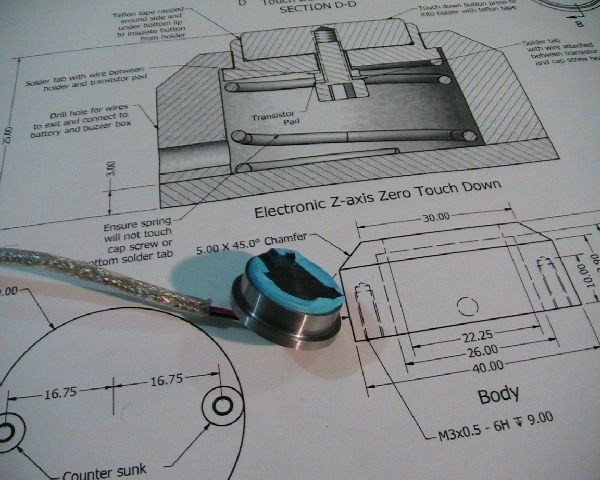
This is a small off shoot from making the QCTP. You how it goes, make a tool to make a tool to make a project. I'm waiting for the dovetail cutter anyway.

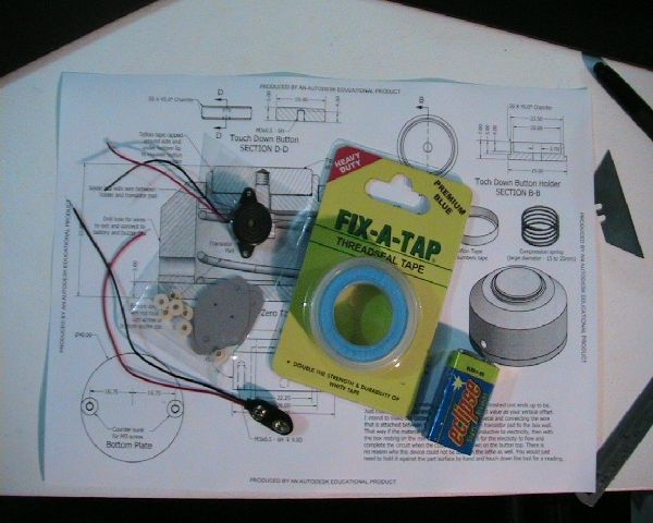
The electronic parts and cost under $10 and the spring I got from an auto shop for $2.50. All the steel is of unknown grade out of the scrap box, you could use ali for all but the top button.

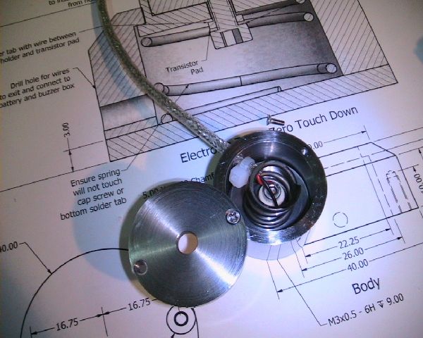
I changed the body size 35mm on mine because that was all I had. The consequence of the reduction was to use M2 screws to hold the base on instead of M3
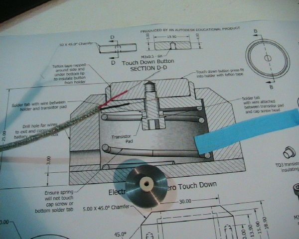
The Teflon plumbers tape is thicker than the standard but you can use whatever you like. The drawing also mentions a solder tab but I didn't need them in the end, I just wrapped the wire round the screw.

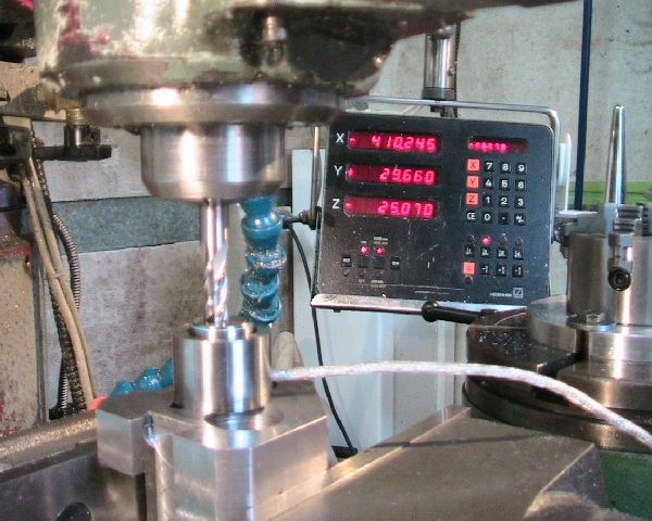
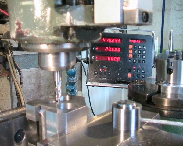
The final height does not have to be accurate, all you do is measure it and use that figure as you z-axis offset. Mine turned out at 25.08mm

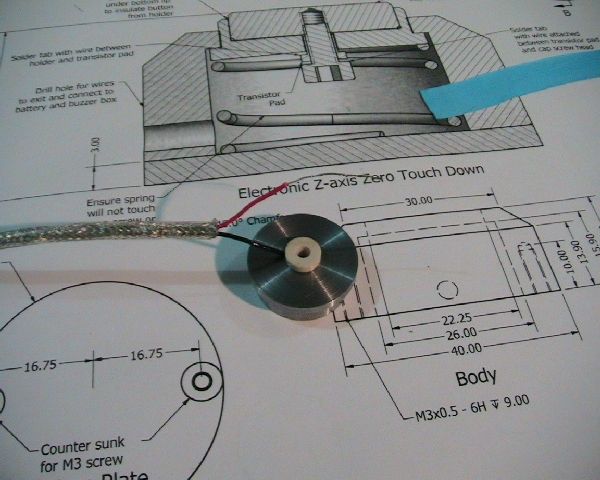
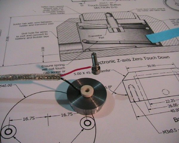
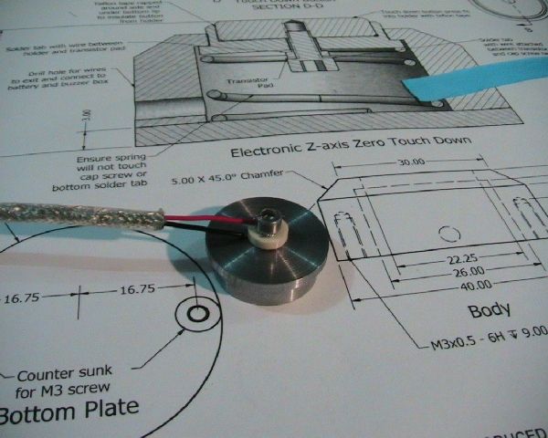
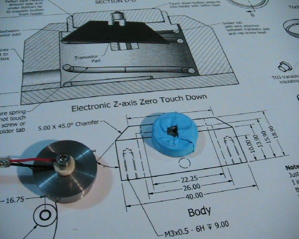
Here is the drawing for the project

Enjoy
Phil

stand by for pics.

View attachment Z-axis zero.pdf
 
Here are the assembly pics, I didn't take machining pics because it's all standard stuff.
If something is not clear just ask and I'll mock up the set-up for you.

IMG_0634.jpg


These are the parts,
The buzzer is a 3 to 15 volt DC type
The pack with the grey and white bits are a TO-3 transistor insulating kit. You only want one of the white bits (insulating sleeve)
The plumber thread seal tape is 0.1mm thick (not critical)
The other parts are a standard 9V battery and a battery snap.

IMG_0632.jpg


This is the spring I got from the auto store, it was 100mm long and had a diameter or 15mm. I is quite stiff.

IMG_0633.jpg


I heated and cut it at 20mm and then bent it to form a flat bottom and ground the base level.
The springs free length ended up to be 15mm long and the cavity space is 12.9mm so there is a bit of force on the button holder when assembled. This is what you want.

The following pics are the assembly steps

IMG_0635.jpg


The wire was and old USB cable that I cut the ends off and used two out of the four wires.

IMG_0636.jpg


The black wire is sandwiched between the button holder and the insulating sleeve cap.

IMG_0637.jpg

IMG_0638.jpg


The red wire attached and seated

IMG_0639.jpg


The top button wrapped with one layer of Teflon tape. Use two or more layers if you have the thin tape.

IMG_0640.jpg


The button installed in the button holder. I ran a blade around the tape to trim off the excess.

IMG_0652-1.jpg


The inside view as assembled.

IMG_0645.jpg


Finished the assembly. now to show the wire connections.

IMG_0651-1.jpg


Well that's it

Cheers
Phil

Oops, forgot to explain how to use it.

Just sit the Z-axis zero setter on top of your part and raise the mill knee or lower the spindle until the stationary cutter contacts the button top. when contact is made the buzzer will sound. Then just set your DRO to minus (or plus, depending on your DRO) the height of the Z-axis zero setter and use that as you offset above the job.

Note the Z axis DRO readings
IMG_0654.jpg

IMG_0655.jpg


It could be used on the lathe as well, but you would have to hold it in place on the part face with you hand while you touched the tool tip to it.
The button is spring loaded so if you contact it with a bit too much force, it won't get damaged.
 
This may be a realy dumb question but how is contact made inside . I am not quite seeing how this works.
Tin
 
Tin Falcon said:
This may be a realy dumb question but how is contact made inside . I am not quite seeing how this works.
Tin
Hi Tin
There are no dumb questions, if 1 person is asking then 20 other people are thinking it. Thm:

There are no contacts inside. The Teflon tape forms an insulator between the two wires and the metal they are attached to. The electricity requires another path to flow and make the buzzer sound. This other path is the body of the mill or lathe itself.

The contact is made (or for a normal circuit the switch is closed) by the cutter or tool tip through the machine body. (mill or lathe)
When the cutter touches the top button of the zero setter the circuit is completed and the buzzer sounds, without the cutter touching the zero setter the circuit is open and the buzzer is silent.

The path the electrical current takes from the battery is through the red wire to the top button of the zero setter, from there it flows through the cutter and machine body to the machine table and part to be machined.
It then flows through the zero setter base to the button holder and back through the black wire (note below) to the buzzers red wire, from the buzzer it flows back to the battery in the black wire.
So in effect there is no moving contact inside the zero setter. The only moving part is the spring and its only job is to absorb the pressure of the cutter touching down too hard.

The correct offset reading is taken when the buzzer just starts to sound on application of the cutter.
If the spring has been compressed by the cutter touching down too hard, the the reading is taken when the buzzer stops sounding on withdrawal of the cutter.

Note: If you're machining a non-conductive material like PTFE of PVC the the current can not flow back through the part being machined. to get around this I mounted my buzzer and battery in a metal box (jiffy box) and connected an extra wire to the point where the black wire from the button holder and the buzzers red wire are connected. Then I connected that extra wire the the metal box. So as long the metal box is resting on the machines metal surface somewhere then there is a return part for the current to flow.

Sorry for the long winded reply, I hope I've covered it.
Cheers
Phil

ps the above explanation assumes conventional current flow theory as opposed to electron flow theory. Rof}
 
Now I see said the blind man LOL
The button is one contact it is insulated from the body the body the other contact the mill is the switch. Where is the blinky L.E.D for those who can't hear the buzzer.
Realy I do like this project and will likely buiild one for the cnc mill.That is after I tranlate to american LOL.
Thanks
Tin


Thanks for the comments and questions Tin,
That is after I tranlate to american LOL.
Thanks
Tin
Google translate does a pretty good job. ;D ;D ;D Rof}

Cheers
Phil
 

Latest posts

Back
Top