cut & rejoin gear in half

Home Model Engine Machinist Forum

Help Support Home Model Engine Machinist Forum:

This site may earn a commission from merchant affiliate links, including eBay, Amazon, and others.

Rayanth

Well-Known Member
Joined
Jun 7, 2011
Messages
338
Reaction score
7
Greetings all, I'm a new member but I'm sure I'll be around for a long time.

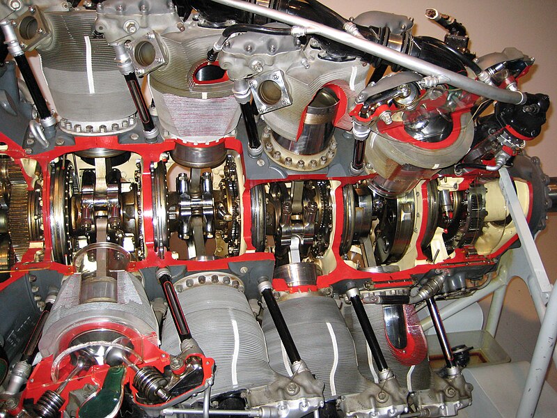
I am presently without a workshop and a little rusty on machining skills, but my CAD skills are rather fantastic, and I have been putting them to use in a new scale model engine design. The engine I am scaling as a very interesting crankshaft which has three gears attached to it in locations where they can't simply be slipped on. The full scale version solves this by piecing together two halves of the gear over the crankshaft into one full gear. I am not privy to the method which they managed to reattach it.

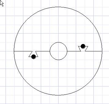
In trying to determine how I would be able to do this at about 1/6th scale, I can only devise two methods. One would be to simply machine the gears in as part of the one piece crankshaft, but I have no experience with cutting gear teeth... the other method would involve splitting two identical gears in such a way that they have a tongue and groove to rejoin them, with a press fit pin going through the join. Two gears would have to be used, due to material removal while cutting it in half, removing too much of a tooth to maintain a consistent gear when rejoined. The cuts on each half would be offset to get a true half, taking into account the cutting blade/bit.

Can anyone think of another way of accomplishing this tricky task? I am sure there are ideas that I have missed, either in cutting or in rejoining...and as these are the gears that drive the cams, I am keen on ensuring they are quite accurate.
 
Rather than use two gears cut the joint in two separate pieces of metal, join together and then cut the gear from these. That way you will have no cut so no loss of metal.

Jason
 
The two gears method was aimed more at avoiding cutting the gear teeth myself, as I'm not familiar with that process. I figured I could just get two gears from Boston or somesuch, and carefully index and cut, as mentioned.

If I'm going to cut the gears myself, would it be easier to do it in halves as you suggest, or just machine them right into the crankshaft from its blank?

I see two issues with machining it into the crankshaft directly but my experience is again limited. One is that it would be the same material as the crankshaft this way- steel, which I don't suppose is really bad as it should up to wear better...but if it DOES wear down, then I have to machine a whole new crankshaft instead of just the gear....hmm. Thoughts?
 
I'll endorse Jason's suggestion. It makes much sense in your application.

Assuming they're simple spur gears, making them is straightforward and there are plenty of folks here who can help you to get the job done.

Alternatively, a redesign may simplify things. How about a picture showing the gears and an explanation of why they need to be an integral part of the crank.
 
Without pictures it's a little hard to understand fully but...................

Maybe a built up crankshaft is the way to go and the gears are slipped on before the crankshaft is assembled.

Hope this helps.

Best Regards
Bob
 
I can think of a way to make a gear in two halves....but the why is missing...PICTURES please?

Dave

 
This iI don't have pictures immediately available, as I am at work. Tomorrow I can post the pic from their patents, but it doesn't show the gears integral. Perhaps I can mark up their locations

I suppose more info on the project in general can't hurt and could lead to other input.

I am attempting, ground up, a 1/6th scale working model of the Pratt and Whitney R-4360 Wasp Major. This was a 28 cylinder Radial in the form of 4 rows of 7 cylinders. By necessity, the cam gears for the middle two rows, which equates to three cams, must be mounted in the middle of the crankshaft. The crankshaft's design simply prevents one from sliding the gear in from the ends, there's just no clearance, as you'll see when I get the pic posted tomorrow. I was hoping to get the crankshaft machined as one piece as in the fullscale, I think getting the high precision irrational number degree offsets for each throw would be very difficult if machined as a multi piece, but I have been wrong before =)

I'm starting to warm to the original idea of machining the gear from a blank as two joined pieces, I can see how it would ensure the teeth aren't messed up, and would certainly be easier than my other two options
 
I'm starting to warm to the original idea of machining the gear from a blank as two joined pieces, I can see how it would ensure the teeth aren't messed up, and would certainly be easier than my other two options


That would be the way I would proceed. That will be tough enough.

Dave
 
Rayanth,
If you can purchase ready made gears, I would cut them in half, as you described, but I would clamp the halves to the shaft and silver solder (4%) them together and to the crank. I don't think you would need to silver braze them.

Jeff
 
After a brief discussion with a mechanical engineer at work (always nice to have ready access to one of those), he failed to make a suggestion for the gear but brought another question to mind- if I have to put gears in the middle of a one piece four throw crankshaft then I have to put bearings there too.

I'm reassessing the devotion to maintaining a one piece, and possibly splitting it into a multi piece, now.
 
Split bearing are very common you don't have to reach for the nearest available ballrace.

Soldering anything to the finished crank could risk distortion.

Cutting the gear into an integral part of the crank risks mucking up a lot of work should you cut one of the gears wrong.

Jason

EDIT
I think I can see the gears in there somewhere :eek:

800px-Biggest_rotary_cutaway.jpg
 
Whilst I don't like the idea of a split gear it can be done.

You can split a stock gear via wire cut EDM from root to root (for an even number of teeth this would be straight across the centre - for an odd number a slight dog-leg in the cut.

You can then shim the gap - may not be required depending on how you mount it.

You obviously run the risk of getting the tooth to tooth pitch across the split slightly out - this will be a noisy and detrimental problem

Ken
 
In my minds eye, the split gear would need to be machined after spliting for registration pourposes.

The ID would need to be matched to the shaft EXACTLY otherwise the PD would be off and you would run
the risk of incurring an angular pitch error. Having said that it may be prudent to spline the ID of the gear to the shaft to maintain angular pitch alignment Then there is keeping the two halves together with some shrunken ring or something....

Hmmmm....any other ideas?

Dave
 
This is one way to do it;

Dovetail two pieces of material together and install grub screws on the joint line.

Drill bore and ream centre hole

Turn outside to correct diameter.

Takes a bit of careful work, but nothing really difficult about it.

splitgear.jpg
 
Thats it Tel....do the dovetails all in one set up (male and female) on both pieces.

Then drill/bore/ream. Then turn the OD.

Dave
 
HI the dovetail way is brill I have dun gears that way myself but looking at the pic i think it may be hard to put the gear on the crank as it dus not look as ther is plenty of room for the dovetails to be sild back in to place
 
If the ID of the gear is the same as the OD of the crankshaft, there will be no change in the gear teeth when the two halves are clamped to the shaft.

I would make the cut with a .010 slitting saw and then fill the gap with 45% silver solder when the gear is in place.
 
I guess the real question is if the original crankshaft one piece or did it have some sort of Hirth joint between the sections?
 
The dovetail idea is similar to my tongue and groove idea, only in the other direction. the tongue and groove thought was to machine down 1/3 of each face, just past the dividing centerline, and then a 1/3 thick groove in the opposite. doing this for both sides of the split gear would let them nestle inside each other without interfering with anything. a press fit pin going through the joint tongue/groove on each side would prevent it from coming out. Both may be feasible.. but I'm now starting to wonder if it might be better to do a multiple piece crankshaft.

I'm attaching a picture straight from the patent application for this engine. I have made a few marks - red lines where the gears would have to be split to be installed, and blue lines where split bearings would be needed for the master rod journals. The other side of this picture shows how the Master Rod journals are offset 192.85... degrees from each other. Row 'A' (top of image) is in the rear of the engine.

I don't believe I need to use dynamic counterweights, from my understanding the second and third order vibrations should not be an issue at the smaller scale. So I'll have solid counterweights in place of the bifilar type they have on either end of the crankshaft.

If you're curious about other details, the patent number is also visible... it's really a marvel of engineering to get 28 cylinders working in harmony in a radial.

crankshaft.jpg
 
Rayanth said:
I don't believe I need to use dynamic counterweights, from my understanding the second and third order vibrations should not be an issue at the smaller scale. So I'll have solid counterweights in place of the bifilar type they have on either end of the crankshaft.
But it wont sound like a Pratt unless it clunks when you turn it over. ;D

It's quite probable the gears are just screwed to bosses machined to the crankshaft forging. No real need to do anything special on the real one, scale screws into that part of the crank are probably not going to happen. I have some pictures of the cutaway myself, the one from the Yankee Air Force museum before the fire. Shame its probably a pile of slag scooped up with the rest of the hanger ashes. I will dig around tonight when I get home to check if I have any better views of the gears.
 
Back
Top