Centering piston bore on mini mill - not enough Z clearance for indicator

Home Model Engine Machinist Forum

Help Support Home Model Engine Machinist Forum:

This site may earn a commission from merchant affiliate links, including eBay, Amazon, and others.

Tater

Member
Joined
Feb 28, 2012
Messages
20
Reaction score
0
I have the piston bore held in the vise on my mini-mill. With the DTI that I have, there is no where near enough room between my chuck (or 3/8 collet - tried that too) and the work to insert the DTI to find the center so that I can drill the cover plate holes around the circumference. This is on the Elderberry launch engine.

Is there another method that I can use to center the bore in the vise? Otherwise it looks like I may have to spring for a smaller DTI - mine is a cheap-o model that is tough to use on the mini-mill.
 
Tater,
You might try machining a plug that fits the bore, with a concentric spigot to chuck on. You should be able to make this tool compact enough to center the bore. Getting a chuck and drill bit in the limited space could be another problem.

Good Luck!
Daryl
 
Tater,

Make up a short spigot that is a nice sliding fit into the bore, with a tiny lead in taper, and turn another smaller spigot onto the end of it that fits your drill chuck.

Mount your cylinder nice and square into your vice, with the spigot in the chuck.

It is then just a matter of moving your table in the X & Y until the spigot is a nice sliding fit in the bore when you pull down on the feed handle.

I use this method all the time to locate pre drilled holes when using my mill, but I normally use transfer punches instead of making a spigot tool.

Using this method, you are never more than a thou away from perfect alignment, but you must make sure you spigot is a nice fit into the bore.


John


Aligning spigot.jpg
 
Tater said:
I have the piston bore held in the vise on my mini-mill. With the DTI that I have, there is no where near enough room between my chuck (or 3/8 collet - tried that too) and the work to insert the DTI to find the center so that I can drill the cover plate holes around the circumference. This is on the Elderberry launch engine.

Is there another method that I can use to center the bore in the vise? Otherwise it looks like I may have to spring for a smaller DTI - mine is a cheap-o model that is tough to use on the mini-mill.

Hi,

I use a slightly different method with an edge finder. Just rough center the piston. Move the table in the Y axis in any one direction till the edge finder finds one edge, zero the dial or better still the dro. Now move the Y axis in the opposite direction till the edge finder finds the opposite edge and note the distance, now move the Y axis again in the other direction exactly 1/2 the distance that you noted and lock the Y axis. Repeat for the x axis and where you end up is exactly in the center of the piston..

It all takes about a minute

Regards,

A.G
 
Don't use the vice, clamp it to the table which may give you the extra depth you need. Will depend on the size of your vice.

J
 
Thanks for the help everyone. I think I'm going to turn a simple plug & spigot as it seems a simple and elegant solution, and it will be pretty much dead-on.

The problem I see with the edge finder approach is that the circumference of the cylinder is pretty small, (1 inch dia.) and it would be easy to miss perfectly perpendicular X and Y coordinates when locating the edge.

However - I think I'll actually do both and compare the results.

John - thanks very much for the drawing :bow:- made me realize that sometimes the simplest solutions are often the hardest to find in a workshop stuffed with more complicated options.

Jason - you might be right - I think there could be enough room if I were to clamp directly to the table and put the DTI in a collet - clamping would be very tricky tho as I need access to the full top face of the cylinder for drilling the cover holes, then have to flip the part and repeat on the other side. If I use the vise, it will be a little easier to reposition the part.

Thanks again everyone!
 
can't You center and drill the covers, then spot the holes on the cylinder?

Marcello
 
Tater,

I forgot to add that you need to turn the large spigot first for say double the length required, then turn the smaller one to fit into your chuck. Then part off.

That ensures that they are both concentric with each other, then just use a small file to put the tiny feed in taper on the end of the large spigot.

BTW, I too would use Jason's method as well, but unfortunately, I have both vice and RT mounted onto my table, and I would have to take one or the other off to do it as Jason says. But at times, that is the only way I can do it if I have a really thick component to machine.


John

 
Take off the vise, since you are only drilling holes, two holdowns should be all that needed. It would take less time than typing your post and reading the answers.
 
But if he didn't post then everyone else would miss all of the excellent techniques.
This forum is my machining class. I hope people never stop posting questions or techniques.
Best
Stan
 
Sshire said:
But if he didn't post then everyone else would miss all of the excellent techniques.
This forum is my machining class. I hope people never stop posting questions or techniques.
Best
Stan

Amen to that brother! Thm: Thm:

Ron
 
I for one am very thankful for the experienced ones here who do post the "method" as it's just about the most important thing you can post on these projects. Often the lessons here are what we carry into our own projects and falls within the mantra of "Each one Teach one"

If there was ever a "philosophy" on this board....this concept is on the short list!

:bow:

Dave
 
I for one am very thankful for the experienced ones here who do post the "method" as it's just about the most important thing you can post on these projects. Often the lessons here are what we carry into our own projects and falls within the mantra of "Each one Teach one"
If there was ever a "philosophy" on this board....this concept is on the short list!
Aye - aye :bow:

Kind regards, Arnold
 
Ok, so the centering operation turned out to be the easy part. I used two methods - first was the plug method - turned a simple plug as shown in Bogstandards drawing and had the cylinder centered in about 20 mins. Works quite well - but turning the plug did require a lot of test-fit to the cylinder to ensure accuracy.

Second was removing the swivel base from my milling vise, squaring it up to the mill, then using the DTI in a drill chuck. I think this is the way to go for repeatability and speed. But now I have a couple of new skills under my belt, and I'm beginning to learn how to think around challenges with a broader set of possible solutions to choose from..

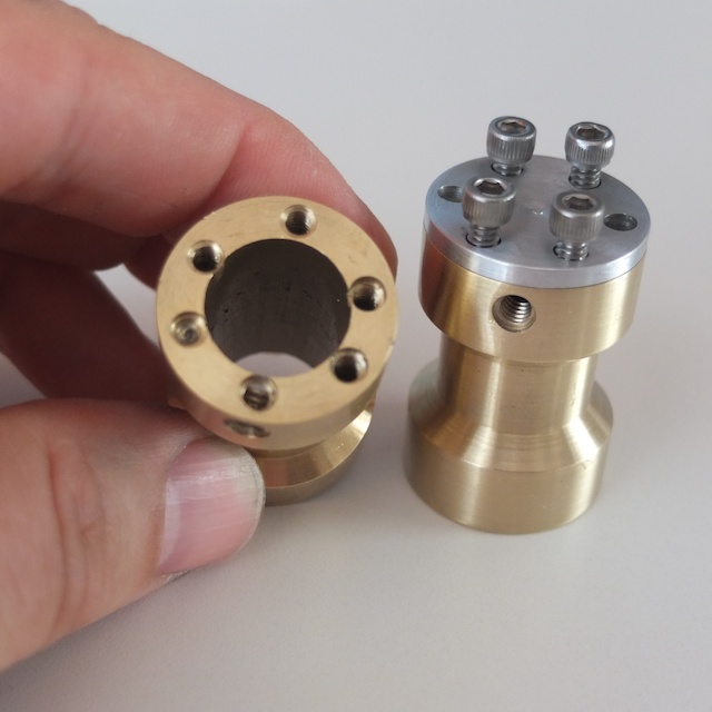
Anyhow. No matter that I was able to center the cylinder under the spindle - the next challenge was to drill and tap the top and bottom bolt rings. Well.... feeling rather confident after my centering victory, I decided to rely on the X2 mill graduated dials to find my drill centers. So I proceeded to dial-in, center drill, tap drill, tap and repeat - I did all of this through the cylinder cover, (as the directions suggest) so I was not able to check the bolt ring directly on the top face of the cylinder. Well.... I was most unpleasantly surprised to discover my results - upon removing the part from the milling vise after my carbide center drill broke off in the very last hole!! Not only were the holes improperly indicated - I neglected to alleging the part properly and ended up drilling and tapping directly into the cylinder port. ::)

So, I've lost all confidence in using the dials on the X2 alone to find my way. I think there is too much slop, backlash and just plain inaccuracy in the mini mill to rely on the dials as they come factory finished. I'm thinking a DRO or even CNC conversion may be in the cards if this machine is to be used with repeatable accuracy?

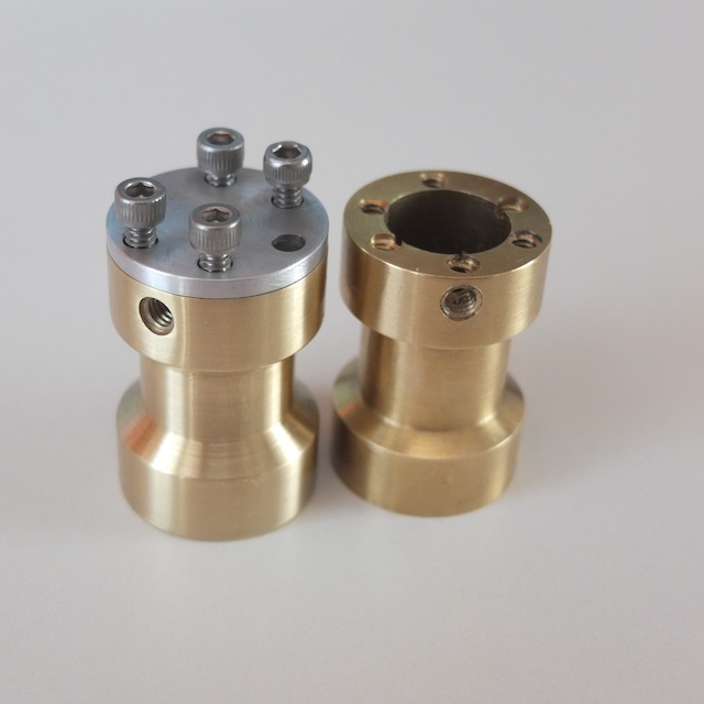
So, after destroying one cylinder, I turned up a second, made the cylinder cap and this time, used a dial height gauge and to scribe the parts - then used the pointy center finder to locate under the mill. This time - not absolutely perfect - but within acceptable, (first engine) tolerance I think. Thm:

Results below:

DSCF0760.jpg

DSCF0763.jpg
 
Tater said:
The problem I see with the edge finder approach is that the circumference of the cylinder is pretty small, (1 inch dia.) and it would be easy to miss perfectly perpendicular X and Y coordinates when locating the edge.

Not necessary to find the exact center of the circumference relative to the X or Y travel. Just eyeball it in X or Y, find edge, raise spindle and move table so opposite side of workpiece can be accessed, lower spindle and find the other edge. Divide by two to find the middle. Do the same for the other direction.
 
Tater, your photos are some of the best I have seen on here. What camera you using? Any specifics on lighting, tripod yes/no.

Thanks,

Ray
 
ironman said:
What camera you using? Any specifics on lighting, tripod yes/no.
Thanks Ray,

I do have some professional training and experience but these photos are strictly poin and shoot with available light, hand held. No tripod.

My camera is the fairly new Fuji X-10. It's pretty good with the macro. I think I could have done much better with a smaller aperture for more depth of field and a slowe shutter speed, but that would require a tripod!

Always glad to try to answer any photo related questions.

Thomas
 

Latest posts

Back
Top