Casting Restoration

Home Model Engine Machinist Forum

Help Support Home Model Engine Machinist Forum:

This site may earn a commission from merchant affiliate links, including eBay, Amazon, and others.

PolskiFran

Well-Known Member
Joined
Dec 7, 2007
Messages
61
Reaction score
0
Part 1

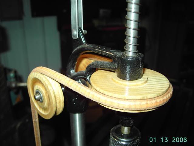
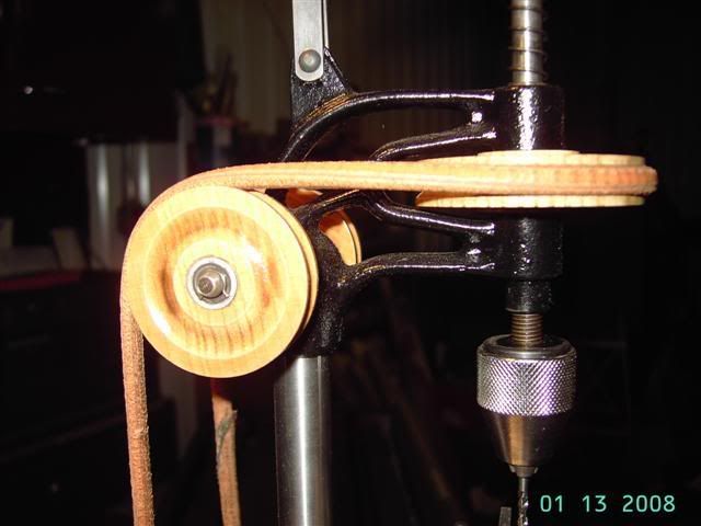
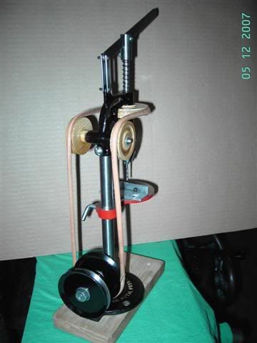
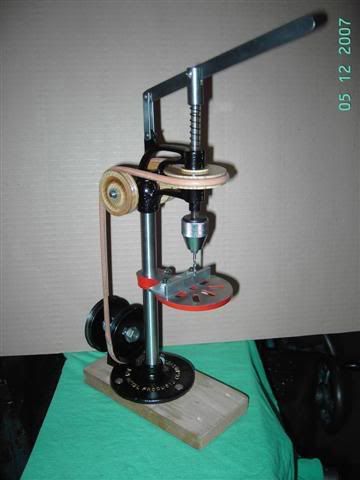
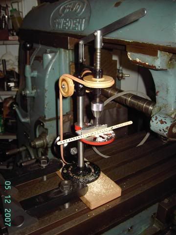
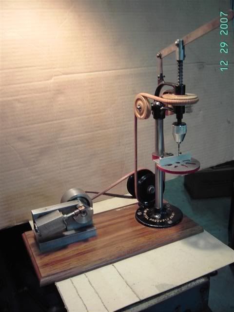
I have had a few requests to post more pics of my small J&H drillpress. I thought I would post the pics of the restoration process that I went through on this project. Some of this information may be useful if you are going to restore one of the "original" antique engines, or if you are looking to put one of your small engines to "work".

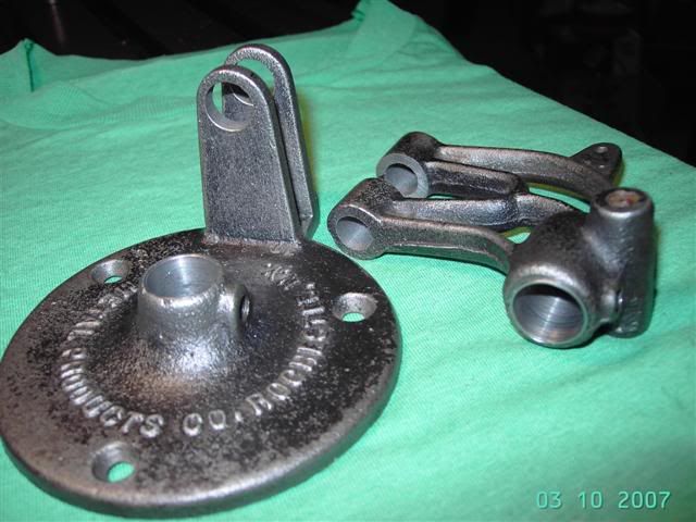
The drillpress was manufactured by J&H Metal Products of Rochester NY. I believe it was produced sometime between the late 1930's to early 1950's. This is the type of drill that was sold to the home machinst / hobbyist of that era. They were probably sold through advertisements in Popular Mechanics type magazines of that time.


JHDrill003Small.jpg


JHDrill001Small.jpg


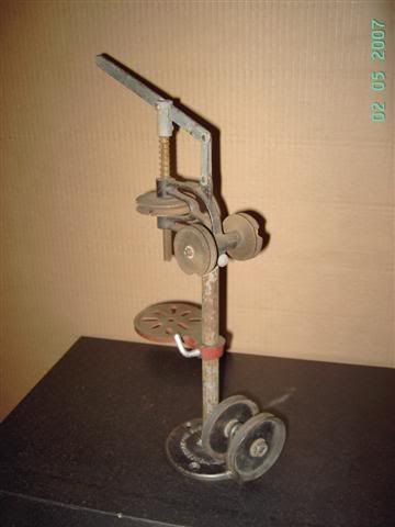
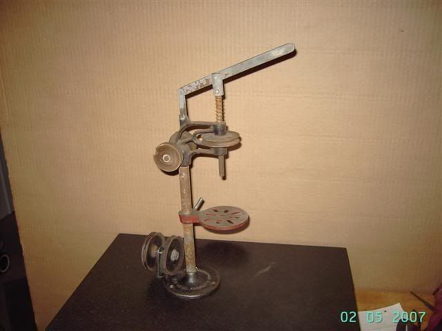
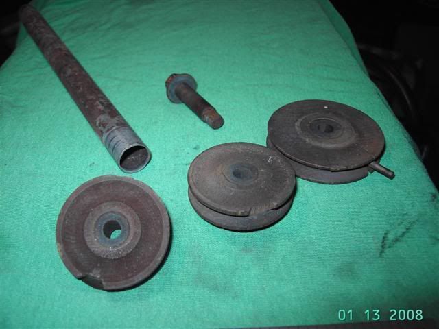
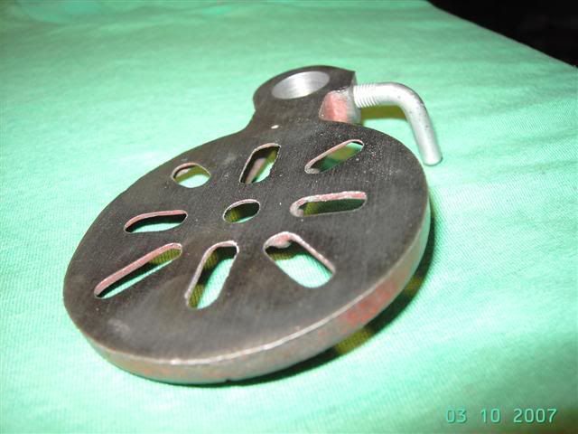
The drillpress was purchased at a swap meet for $1.00. At this point it was rusty, corroded, dirty, and bent. Every joint and shaft wobbled and there were chunks missing from the wooden pulleys.

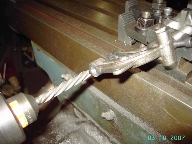
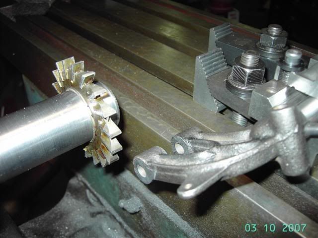
I put penetrating oil on all the joints and screws and disassembled everthing carefully. The screws were removed by loosening 1/4 turn then tightening 1/4 turn to work the rust loose and reform the threads on the screw ends. The rivets that held the quill feed lever and linkage were carefully ground off at the peened end with a dremel grinder. All the removed parts were put in a box for safe keeping.

Frank
 
Frank were you wearing a mask when you bought that for $1.00
or was it a bold robbery? LOL

What a find!!!!

Rick
 
I didn't realize that the pulleys were wood? You don't see that very often anymore.

Wes
 
Dang! When I find something like that, the people typically want $10,000 for it. I'd say you got a great deal!

Definately keep the referb up here. I like seeing old things make a come back!
 
Part 2

Clean up of parts:

After the complete tear down it was time to clean the parts. The head, table and base are cast iron. Some of the sections of the casting have very thin cross sections in them, no rough handling here. I wire wheeled the castings to get most of the dirt and off. In the areas that were hard to reach I used a small wire hand brush and scrapers made from old hacksaw blades and old files.

Side Note: I often use a scraper made from an old file to clean larger castings. Using the scraper takes off the high spots created by the sand used in the casting process. This makes for a smoother surface to finish paint, while still retaining the look of a casting.


JHdrill007Small.jpg


To give you a little prespective on the size of the machine, the base has a diameter of 3 7/8" with a 5/8" hole for the column. The head has a quill / spindle dia. of 5/16".

You will notice I did not remove all of the paint from the castings. I figured if it adhered for the past fifty years, it will probably last another fifty. It did not present any problems in the refinishing, but if there are lumps, etc. in the old paint it would be best to get it all off using some form of paint remover.

All the original shafts for the drill, even if I didn't reuse the shaft, were polished in the lathe to remove any rust dirt, etc. Use a small hand wire brush to clean threads, keyways, snap ring grooves, etc.

The pressed steel pulleys for the drill are a two piece design, the halfs sandwich together to make one pulley. I mounted each half on the original shaft and cleaned them with 220 grit emory to remove the old paint and clean the rust.

The feed lever, linkage, screws and nuts were lightly wire wheeled, then I used a scotchbrite pad by hand to finish. It was amazing that the original plating still held.
Correction: The plating was in very poor condition. It completely went away when they were wire wheeled. The scotchbrite did make a nice finish on the bare metal.

Frank
 
This is great! Those are some nice looking castings. What did it have, if any, for bearings?

Wes
 
Part 3

How Much Repair Work is Needed?

I checked over all of the parts to see what had to be replaced, repaired or redesigned.

The original column had to be replaced. It was a piece of thin wall plated steel tube. It had quite a few dents where the set screws had been tightened a bit to tight. This was replaced with drill rod.

The base casting had a sloppy 5/8" hole drilled to mount the column. I figured I could use the next size larger metric drill rod (16mm)to remove the play. This would only require a light boring cut to finish to size. The main drive shaft bearing surfaces were worn considerably. The steel shaft rode directly in the casting. A good bearing surface if it would have been oiled. A new shaft and bronze bushings for the main drive pulleys would also be needed here.


JHdrill008Small.jpg


The 3" dia. table had an almost on size (16mm) column bore. A perfect fit with just a light polish. A light facing (flycut) would also have to be taken to put the table drilling surface back to perpendicular of the column.

The head would have to have a light bore taken out of the column bore too. The 5/16" dia. quill / spindle also rode in the casting (no bearings or bushings). There was a lot of play here and would have to be rebored and bushed with bronze bushings. These would be longer in length and stick out above and below the casting to give a little more wear area for the spindle. The keyway for the spindle pulley acted like a single flute cutter and oblonged the bore. The jack shaft seemed to be out of square to the column also. Another rebore job. Make a new stepped down shaft for the jack shaft pulleys.

The wooden drive pulleys would have to be replaced. There were just too many cracks and pieces missing. The pulleys rode directly on the shafts (wood to steel),the bores were completely worn out. The new pulleys would have to have bushings installed.

Miscellaneous Stuff:

A keyless chuck (old style, or something close) would have to be found or purchaced.

New belting for the drive system would be needed. I thought about using the urathane round belting but decided on using the original style round leather belting that was used on the treadle (foot powered) sewing machines.

The feed lever, linkage, thrust bearing and spindle cap could all be reused, unaltered.


Frank
 
Great stuff Frank. It looks like the table is about 4" in diameter? On the base piece, is that bracket part of the casting? Kind of hard to tell.

Thanks:O) Wes
 
Answering the questions:

Been extremely busy this week. I try to answer the questions that have been asked.

Rake. The guy was glad to get rid of it. It was half buried in a tool and "stuff" pile he had spread out behind his pickup at the swap meet. I almost missed it. After tearing everthing apart and seeing how much work was needed, I wondered who had the mask on ;D.

Powder. I was suprised to that the pulleys were wood. The originals were painted red. It does seem odd the wood was used on something produced during this time. Pressed steel was the norm.

WarEagle. I have never seen one like it, but my dad saw one go for sale as part of an auction box lot for about $5.00. They are out there. Keep your eyes peeled.

Powder. The quality of the castings is extermely good. No sand pockets or holes, except for one in the thin section of the table. This only came out after remachining it. The machining that was done at the factory was another story. Everthing must have been drilled with dull cutters and badly sharpened drills. Everything that was machined had to be remachined.

The table diameter is 3".

A few notes:

The drill press has a 4" dia. capacity. It measures 2 1/8" from the column to the centerline of the spindle.

Height to the top of spindle is 14"

The table dia. is 3".

The Base dia. is 3 7/8" with a 5/8" hole for the column. The stands for the main drive shaft are part of the base casting. It is about 1" from outside to outside and about 3/16 thick x 3/4" wide (each).


Thanks for the intrest in this project.
More to follow.

Frank


PolskiFran said:
After tearing everthing apart and seeing how much work was needed, I wondered who had the mask on ;D.

Thanks for the intrest in this project.
More to follow.

Frank

LOL
Now if it had been in perfect condition and needed nothing, would it have caught your eye? ;)

I for one am VERY interested in this project of yours, and
appreciate your sharing of it's progress here.

I'm anxious to see more on it!

Rick
 
I'm with Rick here, I cant wait till the next installment ;D ;D ;D That drill press is looking great!

Wes
 
Part 4

Machining

I started with the base casting. The bottom of the base had high spots along the outer ridge. I lightly ground the bottom on my belt sander until I had full contact for mounting.

JHDrill17001Small.jpg


The base was mounted to my fixturing plate with strap clamps to bore for the new column. A light cut was taken to fit the 16mm dia. I then found out the original bore was balooned in the middle and the new column wobbled. (I should have measured a little more carefully. The base was turned over and bored for a thin wall bushing (.015 wall thickness). If you look carefully at the bore on the base in Part 2, (the pics were taken after being machined) you will notice a difference in material at the top. I only bored to a shoulder to leave the original casting at the top. The bushings were made from CRS to a light press fit in the base while having a slip fit for the column. A +.001" than base bore on the O.D. while having a +.002" bore to accept the column after being installed.

The main drive bearing bores went very well. I set my fixturing plate vertical in the vise and clamped the casting after centering the both bores by using a piece of 5/16" drill rod through the bores as a guide. Fortunately for me I had a good side in each one of the bores to locate from. I bored to 1/2" to accept bronze shoulder bushings. A new 3/8" shaft was made. It was threaded at both ends with flats on the threads for driving the pulleys.

The head casting had to be bushed for the column in the same way. I used the spindle bore to locate from, and held the casting in the vise jaws.

JHdrill006Small.jpg


The spindle had to be reworked also. After the column was bushed, I held the casting with the column in V-blocks on the horizontal mill. I didn't have a long enough boring bar to reach the 2" depth needed. I improvised and used a long end mill and a slow feed. Using an endmill to bore gives a slightly oversized hole. I'm glad the bronze bushings are oversize. They were a light push fit, so a little locktite was used to secure these. After checking the total travel of the spindle I decided on using bronze bushings longer than the original cast area. This gave more bearing surface for the spindle and did not detract from the original appearance.

JHdrill005Small.jpg


The inner faces of the spindle sections had to be faced. They were very rough, and had a slight mismatch at the part line of the casting. I machined these using a milling cutter on a stub arbor. The spindle drive pulley rides here. A steel bushing was made for the pulley to be a slip fit between these faces.

The hole for the jack shaft was also rebored using a long 5/16" endmill. The new shaft was stepped down to 1/4" on each end with grooves to accept the "hairpin" clips that are used to retain the pulleys like the original.

The table was held by a stub of 16mm drill rod in a v-block and jacks at the other end to flycut the drilling surface. Even with adjusting the speeds and feeds I was still left with a chattered surface. I worked to the best machine finish I could get then sanded to final finish.


Frank


Looking good Frank! I appreciate your efforts here. Some of those settups are good. Using parts you just bored to locate others. It helps newer people see what can be done.

Thanks, Wes
 
Part 5

Wooden Pulleys, Spindle and Chuck


JHDrill23Small.jpg


The old parts.

The original wooden pulleys were completely beyond repair. I made new ones to the same dimensions as the original. I did make modifications to the new one for longevity sake. The new pulleys were made from ash wood donated by an old baseball bat. Thanks to CCW Ken from the HSM board for the tip on using wood from a bat. I tried to use a reamer for the bores in the pulleys, but this did not work very well. the holes came out oversized and not on center. The reamer wandered wherever the wood was the softest. I ended up drilling 1/8" undersize and boring with a boring bar to -.002" of the desired size.

JHDrill19Small.jpg


The idler pulleys are 1 3/4" dia. I used K&N brass tube for the bushings here. The tubes were pressed on to an arbor and lightly straight knurled to keep them from rotating in the wood. I know it isn't the correct material for the job but it was the proper size and it was on hand from another project. I think with proper lubrication they should give reasonable service.

The spindle pulley is 2 1/4" dia. A CRS bushing was used here. The bushing again was straight knurled and pressed into the bore. The spindle has a 1/8" keyway for driving from the pulley. The original pulley had a 1/8" pin driven through the pulley to act as the drive key. I decided to make a pin / key. The wood was drilled to the major dia. of a #8 screw and the bushing was tapped for 8-32. The screw was made using drill rod with the end milled flat for the key, threaded for the bushing, with a solid dia. to drive from the pulley, and slotted at the end for screw driver tightening.

JHDrill18Small.jpg


I needed a keyless chuck with 5/16-24 thread to match the spindle. I compared the chucks on my old "hand crank" drills, but nothing was a match. I used a 1/4" capacity keyless chuch from Harbor Freight. It had a 1/4" hex shank for quick changing with screw driver bits. The chuck was disassembled and the back section was bored in the lathe to .276" (letter I drill), and tapped 5/16-24. The chuck was reassembled and threaded on to the spindle. This worked just like the original. It would be my best guess that this drill's original capacity was 1/4"

Frank
 
I think I want to put wooden pulleys on all my stuff:O) Those look Awesome! Is there a bearing or something that pushes on the end of the spindle? I don't understand how that part works, from the pictures so far.

Thanks again, Wes
 
Part 6

Finishing and Assembly

The castings were cleaned with lacquer thinner and let dry. All of the areas that I did not want painted were masked off, or plugged with newspaper.

For masking to an edge, I let the masking tape extend over the edge, press down for a good seal at the mask area, and use a file to "cut" the masking tape to the edge. An exacto knife also works well in confined areas.

All of the parts to be painted were hung by pieces of wire, so all sides of a part could be painted at one time. A good coat of red spray primer was applied to all parts. I used gloss black spray paint for the finish color, 2 coats of paint covered well. The paint was purchased at the local Pep Boys auto parts store. This was their store brand and has always held up well on my other projects.

The lettering on the casting was painted with Testor's gold color model paint, using a very tiny brush.

The pulleys received 2 coats of polyurathane varnish. I made sure the varnish seeped in any gaps between the steel/brass bushing and the wood for extra grip.

Assembly went well as all mating parts were test fit as the machining was taking place. A few places had to be polished out to remove any paint that had seeped beneath the masking. The pulley bushings were installed in the base, the new shaft /pulley assy. and column.

The table was installed on the colmn making sure the locking screw had the bend below the table surface when it was fully tightened.

JHDrill013Small.jpg


The head was attached to the column. The spindle drive pulley was placed between the head bosses and the spindle slid through it. A little adjusting of the key/screw in the pulley was needed to get a smooth working quill. The feed handle was instaled next. The top of the spindle and the inner face of the return spring cap, where the down feed handle is attached, have a slight dimple on the ends to accept a 1/4" steel ball. This acts as a thrust bearing when the handle is pushed down. The cap is held in place by a round head screw that tightens on the outside of the cap, while allowing part of the screw protruding inside the cap to ride in a groove in the spindle. This keeps the spindle from falling down when lifting the feed handle. The linkage from the casting to the feed handlle is secured with round head rivets with grooves to accept "E" clips. The original had peened over rivets.

JHDrill011Small.jpg


The jackshaft pulleys were installed with thin washers and the original hair clip retainers.

I purchased the 1/4" round leather belt at my local sewing machine repair shop. McMaster Carr also has this type belt. I used a "scarf" joint to attach the ends of the belt. The end of the belt was ground at an angle. I ground from a sharp end to 1/4"diameter over a 1" length. This gave enough surface area for a good glue joint. I used "Shoe Goo", shoe repair adhesive to bond the joint. Do one end of the belt first, then snake the belt through all the pulleys, and mark the length allowing for the overlap in the joint. Cut to length, grind end, glue, clamp joint and let dry overnight.

The new belt was very stiff. It had a hard time bending to the contours of the small pulleys. I needed to make a "break-in" fixture to soften the belt. I used my fixturing plate (see Part 4) and fitted it with small pulleys and rollers using 5/16" shoulder screws (1/4-20 thd.). I snaked the belt through the pulleys and drove the belt with my slitting saw arbor in the vertical mill. It took at least 1hr. of running time to get the belt soft enough.

JHDrill009Small.jpg


I made a drilling guide from some aluminum angle to drill wooden coffee stirrers. A 1/8" screw machine drill was tightened in the chuck. I test ran the drill using my horizontal mill as power to get things broken in.

JHDrill014Small.jpg


After the break in, I mounted the drill to a wooden base and used my wobbler engine as power. Now I take it to the shows as an operating display. Yes. These little engines can produce power to do work.

I hope this may help someone who is attempting to restore an old piece of equipment. I tried to keep the machine as original as possible but make changes to improve its performance and operating longevity.

Thanks,
Frank
 
Frank,

I have been just a lurker on your project and I must say you have done a fine job with the restoration. To have a little engine powering the drill is first class. Thank you for taking the time to show how you did it.

Kenny
 
Rake, It would have attracted me if it was shiny, but the guy would have wanted too much for it. I'm a sucker for a piece of rusty iron at a cheap price :).

1Kenny, Thanks. I hope the this might help someone in the future. It isn't the machine, but the steps and processes in the restoration and repair. I'm trying to have all of my engines powering something. That way I don't have to answer the question "What does it do besides sit there and run?"

Frank
 
Thanks so much for posting this. I think I have enough to go on now. Is there a bearing where the leaver pushes against the spindle? I don't juite see how that part works.

Thanks, Wes
 
Back
Top