Metal Mickey
Well-Known Member
- Joined
- Jul 5, 2008
- Messages
- 612
- Reaction score
- 6
I am not sure if this is the right heading for this new tool build but I suppose I am modifying the electric motor......forgive me if the subject area is wrong........
Carbide tipped saws have been recommended for metal work in the past, especially when they are slitting saw size. In the UK I couldnt find a supplier of small blades but a HMEM forum member (from Canada) sent me some blades to try. There are some really nice people in the model engineering fraternity. I am sending a traction engine book back to Canada (as soon as it comes back into Amazon stock!) but thanks are in order.
Instead of just trying the blade in my slitting saw arbor I thought I would bring forward an idea I had about building a saw table. The reason I wanted to trial the carbide tipped saws was to cut a round bar in half so I can make two crankshafts for the Seal build. Since the camshafts have now been made the next major item for the Seals is the crankshafts, so you can see all roads in fact led to the saw table.
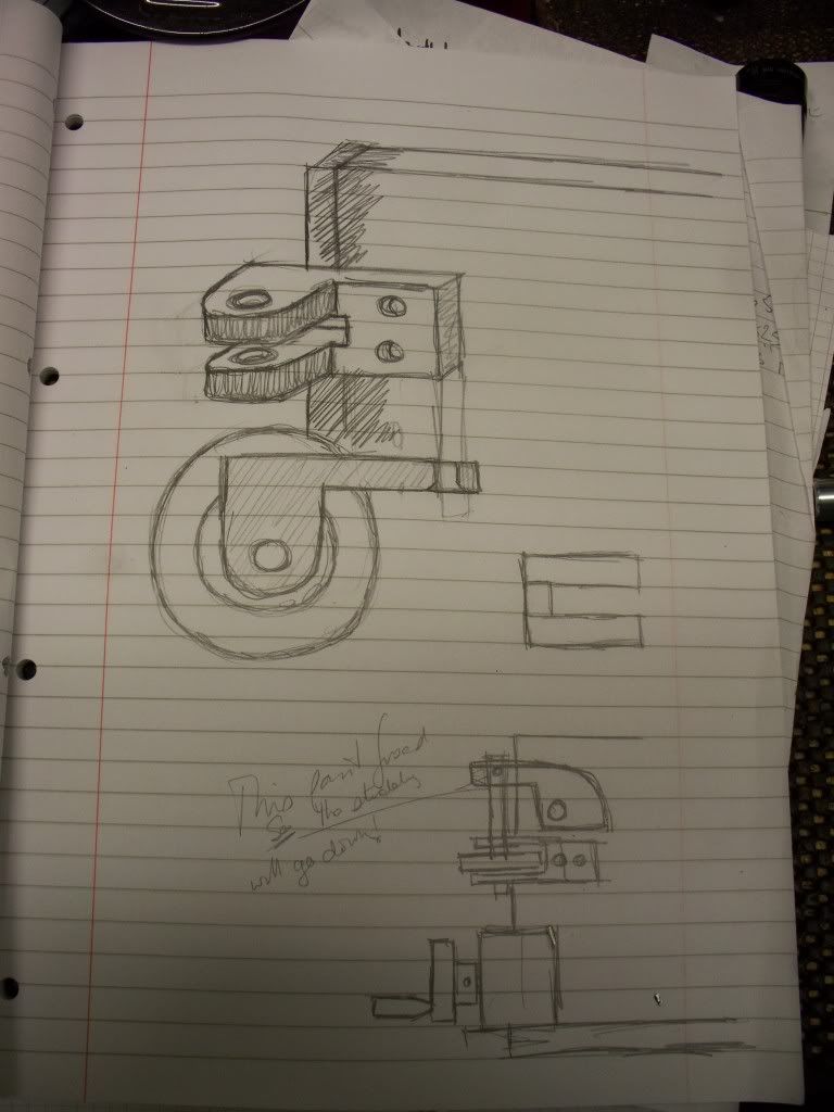
Since I dont sleep very well I often ponder designs during the night, scribbling down some drawings at my 0600ish breakfasts. I started by writing out the design criteria at one of these breakfasts, with the aim of making some CAD drawings, leading to a set of plans (Alibre) which could be made available on my website. So this particular project covers many areas of interest for me. Such as making a workshop tool, using CAD, and helping with the Seal twin engine project. Not a bad result really.
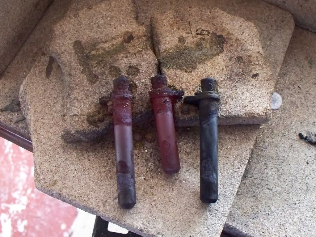
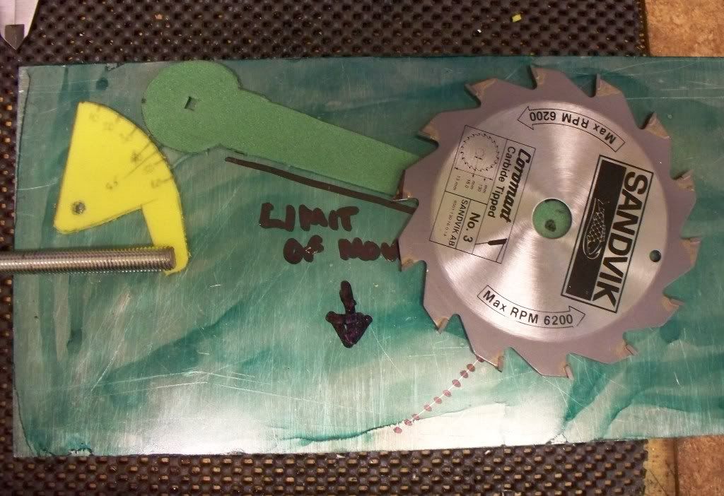
The design criteria covered such things as having two blade sizes (please see photos) so it would be useful to be able to use both blades on the same machine. The blade depth of cut should be adjustable and by a measured amount. The top should be as adaptable as possible, allowing the safe holding of materials. The blades should have some form of safety guard and make use of an existing electric motor I have.
Other ideas will no doubt come up as I progress, especially in the area of the work holding. I dont feel confident enough yet to just draw the design out in 3D CAD. Rather it will be a bit of both, build and the use of Alibre CAD. The help in laying out the plan I used some foam rubber/plastic as a former to check the size of the saw arm and the quadrant. By using these materials in a mock up I discovered my initial quadrant lever would not work so a new shape was soon cut out and tried.
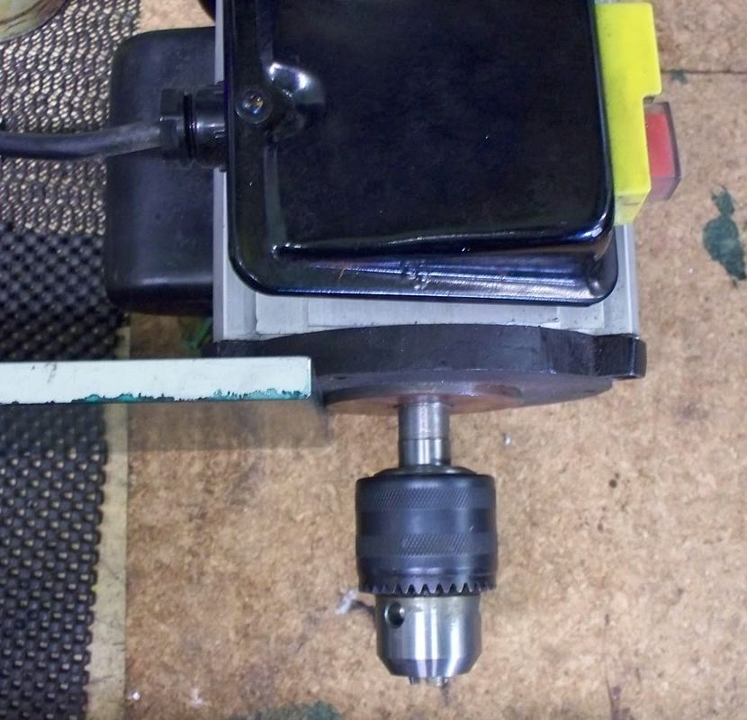
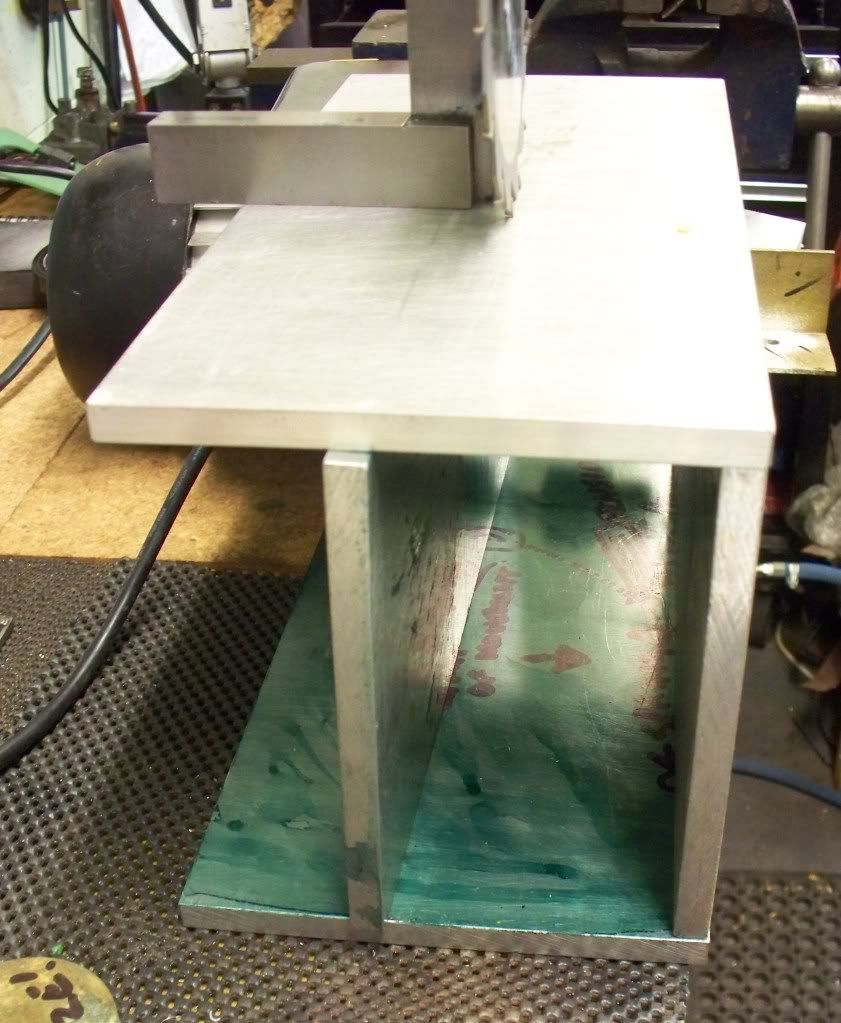
Since I have several ¼ (0.250 or 6.35mm) sheets of aluminum recovered from my local scrap yard I wanted to use these to make a strong box shaped saw table (please see photo).The first task was to check the speed of the electric motor. I have a rev counter which measures revolutions from model aero engines and made up a temporary shaft to hold the Mills propeller. The measured speed was approximately 1200 rpm. The saw blades run at around a maximum 6000 rpm so I needed to increase the speed from the motor.
I had a look at the spare gears from the Myford and there were both 20 tooth and 65 tooth gears that can be used. That should give me around 4,000 to 5,000 rpm at the blade. With these speeds I decided that all pulleys will have bearings and it was whilst searching for bearings I saw a diamond grinding wheel that would also fit the design. So I ordered the bearings and the diamond cutting wheel.
Now the project has turned into a versatile saw and grinding table which longer term I would also like to develop to grind camshafts in the future. Madness you may say (and you may well be right!) but if you take the saw table top as a base for holding various fixtures, then it should be an ongoing (maybe years) development for my own tool centre.
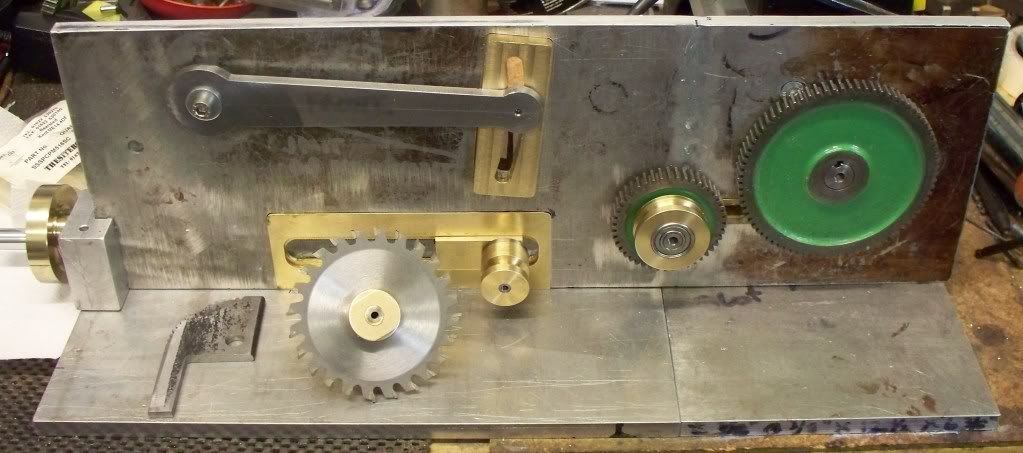
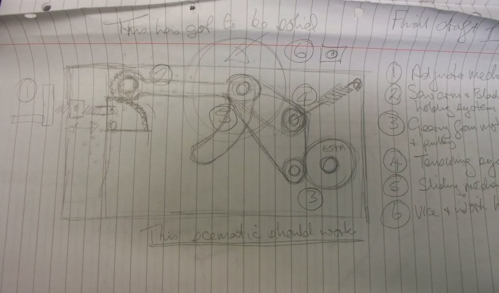
The rough design schematic is shown in the photo below to help you understand where I am going. To make the blade/grinding wheel adjustable I will use a quadrant with teeth cut into it, matching with teeth on the saw/grinding wheel arm. With the screw thread used for adjustments I should be able to make fine and measured cuts. Since this movement involves the arm then the pulleys will need to have a tensioning system to take up the difference.
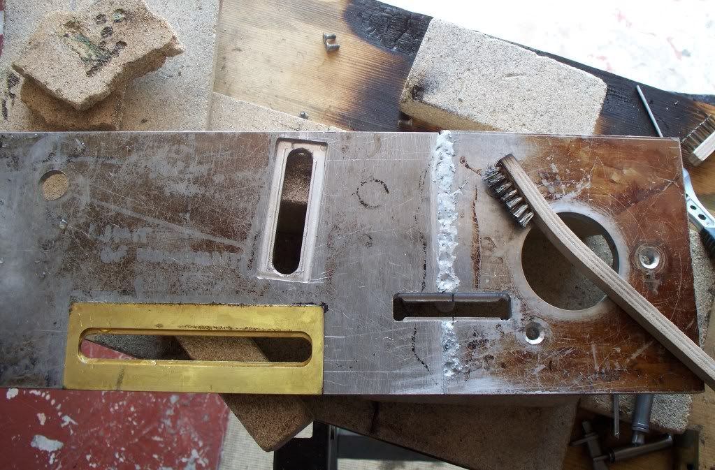
Since I hope to have the tool for many years I will also be looking at the materials used, for example the saw arm needs to have a guide and clamp to secure it when any adjustment has been made. Just cutting through the aluminum wouldnt really serve long term so I am letting into the plate a brass section (made from two lengths of square bar silver soldered together).
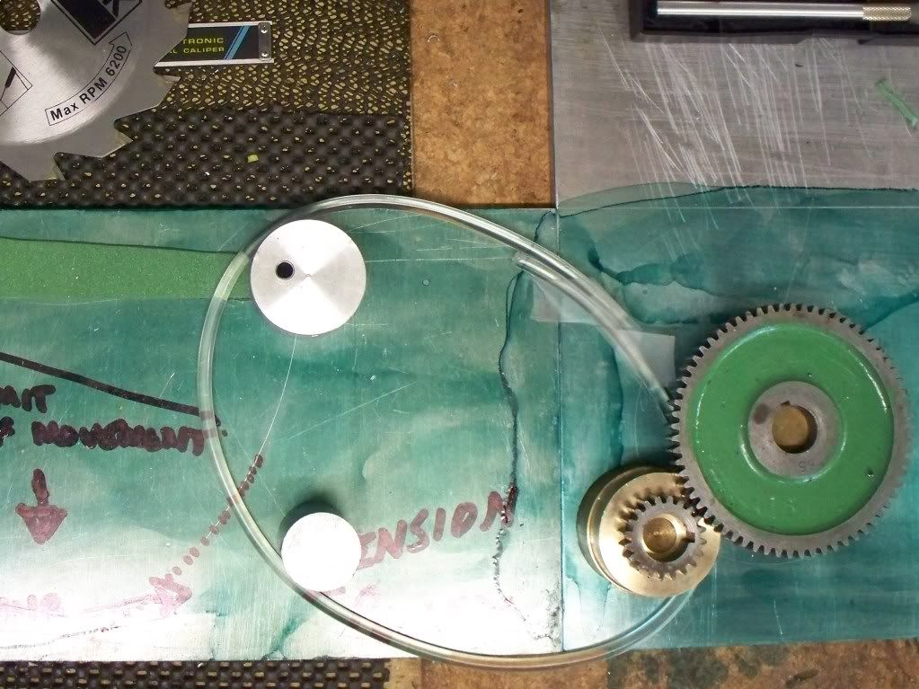
The drive belt I shall be using is circular in cross section and the two ends are welded together (see photo), access to the belt as well as the gears (in case I need them on the Myford) and saw/grinding wheel needs be incorporated for change of belt, blades or now the additional grinding wheel.
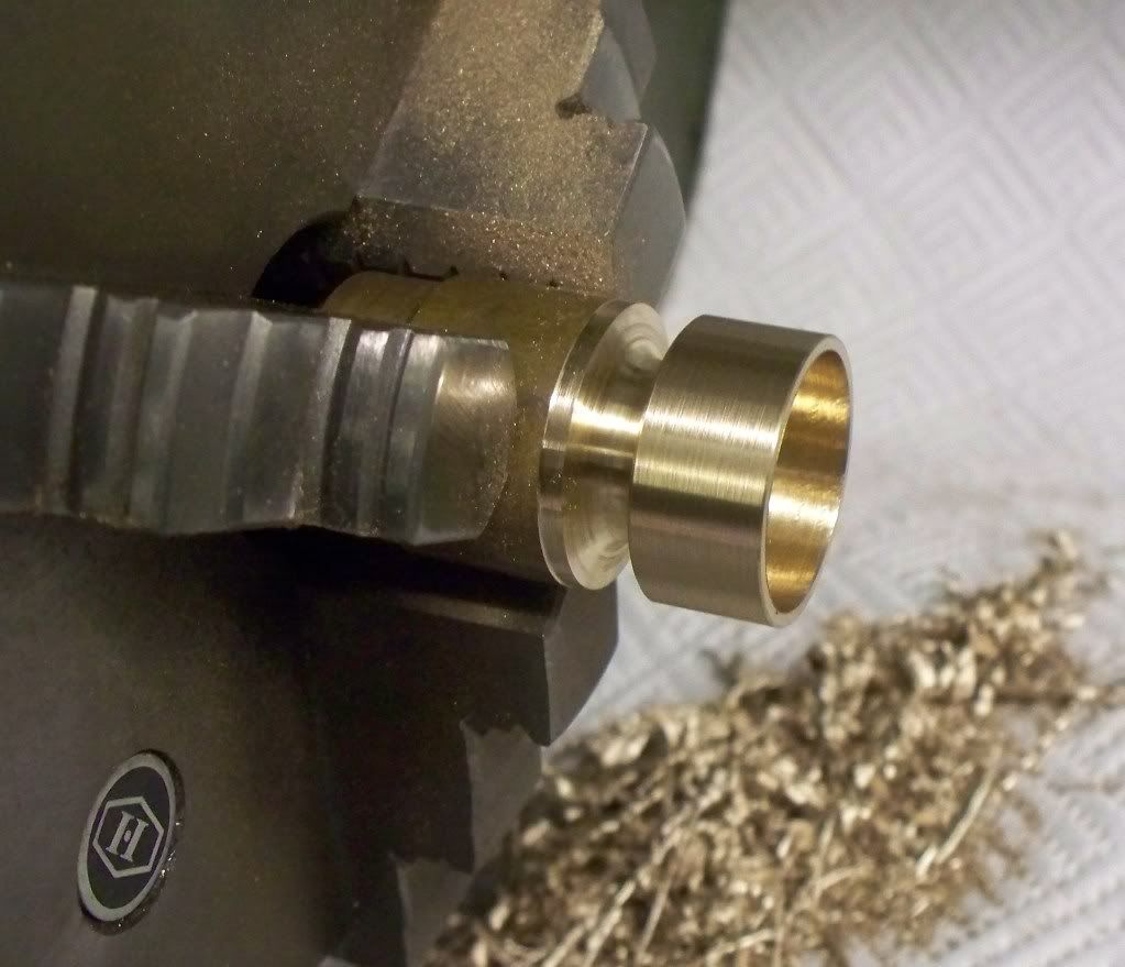
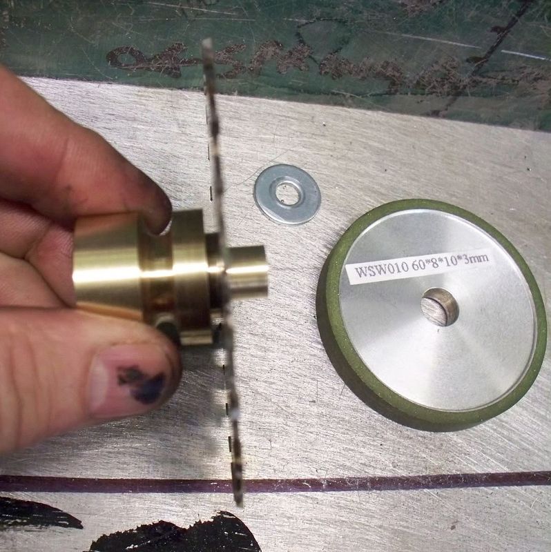
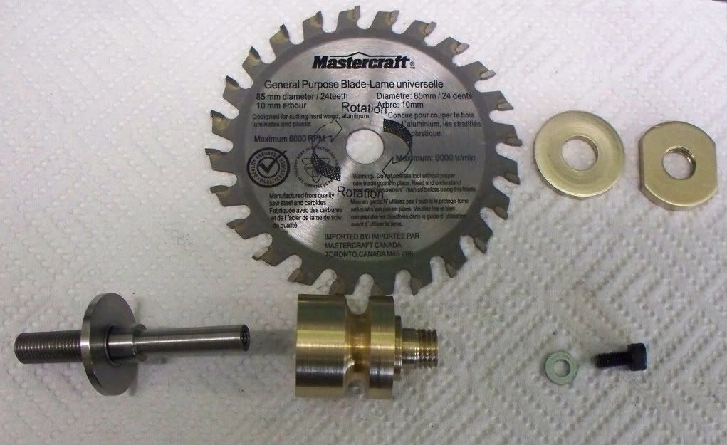
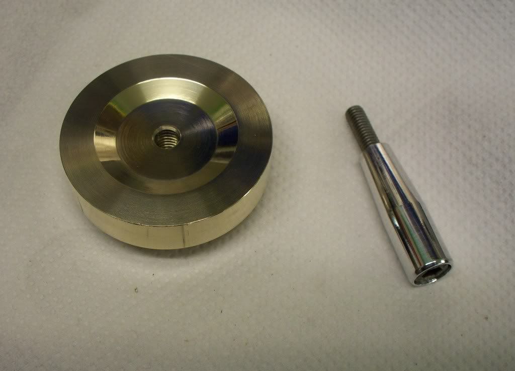
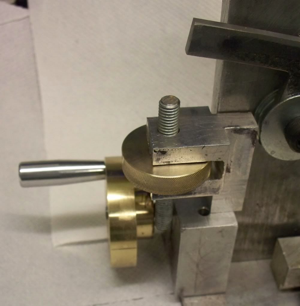
Leaving design for a moment I made a start on the main pulley that will hold either the larger saw blade on one section or the smaller blade or the diamond grind wheel on another, since they have the same bore. The front of this pulley will have two diameters for the blades/wheel and the rear of the pulley will contain a sealed bearing.
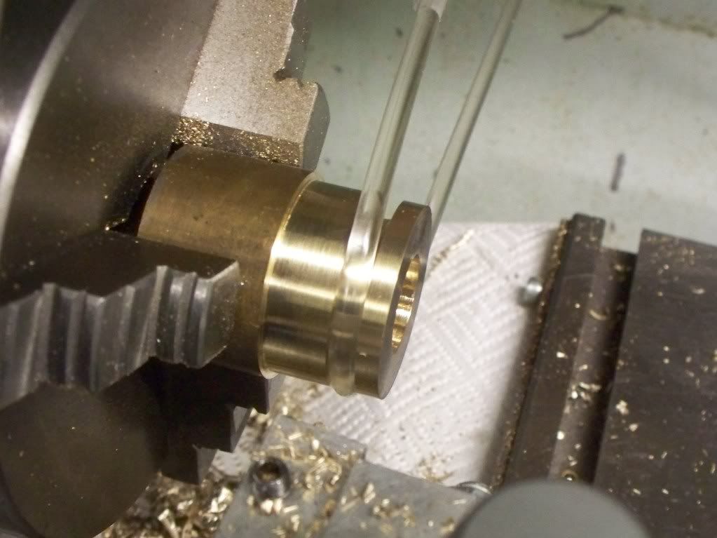
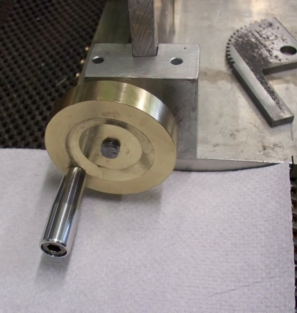
So far the pulley has been turned to outside diameter and the belt groove done (photo). The bore has been drilled and reamed with a start made on the bearing housing but was put to one side whilst the bearings were ordered (arrived in just two days!). Hence a start being made on the saw arm using a ¼ (0.250 or 6.35mm) thick piece of flat steel.
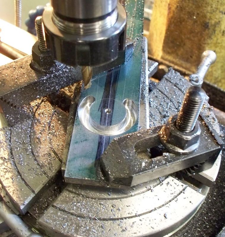
I am happy using the DROs to co-ordinate the machining of parts but I still like to mark out the design to make sure I am in the right place as it were. So after marking out the arm, the rotary table was secured to the milling table and a start made in cutting the small end of the arm (photo). When it came to the larger end I had to make new clamps so the complete part of the diameter could be milled and that is where the project was left at the end of the latest session.
Tomorrow I hope to complete the arm profile and maybe the inserts and perhaps the saw head pulley. I dont expect to spend too much time on the basic saw table, before switching to the Fowler Traction engine before going back to the pair of Seal 4 cylinder petrol engines.
I have finally decided that these are the three main projects I will concentrate on over the next couple of months and try to keep other engineering distractions at bay. Again, time will tell ..
Carbide tipped saws have been recommended for metal work in the past, especially when they are slitting saw size. In the UK I couldnt find a supplier of small blades but a HMEM forum member (from Canada) sent me some blades to try. There are some really nice people in the model engineering fraternity. I am sending a traction engine book back to Canada (as soon as it comes back into Amazon stock!) but thanks are in order.
Instead of just trying the blade in my slitting saw arbor I thought I would bring forward an idea I had about building a saw table. The reason I wanted to trial the carbide tipped saws was to cut a round bar in half so I can make two crankshafts for the Seal build. Since the camshafts have now been made the next major item for the Seals is the crankshafts, so you can see all roads in fact led to the saw table.
Since I dont sleep very well I often ponder designs during the night, scribbling down some drawings at my 0600ish breakfasts. I started by writing out the design criteria at one of these breakfasts, with the aim of making some CAD drawings, leading to a set of plans (Alibre) which could be made available on my website. So this particular project covers many areas of interest for me. Such as making a workshop tool, using CAD, and helping with the Seal twin engine project. Not a bad result really.
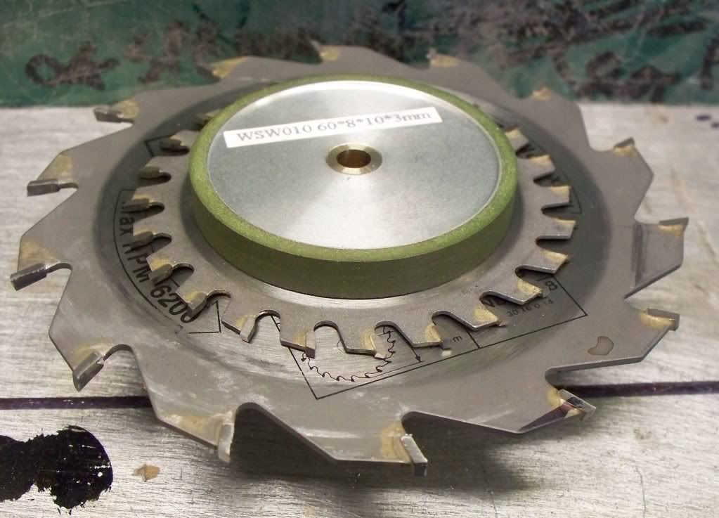
The design criteria covered such things as having two blade sizes (please see photos) so it would be useful to be able to use both blades on the same machine. The blade depth of cut should be adjustable and by a measured amount. The top should be as adaptable as possible, allowing the safe holding of materials. The blades should have some form of safety guard and make use of an existing electric motor I have.
Other ideas will no doubt come up as I progress, especially in the area of the work holding. I dont feel confident enough yet to just draw the design out in 3D CAD. Rather it will be a bit of both, build and the use of Alibre CAD. The help in laying out the plan I used some foam rubber/plastic as a former to check the size of the saw arm and the quadrant. By using these materials in a mock up I discovered my initial quadrant lever would not work so a new shape was soon cut out and tried.
Since I have several ¼ (0.250 or 6.35mm) sheets of aluminum recovered from my local scrap yard I wanted to use these to make a strong box shaped saw table (please see photo).The first task was to check the speed of the electric motor. I have a rev counter which measures revolutions from model aero engines and made up a temporary shaft to hold the Mills propeller. The measured speed was approximately 1200 rpm. The saw blades run at around a maximum 6000 rpm so I needed to increase the speed from the motor.
I had a look at the spare gears from the Myford and there were both 20 tooth and 65 tooth gears that can be used. That should give me around 4,000 to 5,000 rpm at the blade. With these speeds I decided that all pulleys will have bearings and it was whilst searching for bearings I saw a diamond grinding wheel that would also fit the design. So I ordered the bearings and the diamond cutting wheel.
Now the project has turned into a versatile saw and grinding table which longer term I would also like to develop to grind camshafts in the future. Madness you may say (and you may well be right!) but if you take the saw table top as a base for holding various fixtures, then it should be an ongoing (maybe years) development for my own tool centre.
The rough design schematic is shown in the photo below to help you understand where I am going. To make the blade/grinding wheel adjustable I will use a quadrant with teeth cut into it, matching with teeth on the saw/grinding wheel arm. With the screw thread used for adjustments I should be able to make fine and measured cuts. Since this movement involves the arm then the pulleys will need to have a tensioning system to take up the difference.
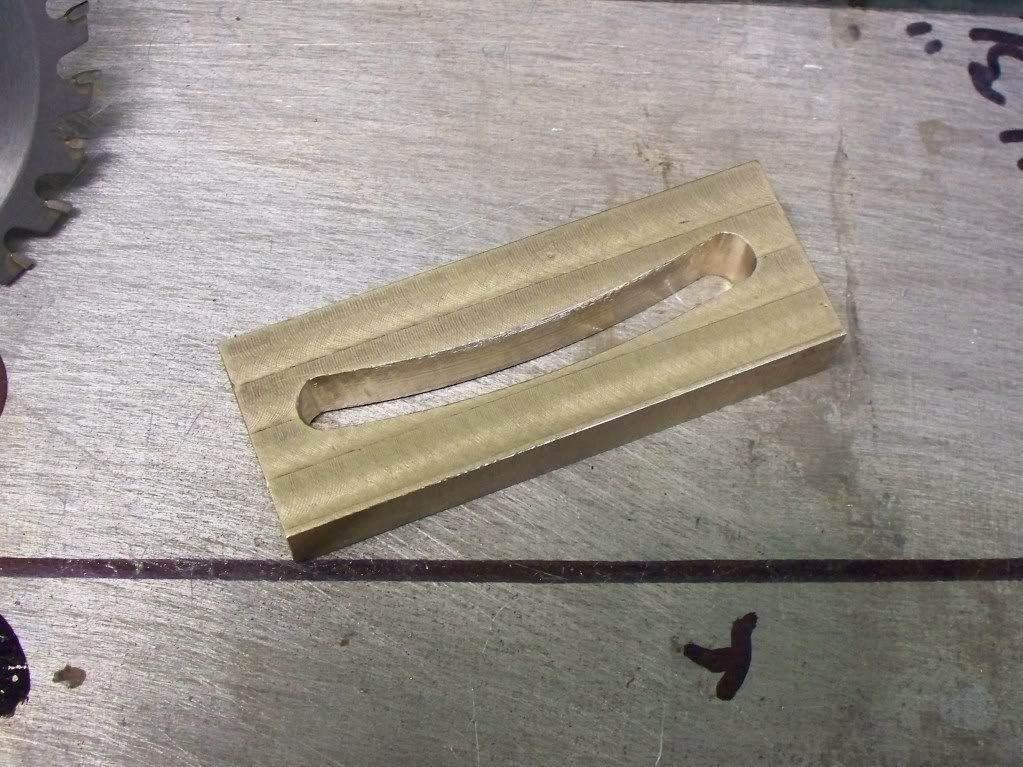
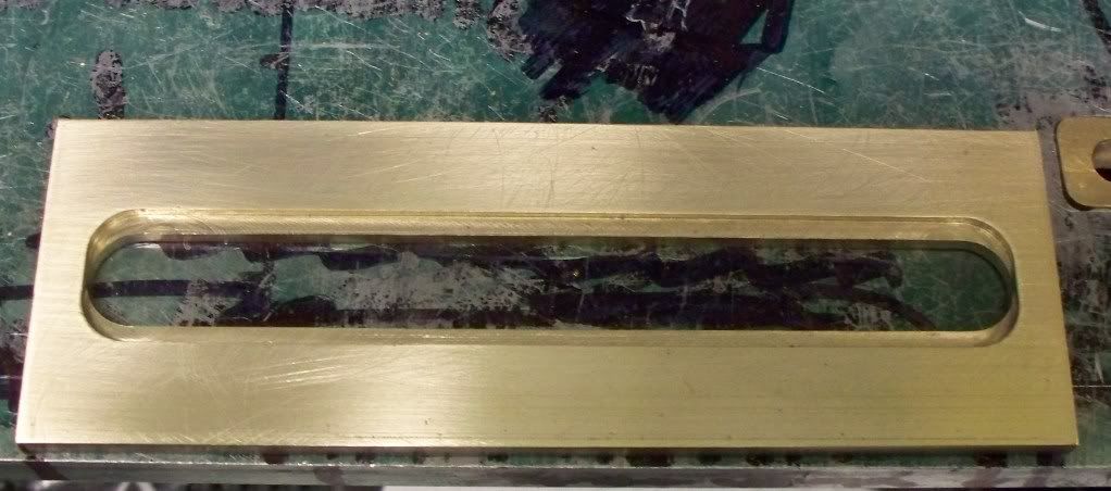
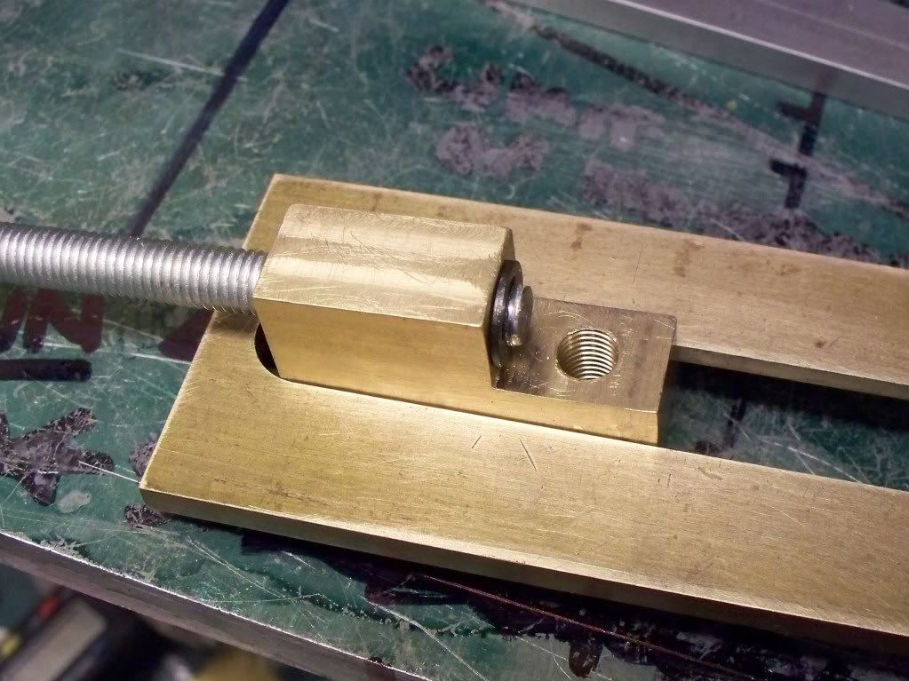
Since I hope to have the tool for many years I will also be looking at the materials used, for example the saw arm needs to have a guide and clamp to secure it when any adjustment has been made. Just cutting through the aluminum wouldnt really serve long term so I am letting into the plate a brass section (made from two lengths of square bar silver soldered together).
The drive belt I shall be using is circular in cross section and the two ends are welded together (see photo), access to the belt as well as the gears (in case I need them on the Myford) and saw/grinding wheel needs be incorporated for change of belt, blades or now the additional grinding wheel.
Leaving design for a moment I made a start on the main pulley that will hold either the larger saw blade on one section or the smaller blade or the diamond grind wheel on another, since they have the same bore. The front of this pulley will have two diameters for the blades/wheel and the rear of the pulley will contain a sealed bearing.
So far the pulley has been turned to outside diameter and the belt groove done (photo). The bore has been drilled and reamed with a start made on the bearing housing but was put to one side whilst the bearings were ordered (arrived in just two days!). Hence a start being made on the saw arm using a ¼ (0.250 or 6.35mm) thick piece of flat steel.
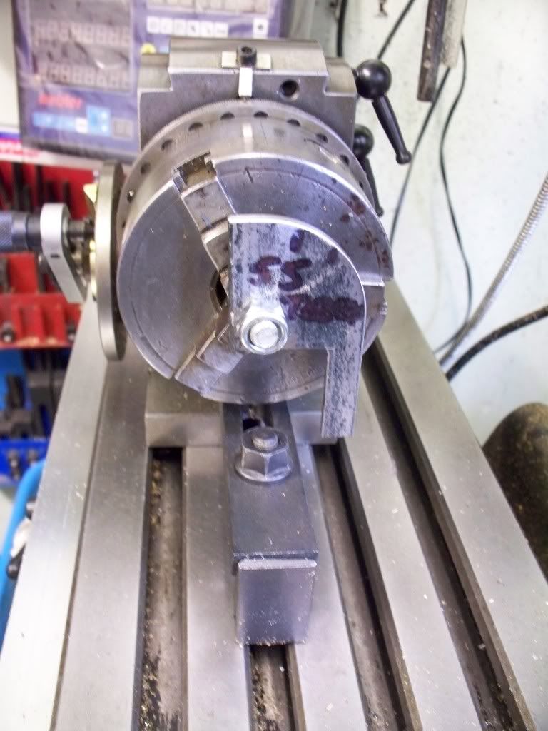
I am happy using the DROs to co-ordinate the machining of parts but I still like to mark out the design to make sure I am in the right place as it were. So after marking out the arm, the rotary table was secured to the milling table and a start made in cutting the small end of the arm (photo). When it came to the larger end I had to make new clamps so the complete part of the diameter could be milled and that is where the project was left at the end of the latest session.
Tomorrow I hope to complete the arm profile and maybe the inserts and perhaps the saw head pulley. I dont expect to spend too much time on the basic saw table, before switching to the Fowler Traction engine before going back to the pair of Seal 4 cylinder petrol engines.
I have finally decided that these are the three main projects I will concentrate on over the next couple of months and try to keep other engineering distractions at bay. Again, time will tell ..