G’day All,
Going back a few years a mate of mine (Len) decided to design and build a scale model stationary engine loosely based on one of the full size engines in his collection. He made all of his own patterns and even had a crack at doing the casting himself before deciding to get this done at a foundry. The story of how he designed and built The Billabong Engine (as it’s named) can be found on his website and is worth a read if you get a chance: http://members.iinet.net.au/~hoppi/MakingABillabongEngine.html
In January 2014 he was getting some castings done for a steam engine and asked me if I would like to get a set Billabong engine castings done at the same time and of course I jumped at the chance. After picking the castings up from the foundry they sat in a box for a few months and it was not until April 2014 that I started to do some work on them. This will be my first model engine build and is going to be a long term project. Given that I started on this a year ago now these first few posts will cover the work done since then and may give the false appearance of rapid progress. Unfortunately this is an illusion and progress has been slow however I endeavour to keep working away on it and will post updates as things progress.
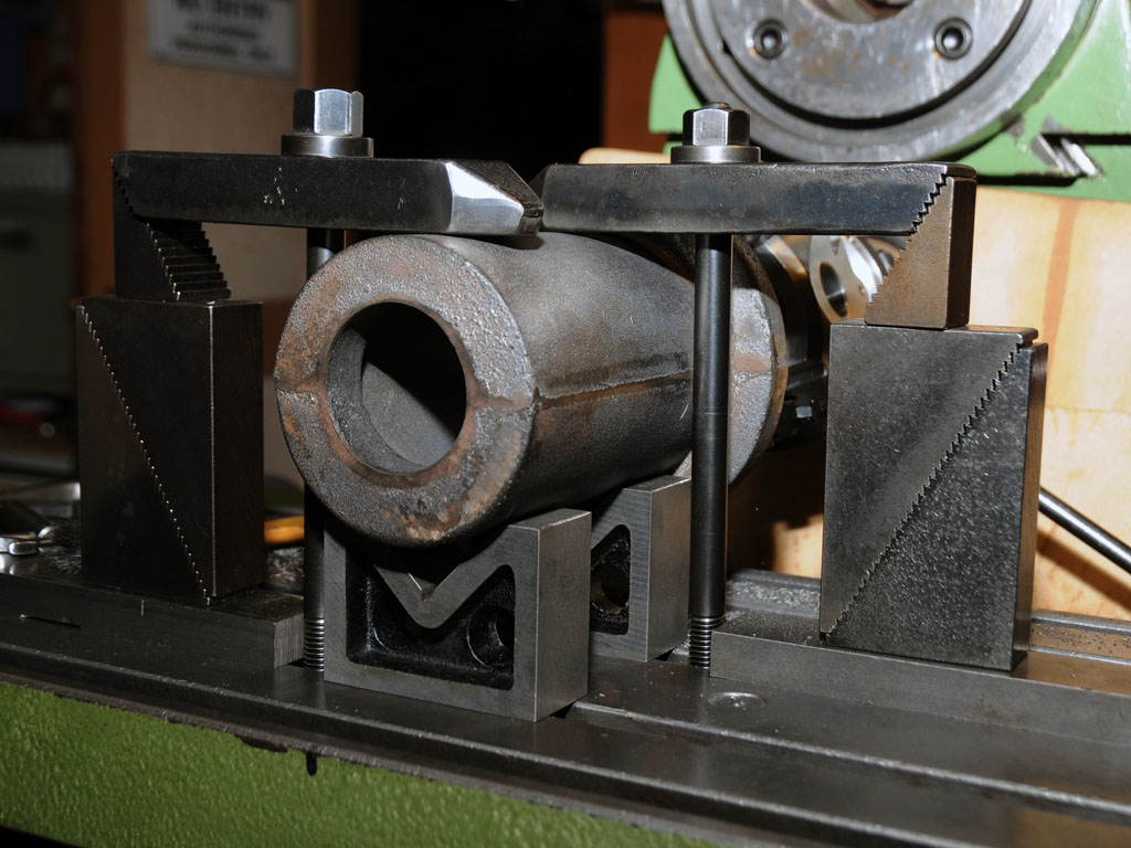
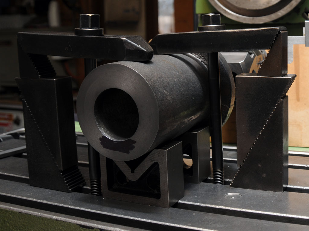
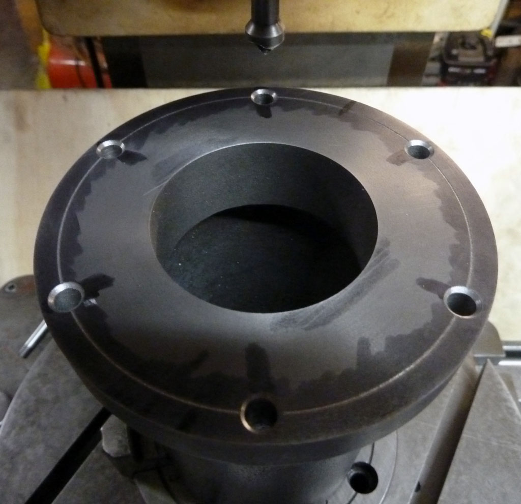
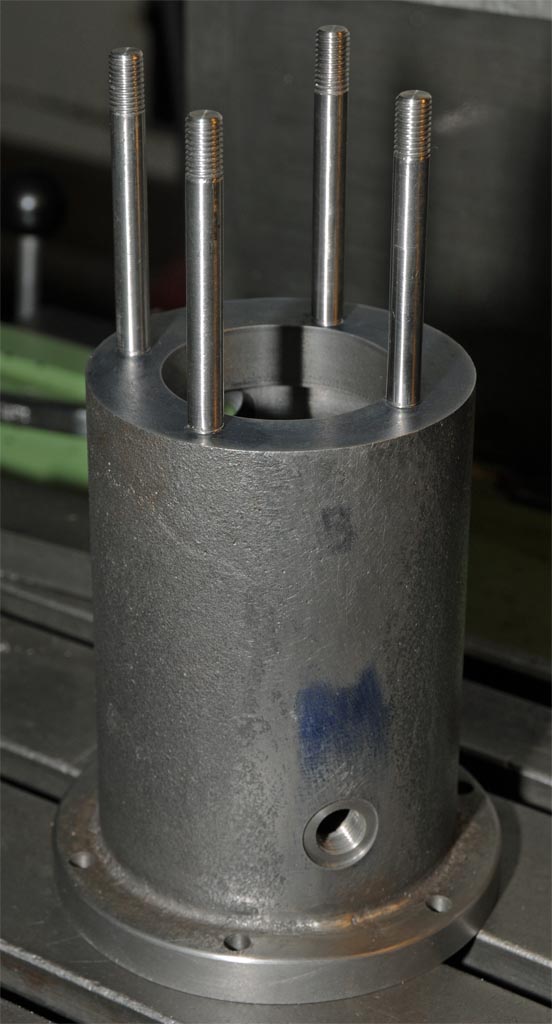
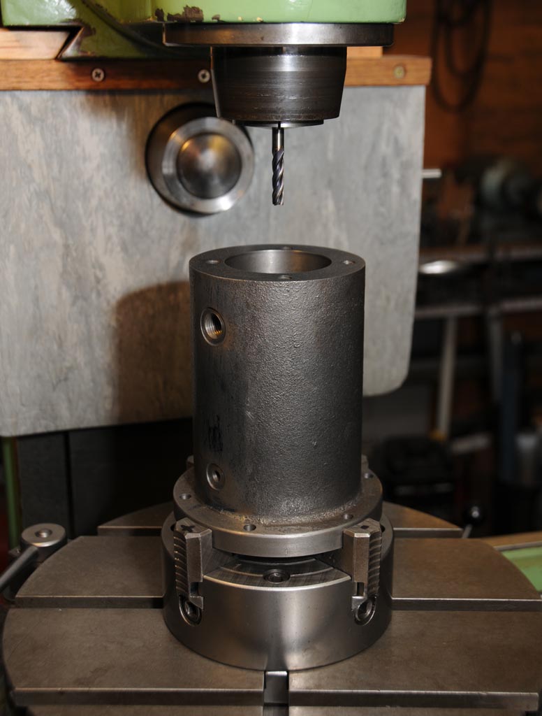
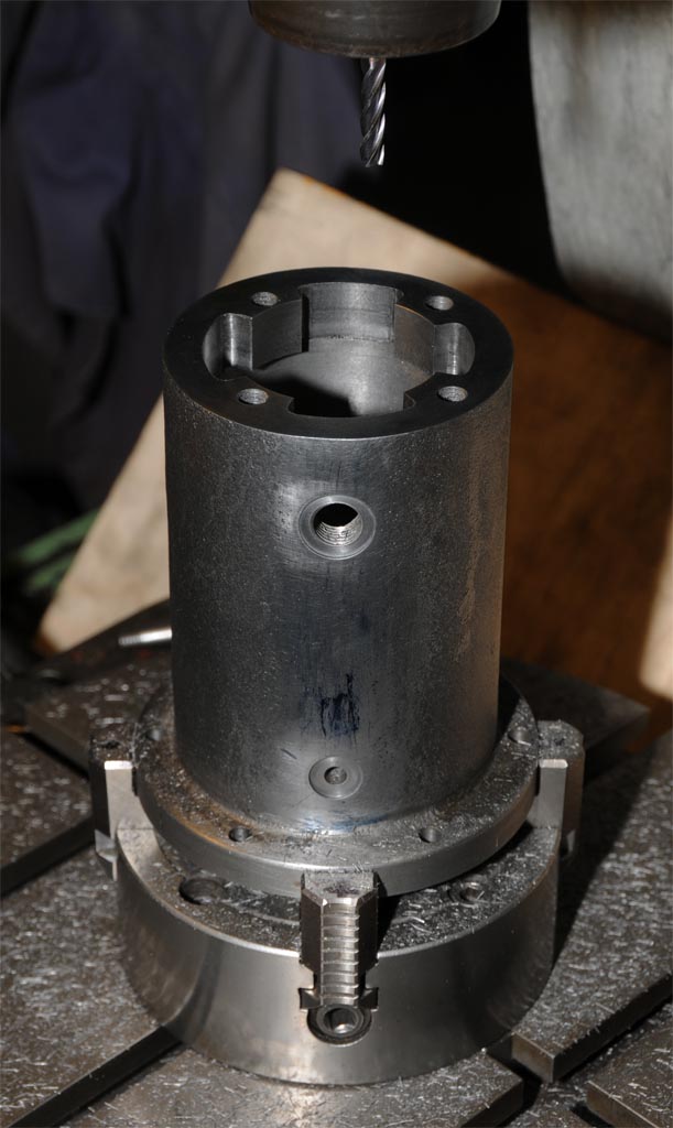
First job was to machine the bottom of the crankcase casting which will become the reference surface. The crankcase doesn’t have another surface parallel to its base so Len had made a fixture (which I borrowed) to support it so as to avoid messing around with jacks and packers. Just enough material was machined from the bottom of the casting to make an even surface which only required a couple of .020” passes to complete.
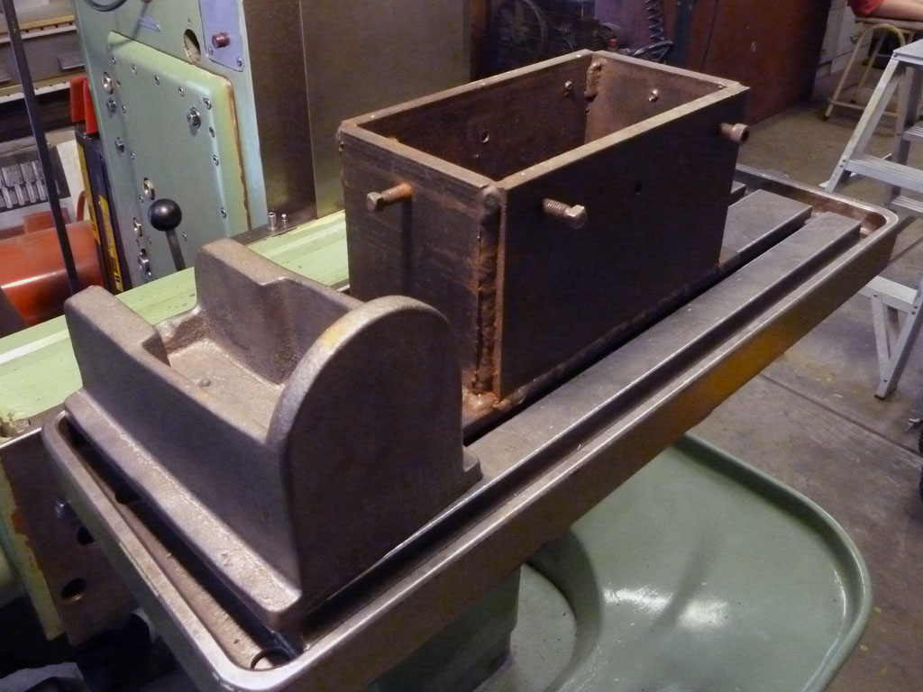
Base casting and support fixture.
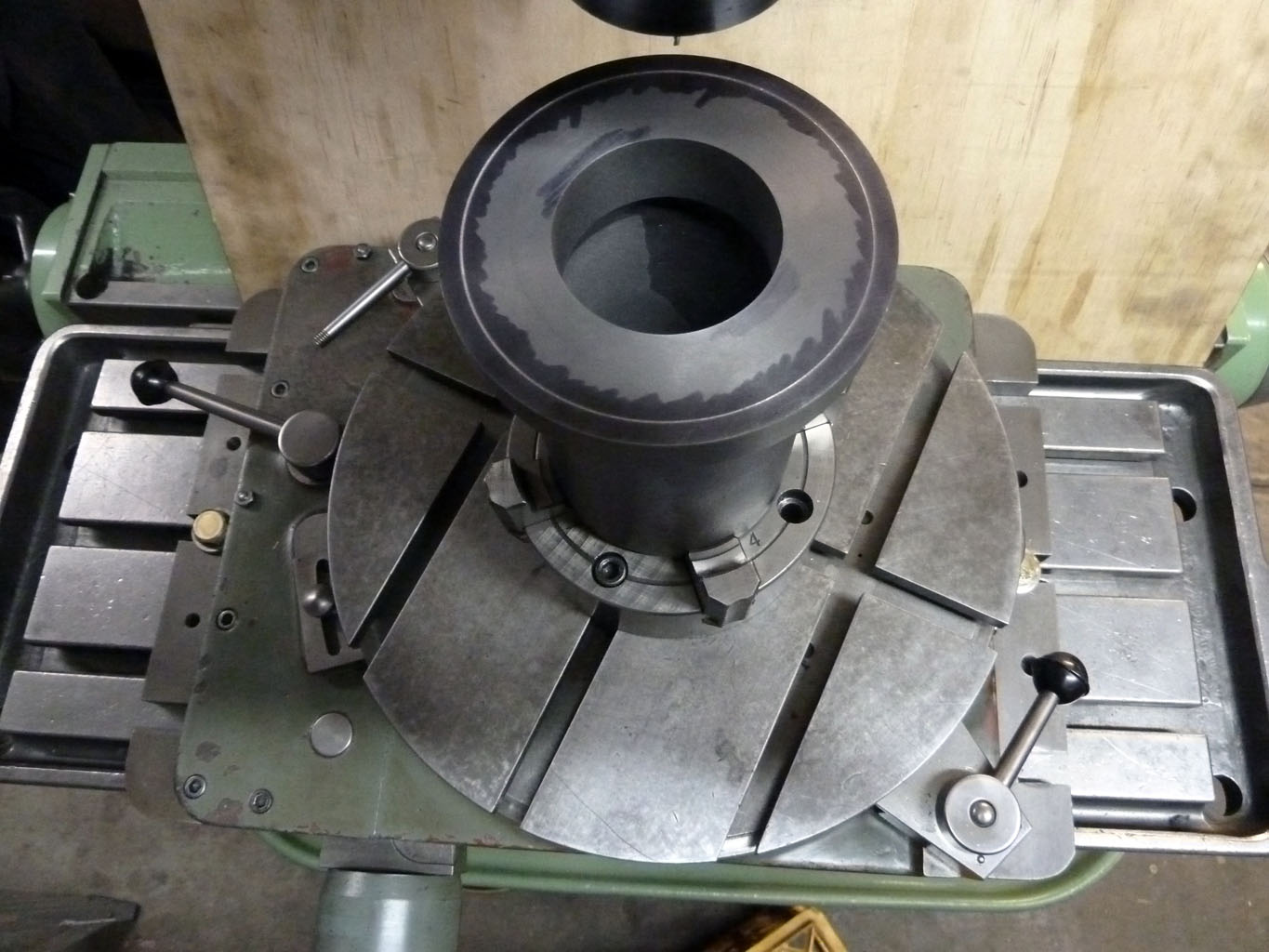
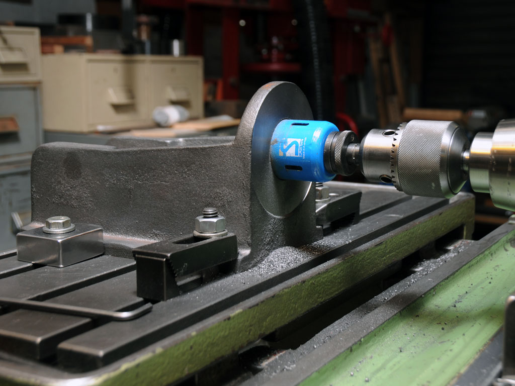
Machining the base.
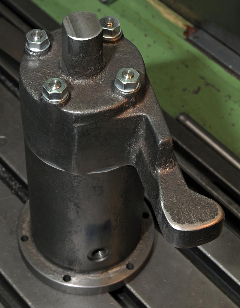
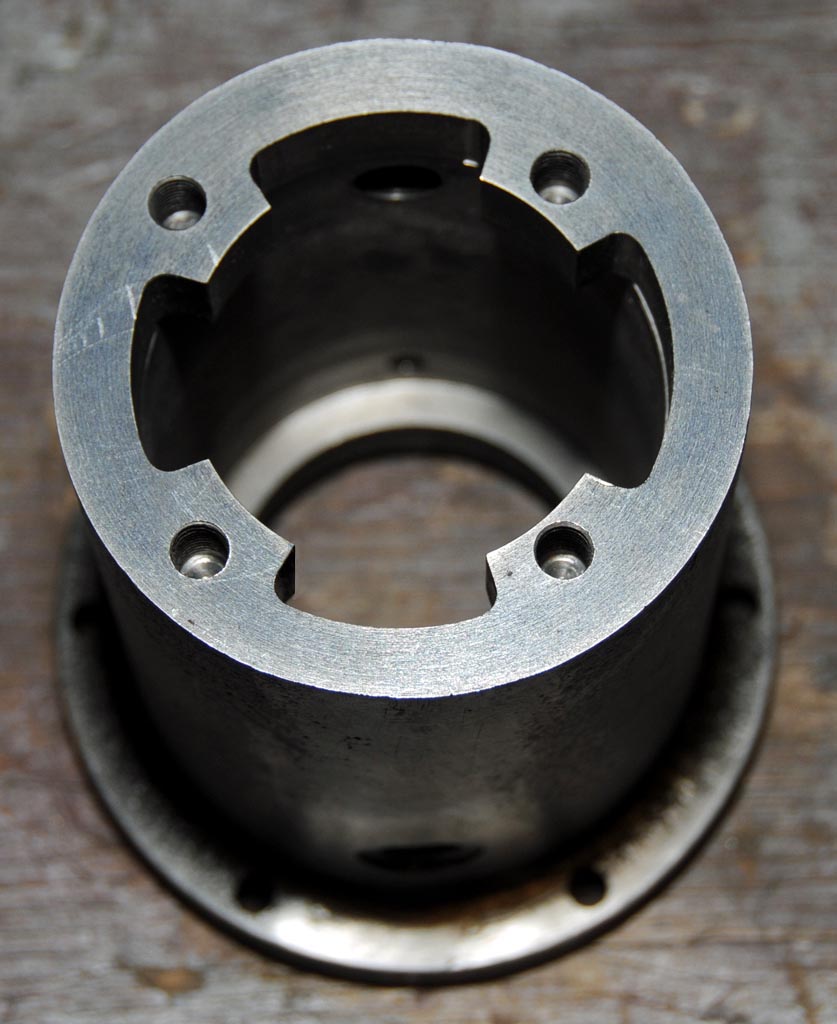
Job done.
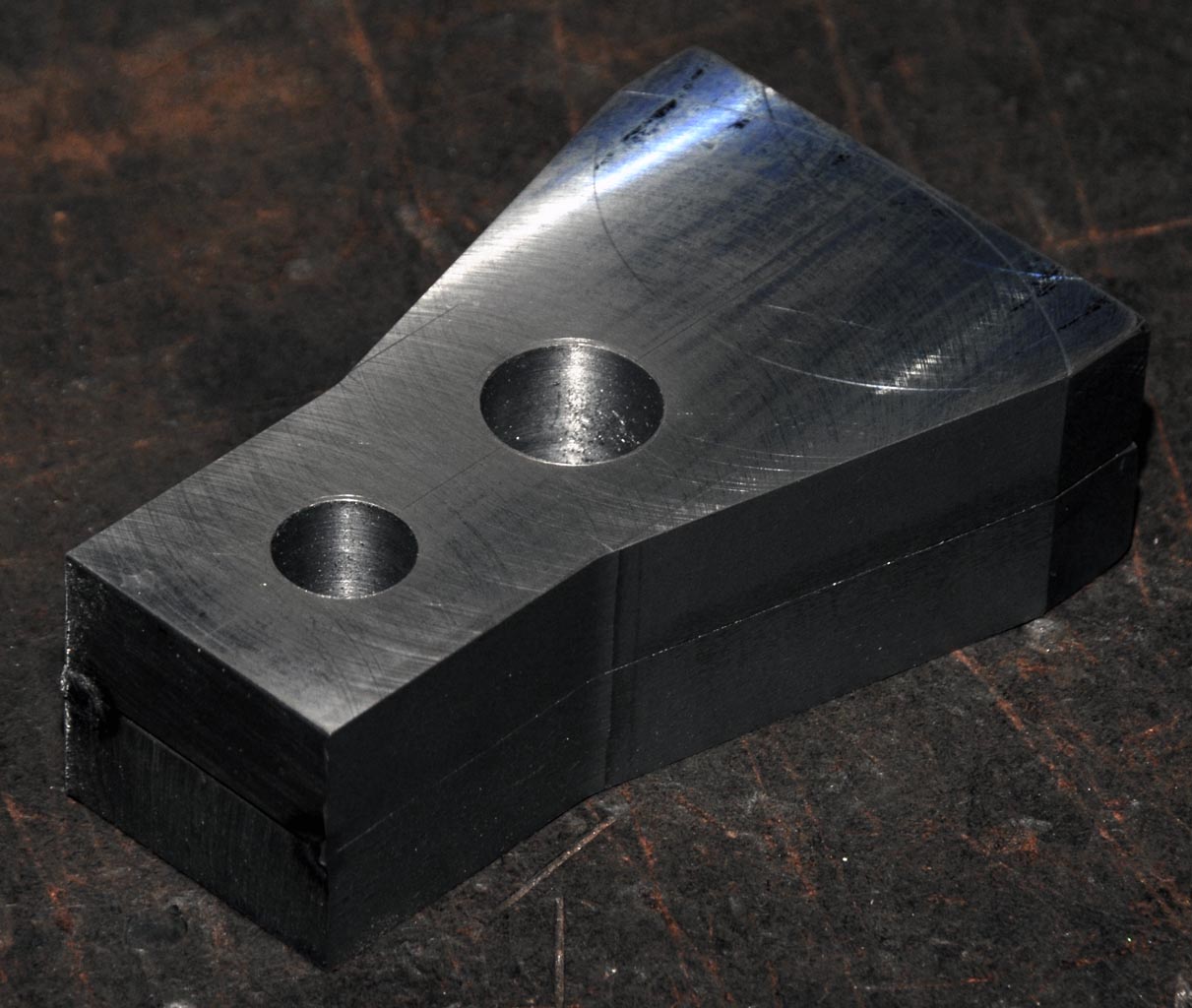
Main Bearing Caps
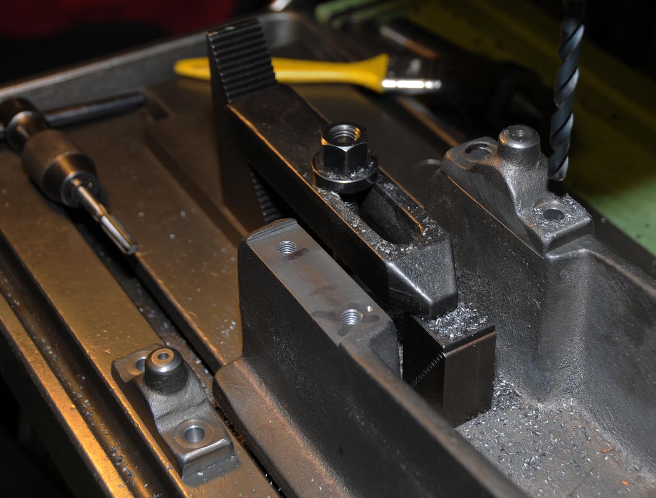
The main bearing caps needed to be finished to final dimensions so the seats in the base casting could be machined to a matching snug fit.
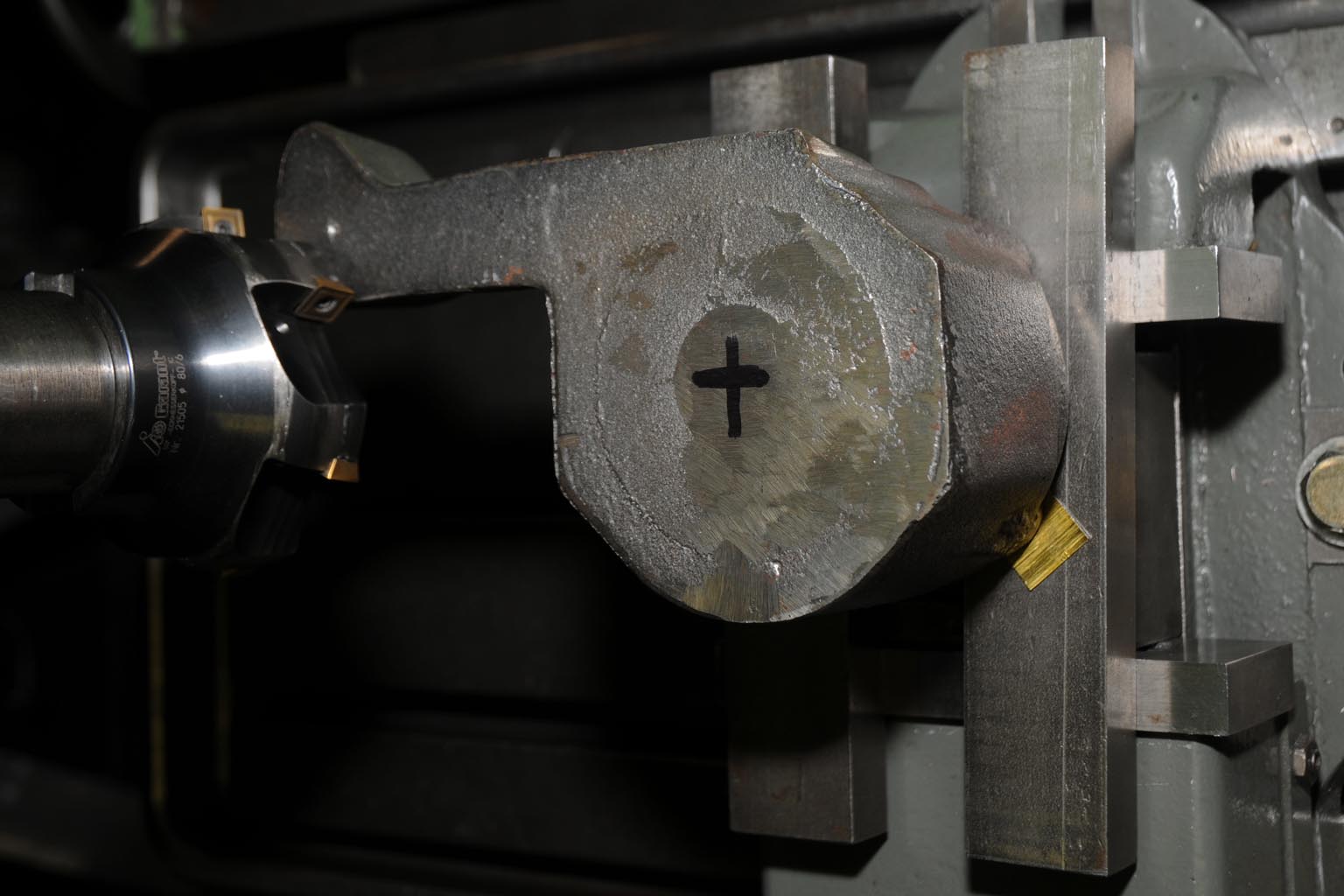
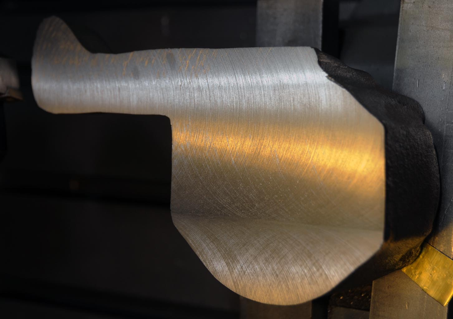
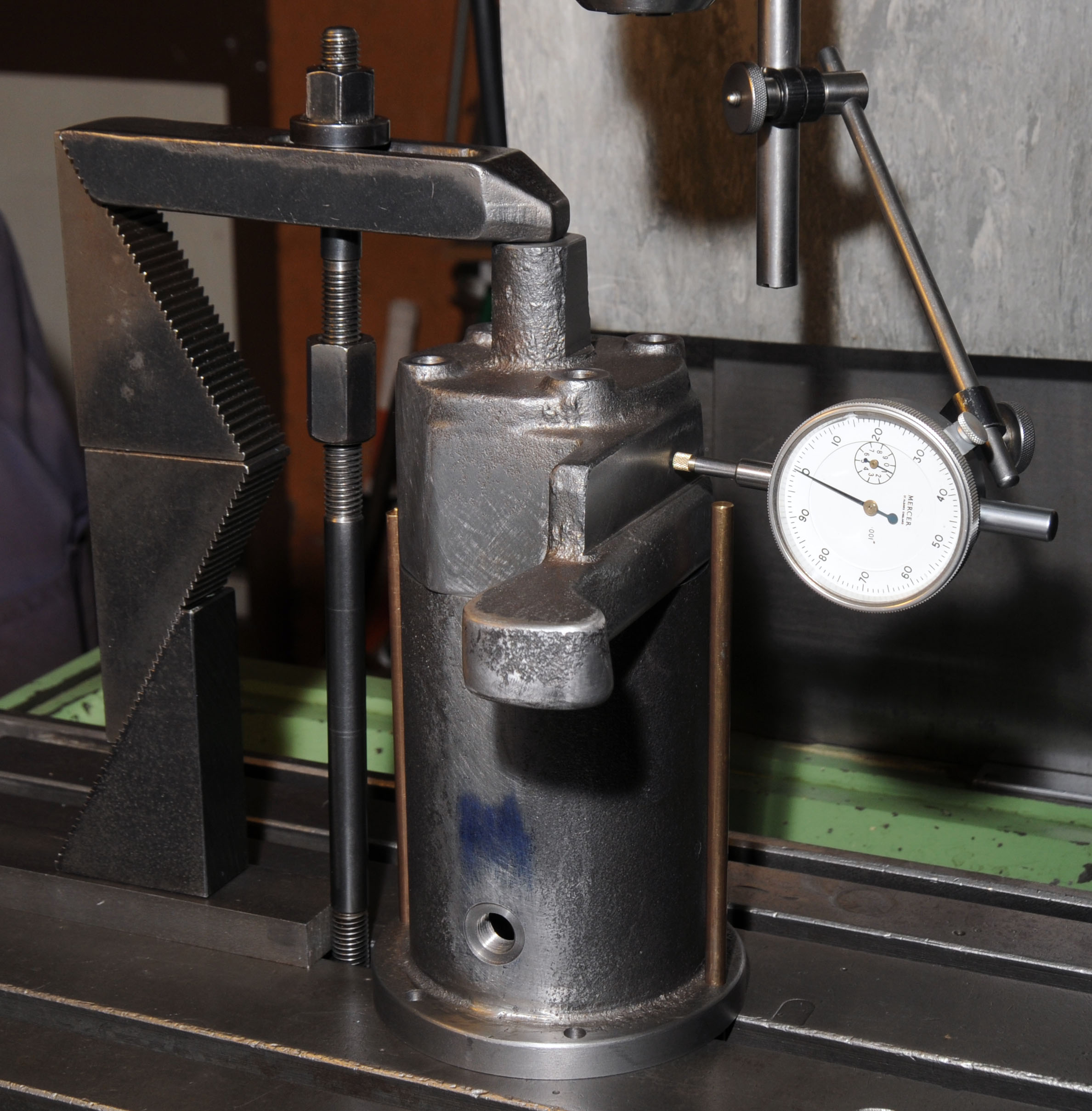
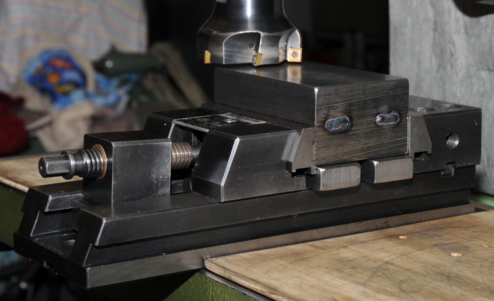
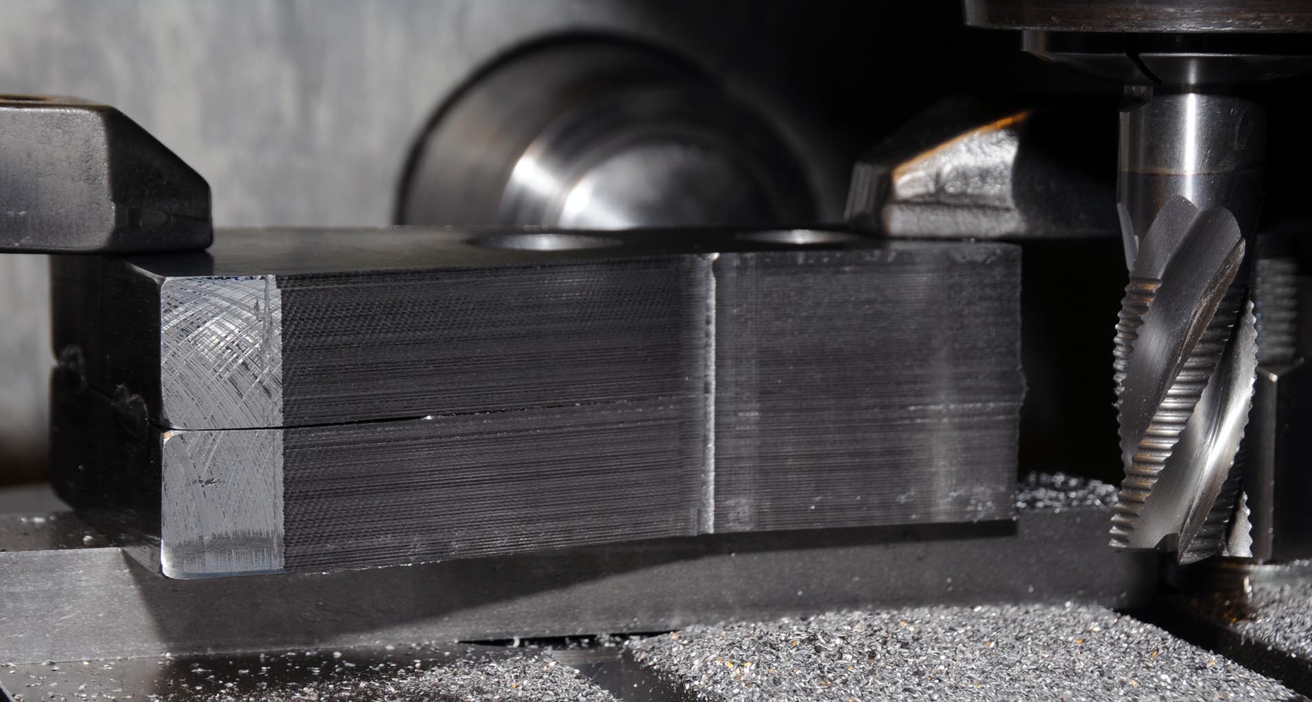
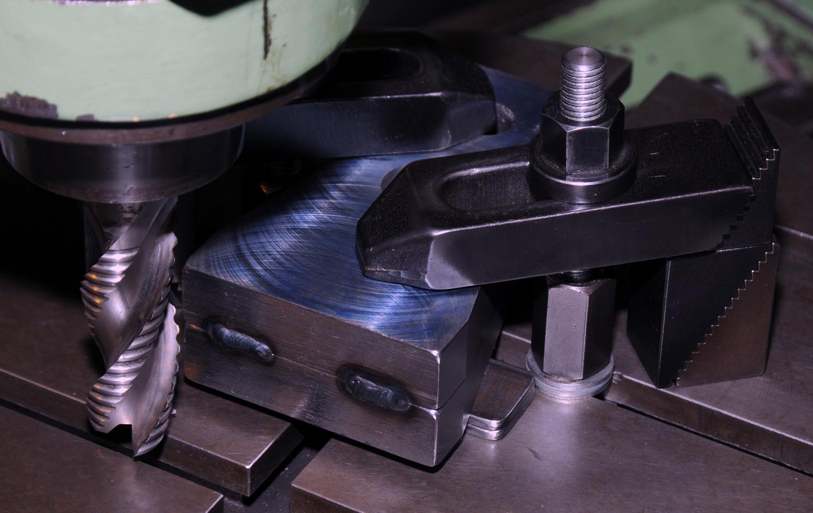
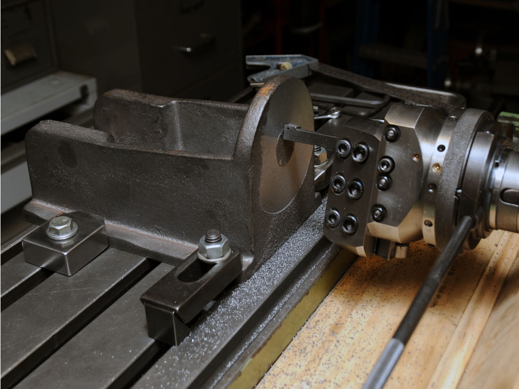
The first cap was clamped on its side in the vice and indicated in as even as possible before making a couple of clean up passes. The cap was then flipped over and positioned on a parallel so the other side could be machined flat and the width bought to a size that would fit neatly on the crank case. This process was then repeated for the second bearing cap.
I should probably mention at this point that there are no detailed plans or drawings for this engine, Len gave me a copy of his notes which includes hand sketches of the major components with indicative dimensions but nearly all of the machining needs to be done by the seat of your pants. This offers a lot of freedom but also means that careful thought needs to be given as to how work done on one component will affect its fit to another that may not yet have been machined. I have heaps of photos of a finished engine to refer to and will be able to discuss things with Len on the phone if necessary but the rest is pretty much up to my imagination
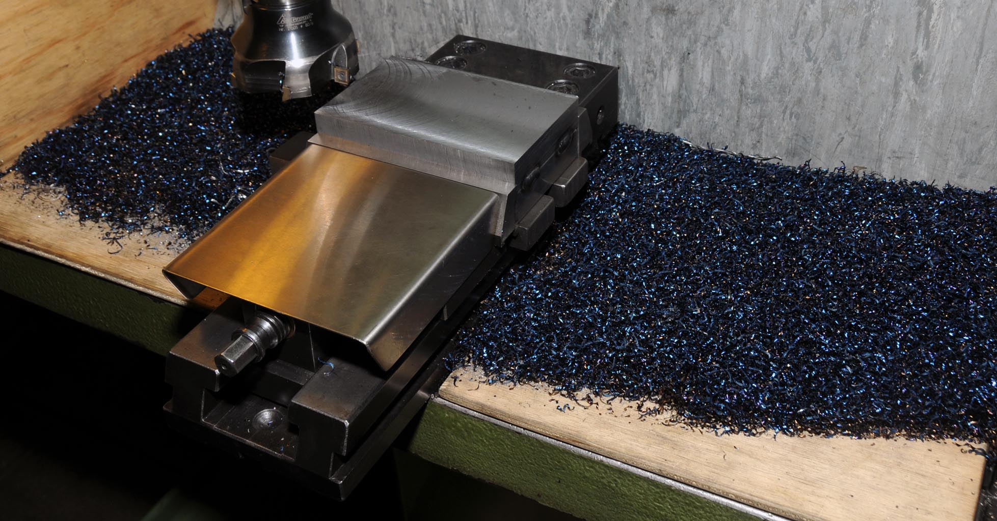
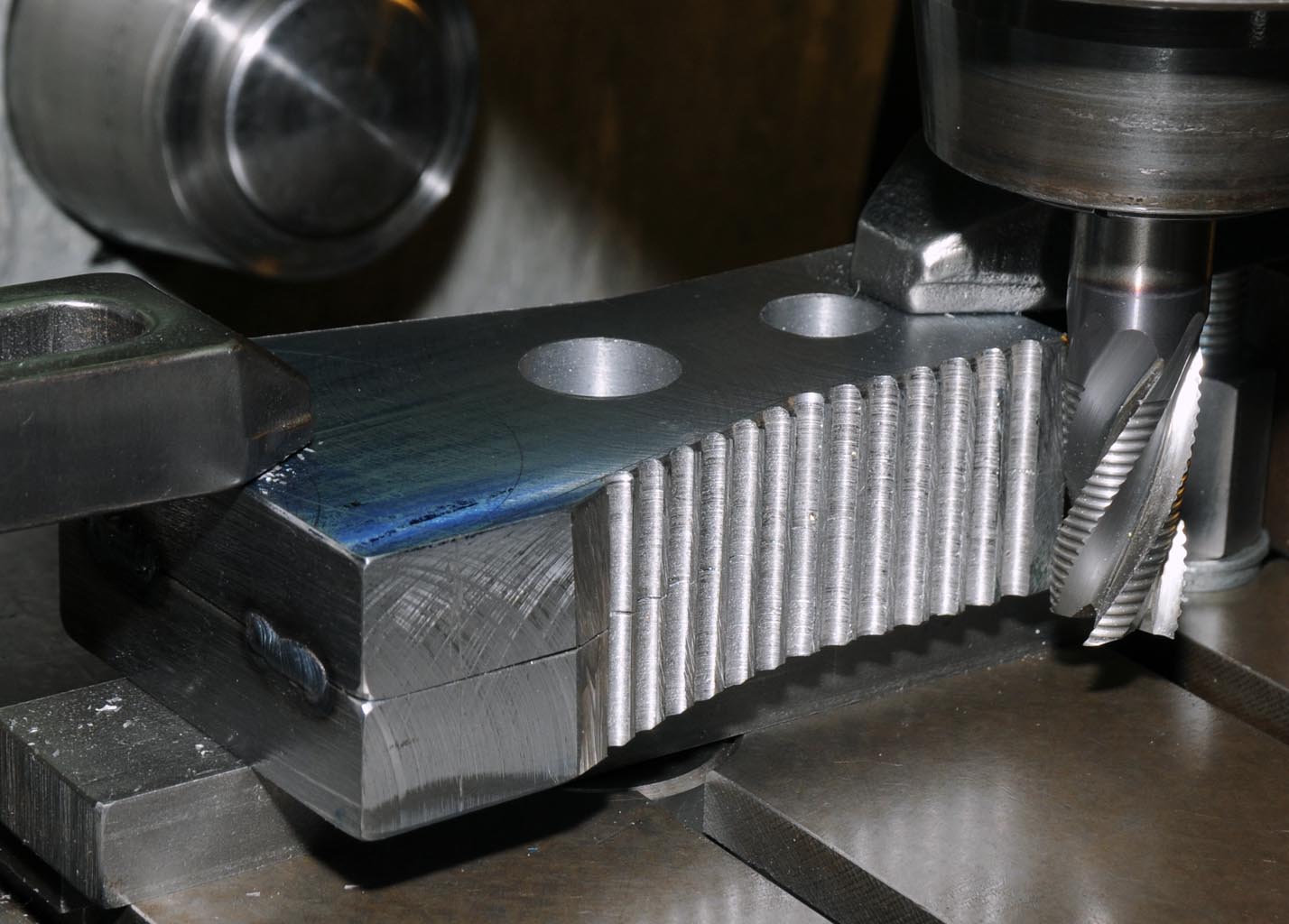
With the sides of both bearing caps now parallel they were clamped together in the vice so they could be machined to their final length of 2.625”. Both caps were then mounted together with the bottom facing up and the shoulders bridged across a couple of parallels and the bases machined to bring them to a height such that they would sit aesthetically on the crankcase while leaving enough meat to bore later on for the crank bearings.
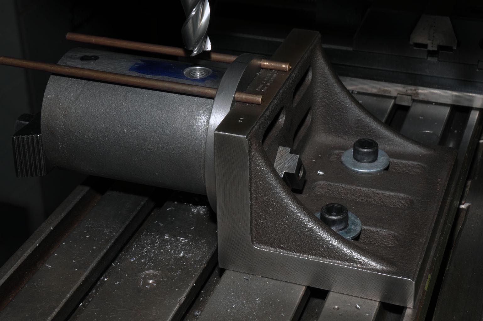
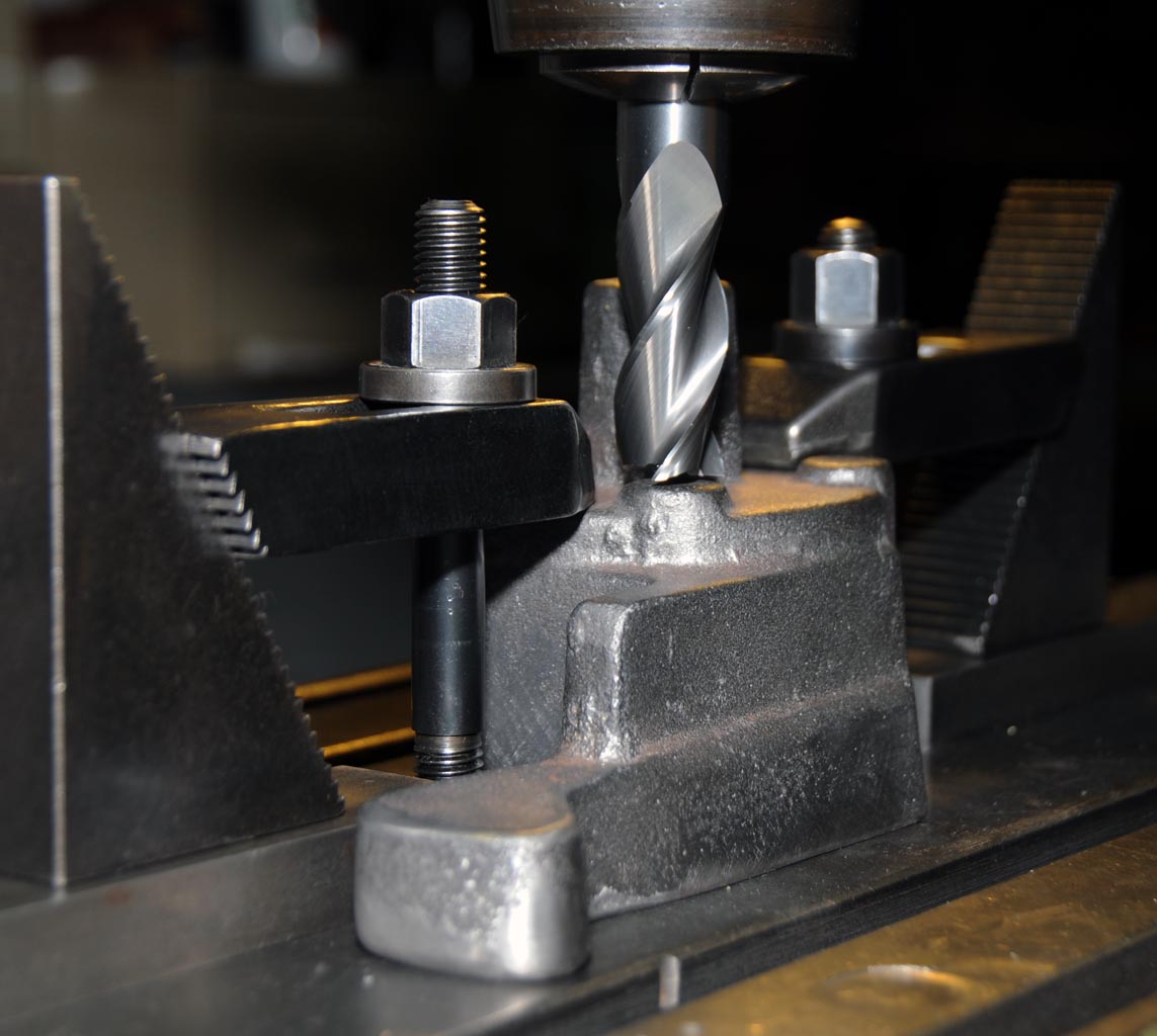
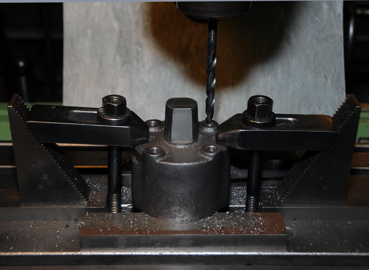
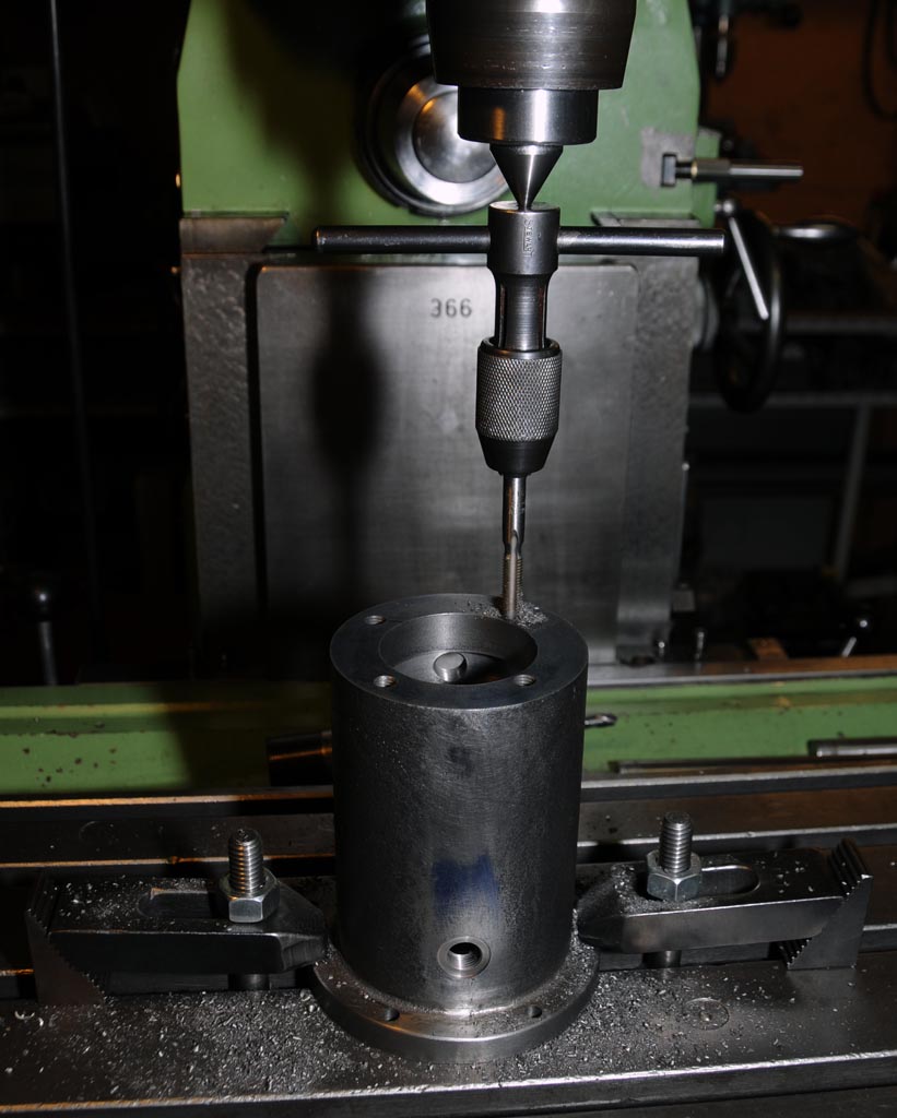
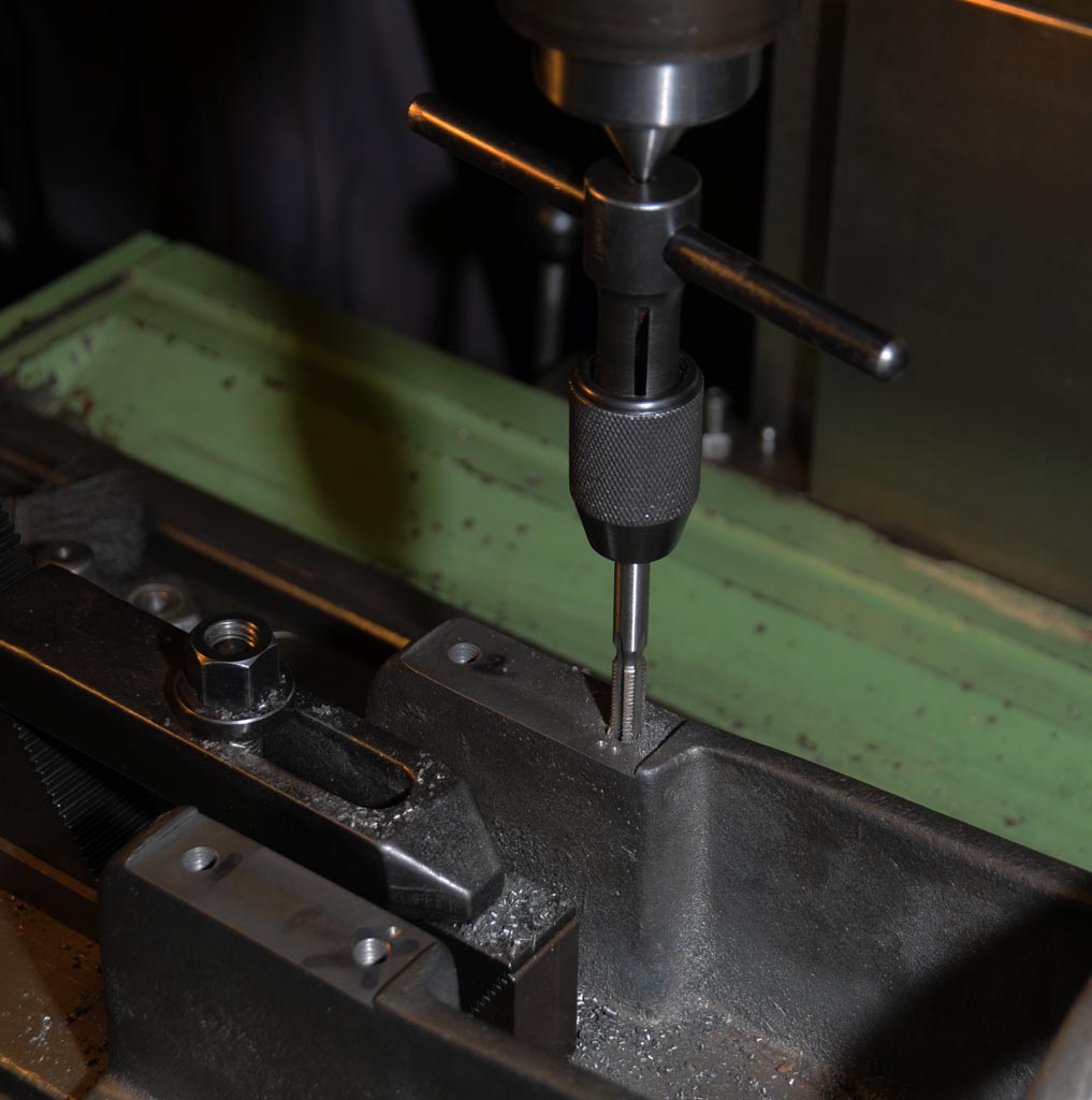
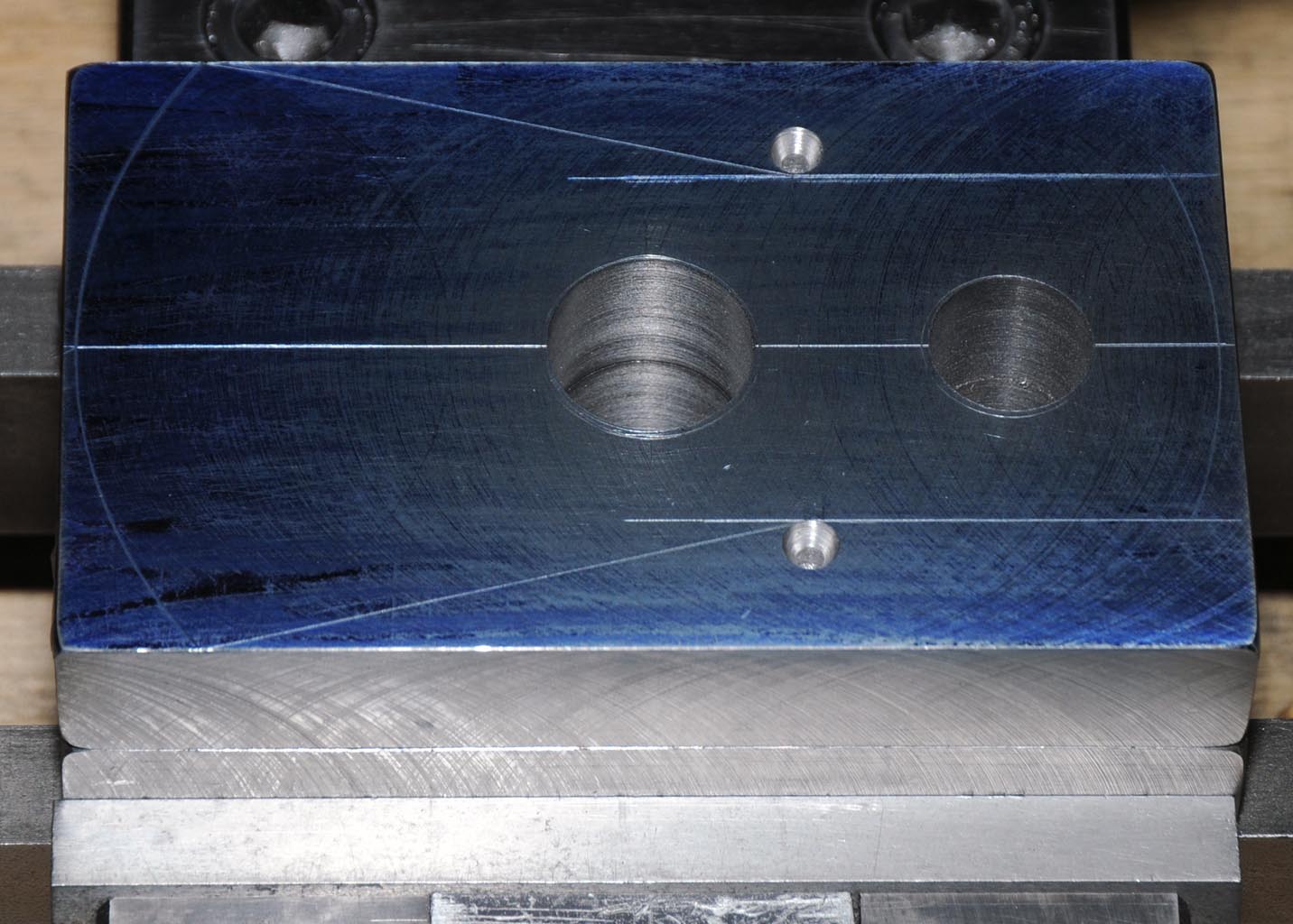
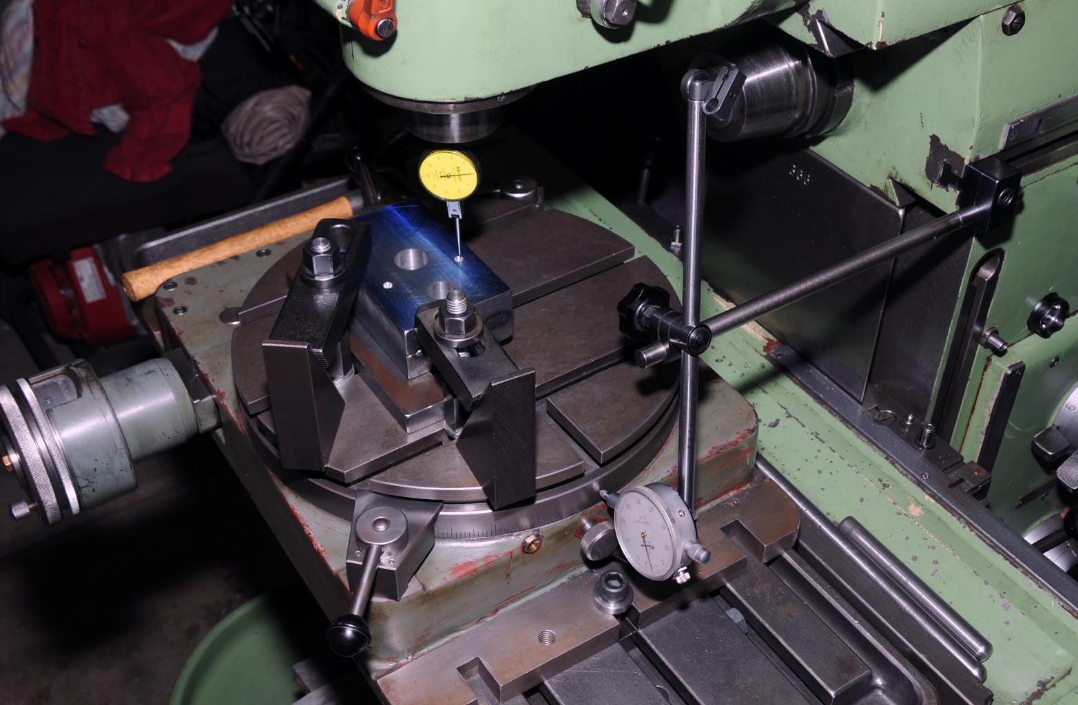
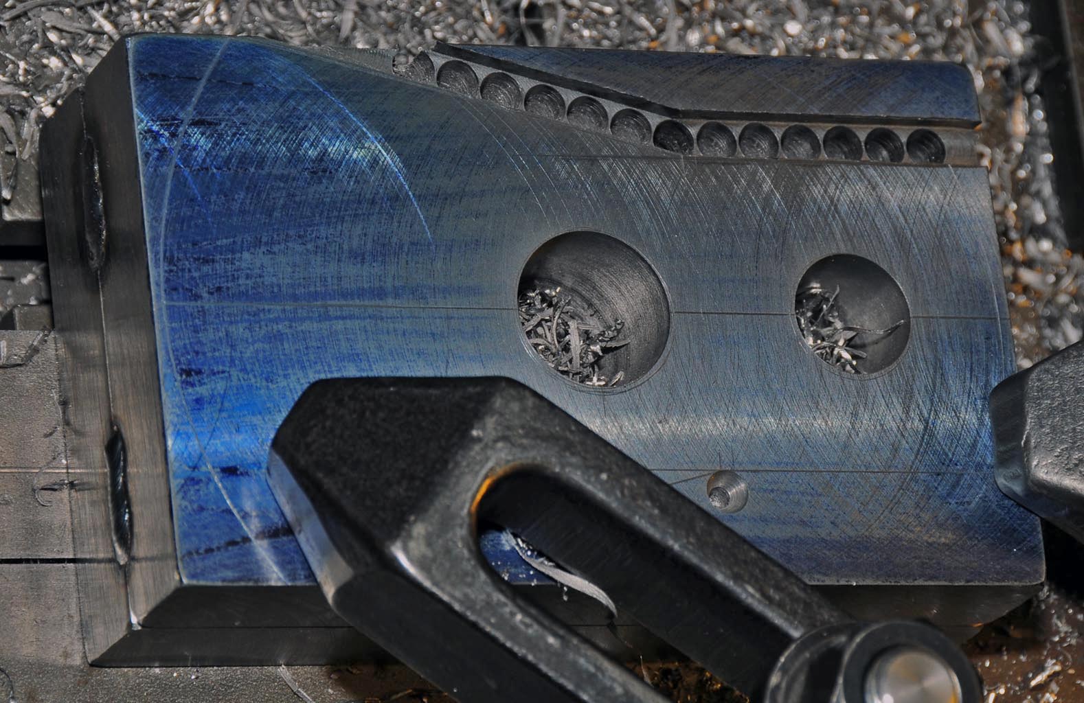
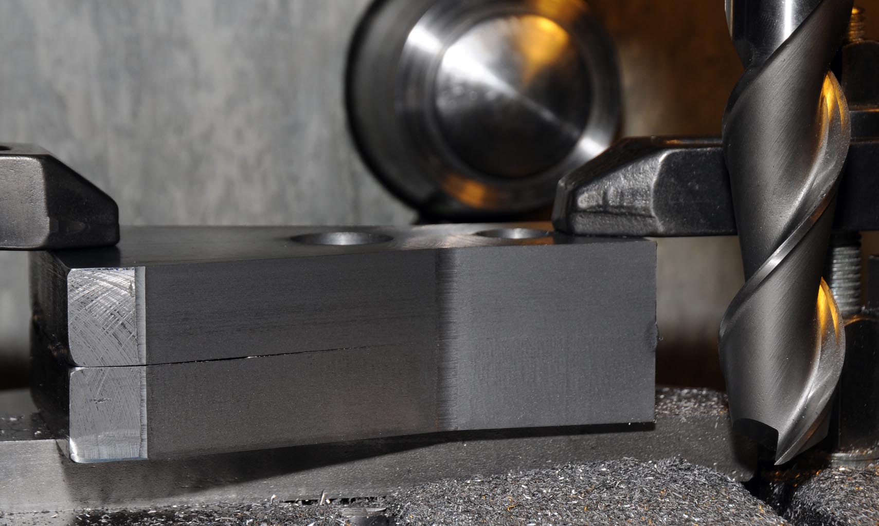
Finally they were flipped over and positioned on a parallel so the tops of the oiler bosses could be machined flat. The positions of the bolt and oiler holes were then marked out, spotted with a centre drilland pilot drilled to 4mm. The bearing cap castings don’t have bosses for the retaining bolts so each mounting hole was counter-bored with a 16mm slot drill just enough to allow the mounting bolts to sit flat.
Unfortunately I didn’t take any photos of this process and apologise if this is a bit wordy.
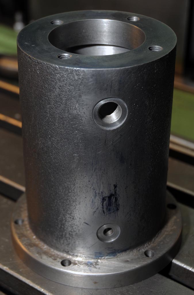
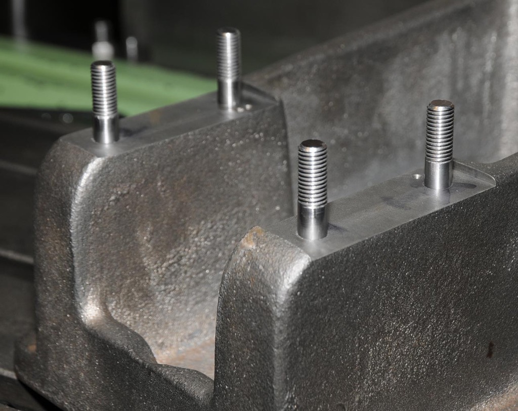
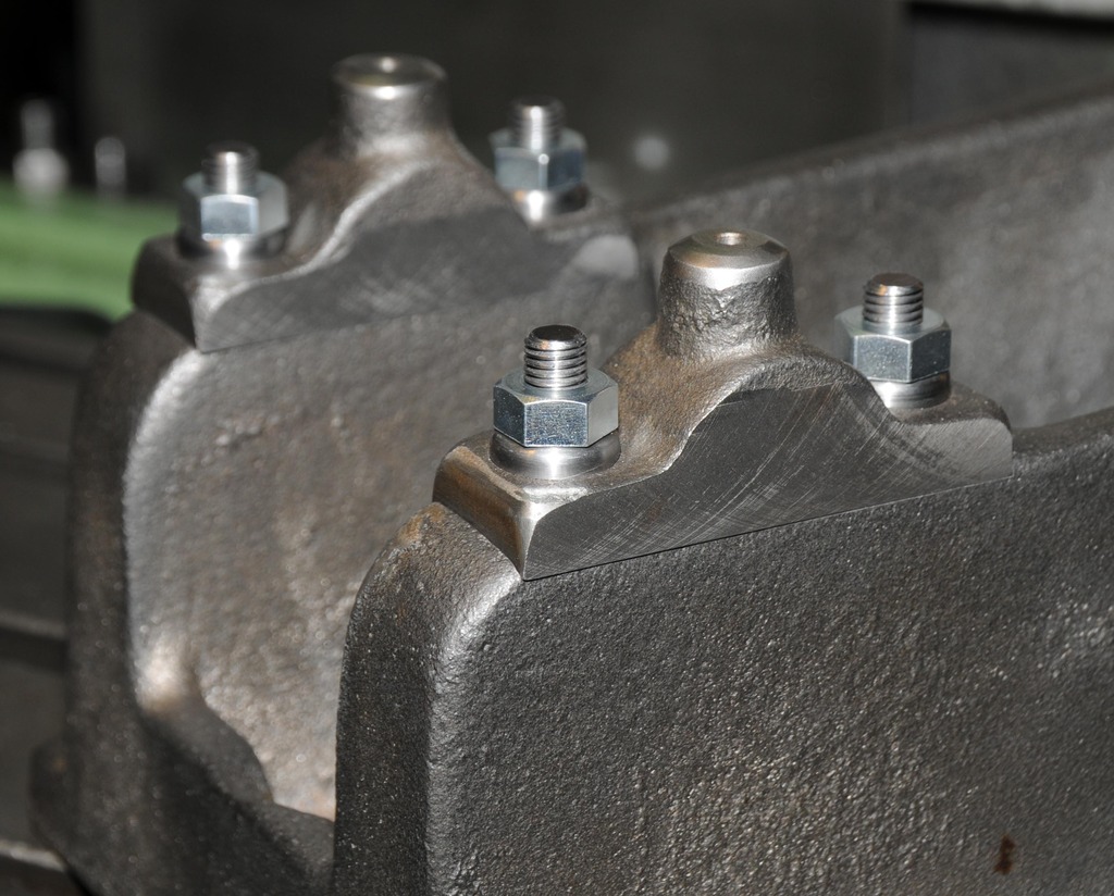
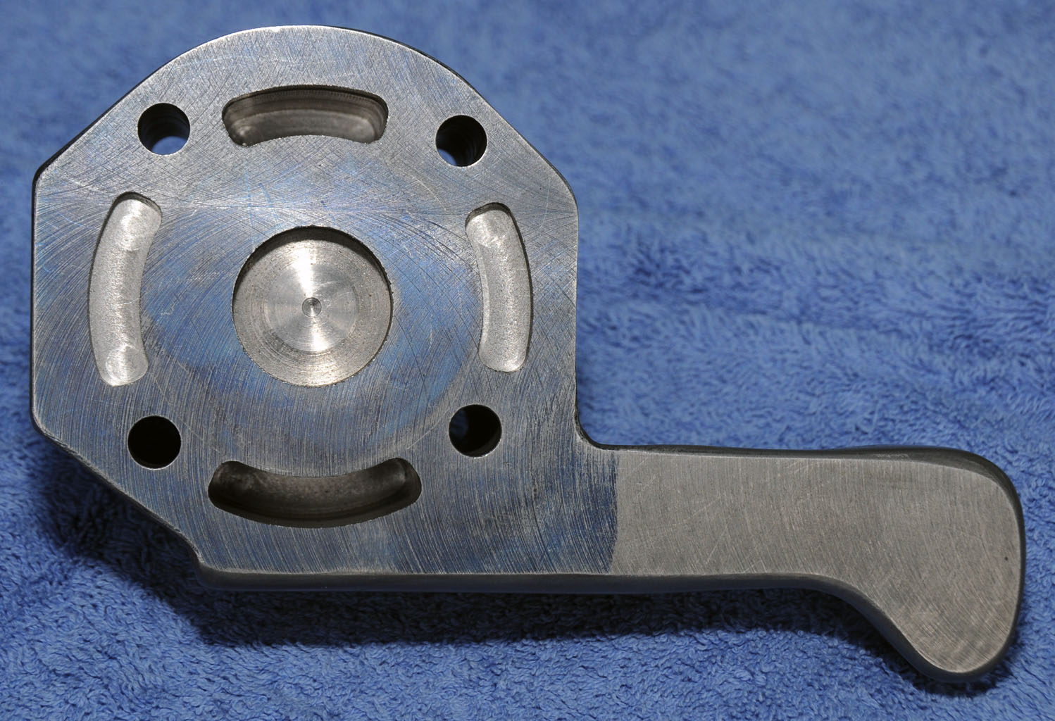
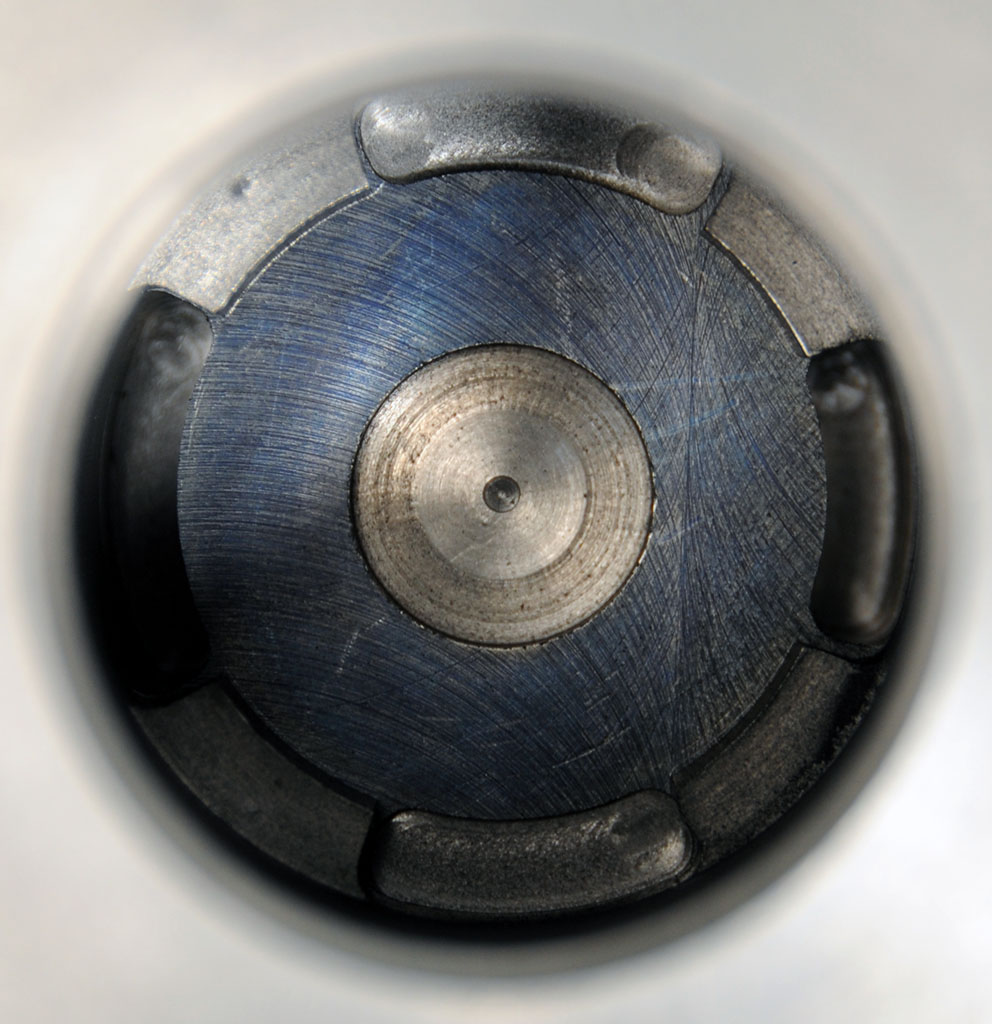
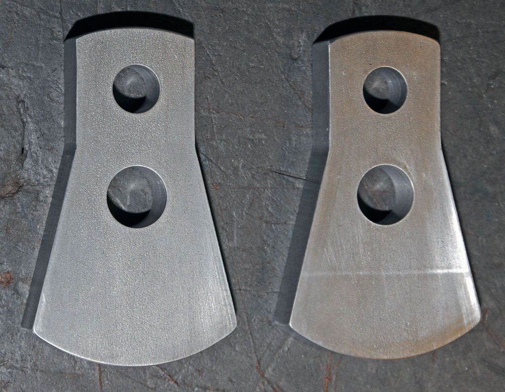
Finished bearing caps.
Going back a few years a mate of mine (Len) decided to design and build a scale model stationary engine loosely based on one of the full size engines in his collection. He made all of his own patterns and even had a crack at doing the casting himself before deciding to get this done at a foundry. The story of how he designed and built The Billabong Engine (as it’s named) can be found on his website and is worth a read if you get a chance: http://members.iinet.net.au/~hoppi/MakingABillabongEngine.html
In January 2014 he was getting some castings done for a steam engine and asked me if I would like to get a set Billabong engine castings done at the same time and of course I jumped at the chance. After picking the castings up from the foundry they sat in a box for a few months and it was not until April 2014 that I started to do some work on them. This will be my first model engine build and is going to be a long term project. Given that I started on this a year ago now these first few posts will cover the work done since then and may give the false appearance of rapid progress. Unfortunately this is an illusion and progress has been slow however I endeavour to keep working away on it and will post updates as things progress.
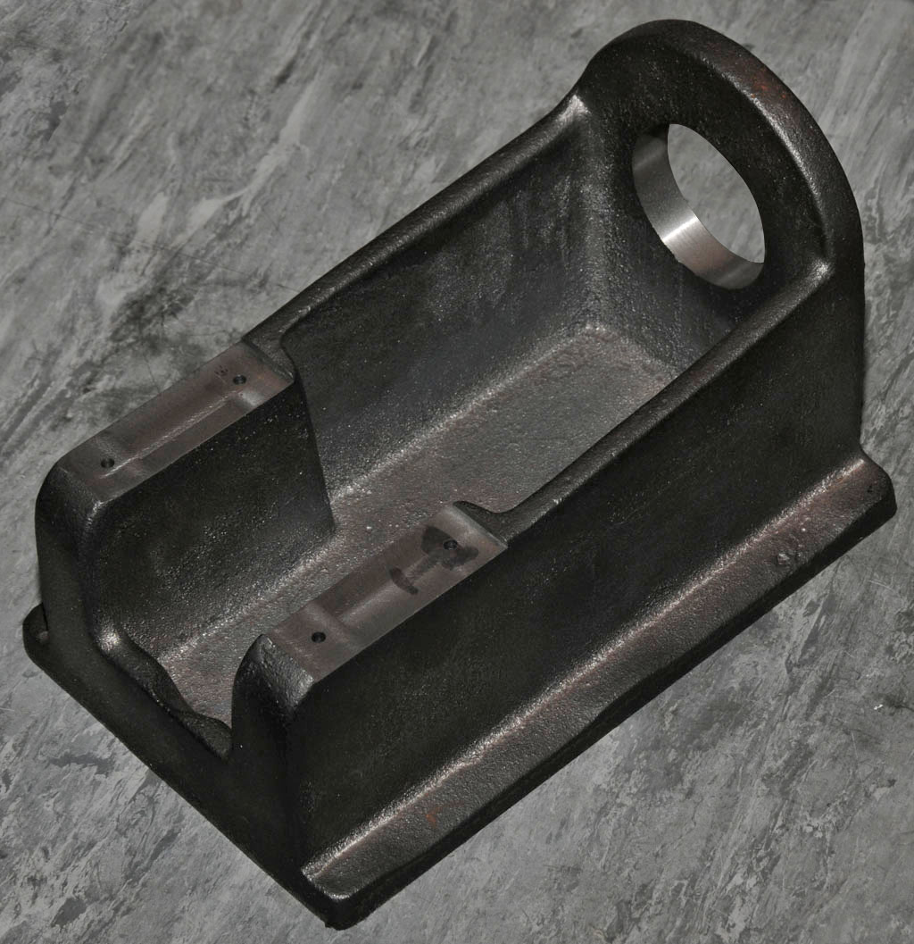
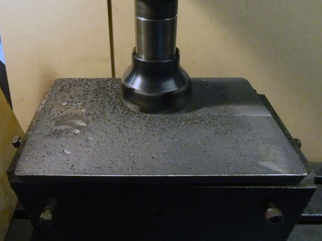
First job was to machine the bottom of the crankcase casting which will become the reference surface. The crankcase doesn’t have another surface parallel to its base so Len had made a fixture (which I borrowed) to support it so as to avoid messing around with jacks and packers. Just enough material was machined from the bottom of the casting to make an even surface which only required a couple of .020” passes to complete.
Base casting and support fixture.
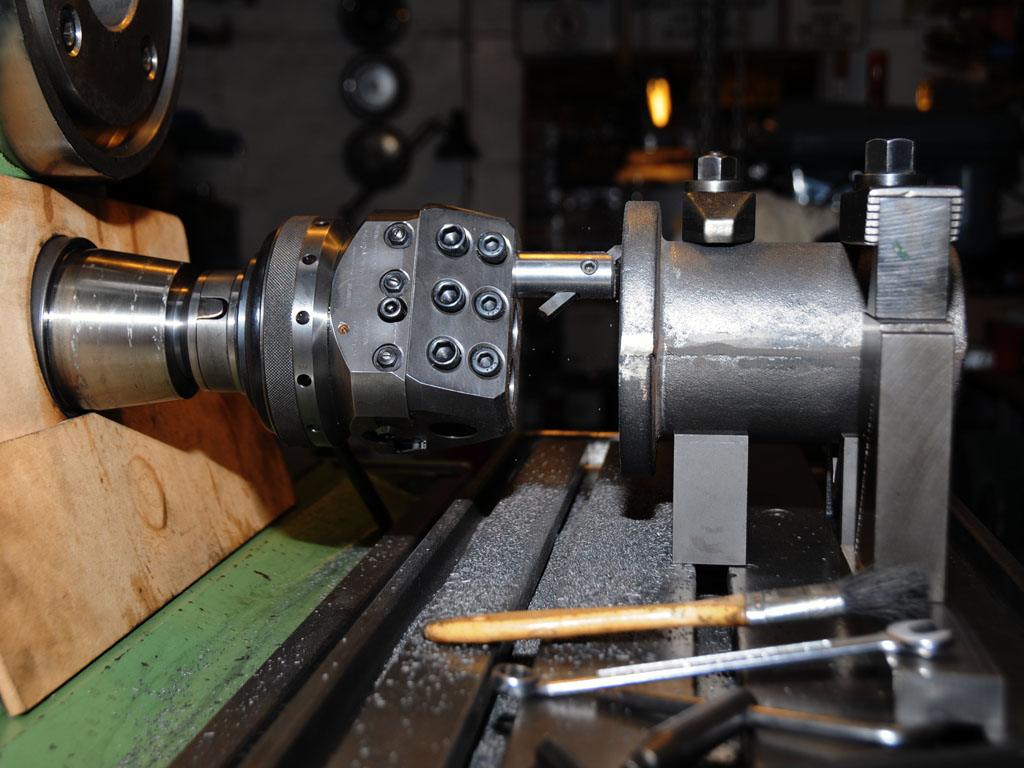
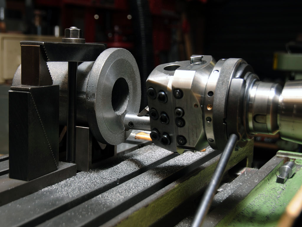
Machining the base.
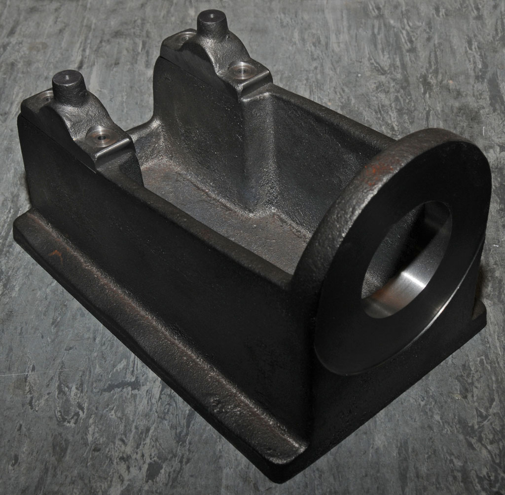
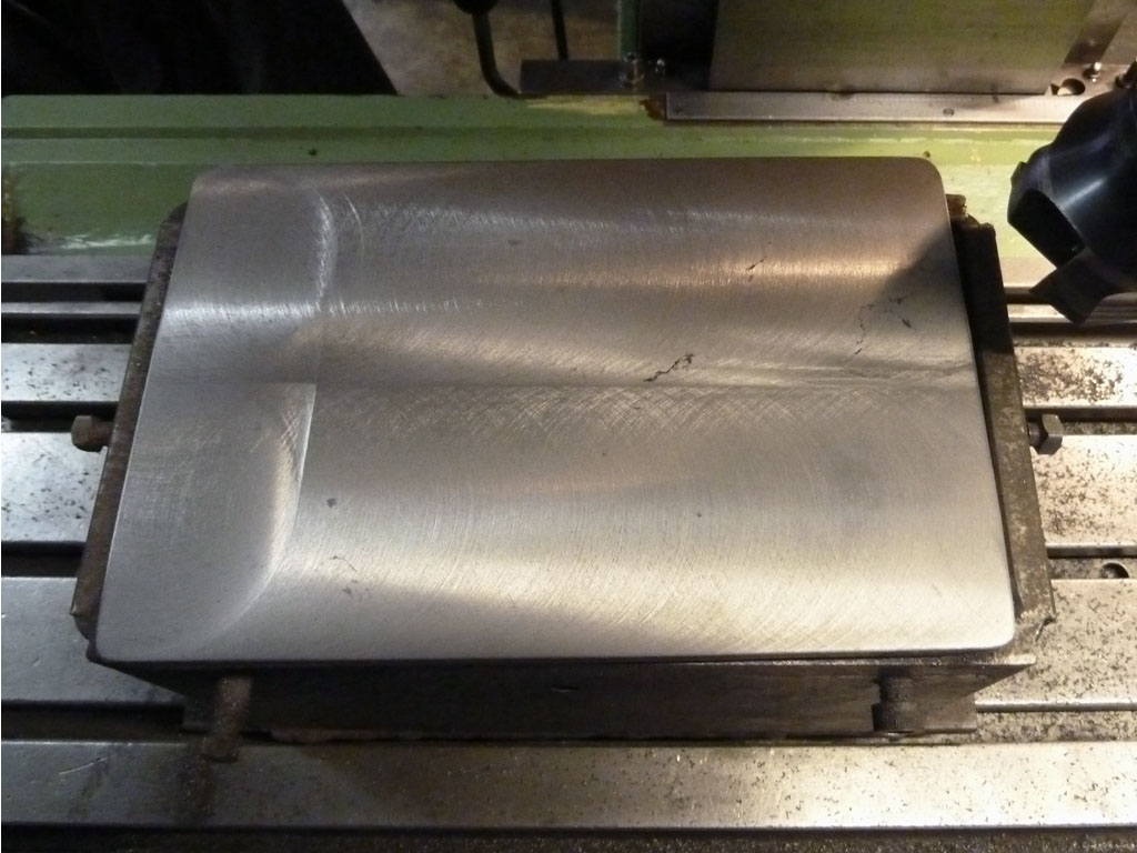
Job done.
Main Bearing Caps
The main bearing caps needed to be finished to final dimensions so the seats in the base casting could be machined to a matching snug fit.
The first cap was clamped on its side in the vice and indicated in as even as possible before making a couple of clean up passes. The cap was then flipped over and positioned on a parallel so the other side could be machined flat and the width bought to a size that would fit neatly on the crank case. This process was then repeated for the second bearing cap.
I should probably mention at this point that there are no detailed plans or drawings for this engine, Len gave me a copy of his notes which includes hand sketches of the major components with indicative dimensions but nearly all of the machining needs to be done by the seat of your pants. This offers a lot of freedom but also means that careful thought needs to be given as to how work done on one component will affect its fit to another that may not yet have been machined. I have heaps of photos of a finished engine to refer to and will be able to discuss things with Len on the phone if necessary but the rest is pretty much up to my imagination
With the sides of both bearing caps now parallel they were clamped together in the vice so they could be machined to their final length of 2.625”. Both caps were then mounted together with the bottom facing up and the shoulders bridged across a couple of parallels and the bases machined to bring them to a height such that they would sit aesthetically on the crankcase while leaving enough meat to bore later on for the crank bearings.
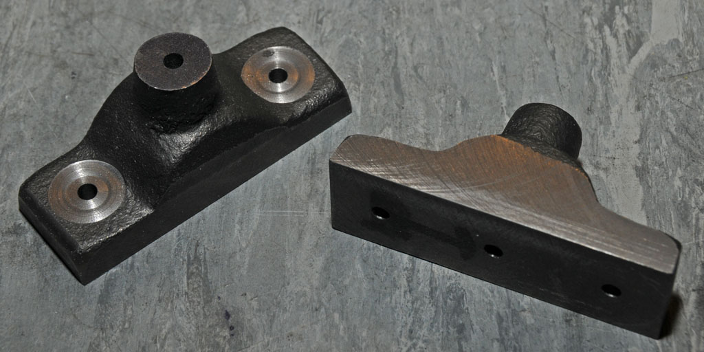
Finally they were flipped over and positioned on a parallel so the tops of the oiler bosses could be machined flat. The positions of the bolt and oiler holes were then marked out, spotted with a centre drilland pilot drilled to 4mm. The bearing cap castings don’t have bosses for the retaining bolts so each mounting hole was counter-bored with a 16mm slot drill just enough to allow the mounting bolts to sit flat.
Unfortunately I didn’t take any photos of this process and apologise if this is a bit wordy.
Finished bearing caps.
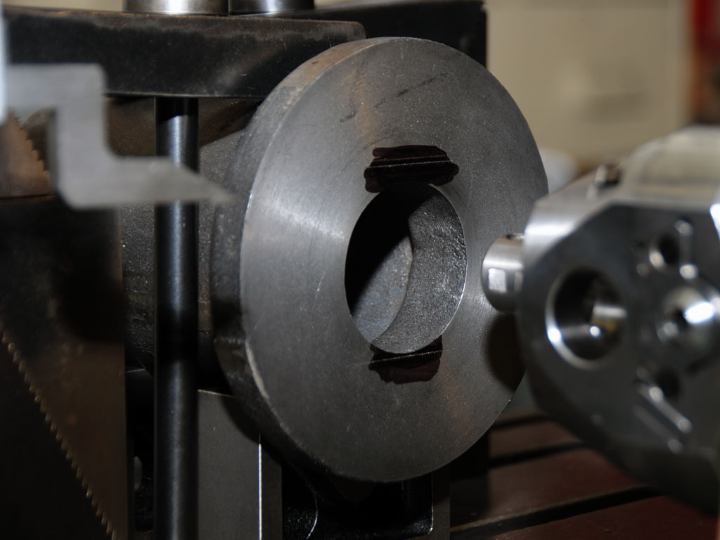
") the centre of the crank would end up sitting about 0.125” below the centre of the cylinder. I don’t know if Len intentionally designed this engine to have a D
the centre of the crank would end up sitting about 0.125” below the centre of the cylinder. I don’t know if Len intentionally designed this engine to have a D