Brian Builds the Kerzel Hit and Miss I.C.

Home Model Engine Machinist Forum

Help Support Home Model Engine Machinist Forum:

This site may earn a commission from merchant affiliate links, including eBay, Amazon, and others.
All good things must come to an end, and I think I am going to end this thread on a positive note. Its been a great learning experience, I have built my second I.C. engine succesfully, and it does run in hit and miss mode. Not as nice as some I have seen, but hit and miss, none the less, and I have got it to run much slower. Further running may show me a way to get it to hit only once instead of multiple times between misses, but for now I am about 95 percent satisfied. If I ever get it to run as good as some others I have seen on this forum, I will definitly come back to this thread and post a video. Thank you to all who hung in there for the duration of this gigantic thread and offered advice and encouragement.----Brian
 
Real Great Job Brian! All together this thread in very educational.

You have built a engine to be proud of, I for one really like the wood base and all the do-dads on the engine.


Kel
 
I agree, it running at all is a massive achievement in my eyes, but the fact that it runs as sweet as a nut now, and in hit & miss mode is superb. Well done Brian, everybody has enjoyed this greatly.

Nick
 
Brian, I have sure enjoyed everything about the long and learning post you have a lot to be proud of, I think it was a great success I learned a lot and learned that I am many hours of every Trying something like that, it looks good runs good, thanks for letting us see it all, Lathe Nut
 
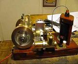
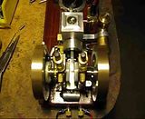
Although this is not really a "Work in progress" at this point, those of you who followed this thread may find this of interest. As you may remember, the main bearings for this engine were originally made from bronze. To my dismay, (and puzzlement) they wore out before I even had the engine running. I built a second set of main bearings from brass, and they seemed to work fine. This was very curious, because bronze is a far superior bearing material. I have ran the engine a bit every day, as I am rather intrigued by it, and now, Lo and Behold, the brass main bearings have gone the way of the bronze main bearings. They are severely worn, and you can actually grab a flywheel and "wiggle" it around due to the slop in the bearings. The bearings have lubricators on them, and I can see that they are using oil, so lack of lubrication has not caused this problem. I can only conclude that my built up and silver soldered crankshaft must have enough "distortion" in it to cause this accelerated bearing wear. I now have to come to some reasonable fix for this situation. I could build another complete crankshaft, but seeing as the 7/16" bearing bosses are actually machined seperately as sleeves and slid onto the 3/8" diameter crankshaft and loctited in place, I may try another approach. The existing crankshaft still has the countersinks in each end that were used to turn it between centers to clean up excess silver solder. I may heat up the existing bosses to break the loctite bond, slide them off, and install new bosses 1/2" in diameter and loctite them in place. After a 24 hour cure time, I will then set the crankshaft up between centers and using a lathe dog to transmit torque, turn the new sleeves "in place" to the required 7/16" diameter. That, along with another set of main bearings SHOULD solve the worn bearing issue once and for all.---Brian
 
Hi Brian
Its hard to imagine how a shaft which has run-out or is not running true could possibly spin freely in an engine, if you had ,say 2thou run-out and 2thou bearing clearance of course it would bind. You say you still have the centre drillings in the shaft
maybe you could mount the shaft between centers and confirm (or otherwise) any distortion with your trusty dial indicator ;)
Stew
 
Stew--I definitly will do that before I make any attempt to modify the crankshaft. Set it up between centers and run a dial indicator on both bearing surfaces. If there is no discernable "out of true" condition in the crank, I certainly don't want to go to the work of modifying it.-----but that will leave me scratching my head about what is happening to my main bearings !!!
 
I have this saying that if it won't bounce it won't run. What I mean is if you flip the flywheel against compression will it bounce back or just wheez out the compression? If it won't bounce back it won't run well. Also, who ever suggested choking off the intake with a restricter has it right too. An engine that size could run well, slowly that is, with about a 1/16 air intake. Try a choke tube in the intake with a 1/16 hole in it. Its easy to make one up. Maybe a piece of tape ove the intake with a pencil lead hole would be a good way to test that theory.
 
Metal Butcher has me thinking (Which is not always a good thing) about an adjustable position for the point at which the "hit and miss lever" engages the pushrod to hold the exhaust valve open. On the original Kerzel engine plans, there is no provision for this adjustment, which has caused me no end of grief in getting things set "just right" for the point at which the hit and miss action begins to take place. I am bored today, so I spent a bit of time coming up with a way to make this adjustment possible on my engine. I did have an earlier design in mind, but it was simply to crowded to implement. I'm not sure I will build this, but boredom and lack of projects to machine does terrible things to me, so this may happen.---Brian
HIT-MISSLEVERLAYOUT.jpg
 
Oh no! I wasn't trying to cause you any trouble Brian. Thinking always gets me in way over my head. scratch.gif

That's a really nice adjusting mechanism you came up with. I like it a lot! You should be able get a real 'fine' adjustment with out any problem using that system. If I may... I would suggest coming up with a design to make the push rod adjustable too. I think that this would allow you to control the length of time that the exhaust valve stays open.

-MB

 
The push rod already has some adjustment where it screws into the block at the end. You could get a bit more by installing an adjustment screw in the outboard end of the tappet.
 
tel said:
The push rod already has some adjustment where it screws into the block at the end. You could get a bit more by installing an adjustment screw in the outboard end of the tappet.

Hi Tel, thanks for pointing that out. I can see where it must be threaded into the cam follower in Brians last post of a drawing.

On the Upshur there is no adjustment on the 4-stroke versions. on the hit-n-miss versions a clevis is added to the out board end of the push rod, but the plan calls for the use of Loctite for attachment with no way to adjust it. So to add an adjustment feature, I threaded the end of the 3/32" push rod and tapped the clevis 3-56 to solve the problem.

Sometimes plans leave plenty of room for creativity, and most of it is due to a need for improvements.

-MB
 
Hi Brian, I'm exhausted just from following your build story. Congratulations many times over.
Ian.
 
Tel is correct. The pushrod screws into the block with the follower bearing on it, and that is how you adjust for valve lash. I have found that the optimum setting is about .005 to .007 "free space" between the end of the pushrod and the rocker arm when the follower bearing is not riding "up" on the cam. The model I did up and posted yesterday would depend on the pushrod not being able to rotate. In practice, without a jam nut to hold it from rotating, the pushrod will quickly rotate itself out of spec when the engine is running. Rather than fab up a locknut, I put a bit of loctite on the thread and set it at the correct position. I like this method of adjustment I have designed, because it is all "bolt on" and I don't have to mess with the integrity of the existing engine package. ----And as Tel pointed out, if I want to maintain some adjustment of the pushrod length, I can put a screw into or threaded sleeve over the end of the pushrod that contacts the rocker arm.
 
I did my rod with 5BA thread, a little longer than called for, and use a one-size-smaller 5BA nut to lock it. Adjusted it to around 0.005" tappet gap, bur haven't seen the need to fit an adjusting screw (yet).
 
My engine will start out very easy when its cold, and the hit and miss function works quite well, although I have never yet been able to get it down to a single hit between "miss" cycles--it always hits 3 or 4 times.. After 4 minutes of continuous running, you can see that the engine is stiffening up, to the point where the RPM's start to drop off and it doesn't go into "miss" mode anymore. After another two minutes of running, it slows down and stops. At that point if you try and turn it by hand, it is quite "stiff" to turn. After an hour of cooling down, it turns freely again. I assume from this, that the cylinder barrel is heating up and "crowding" the piston, even though the cooling reservoir is filled with water. When I built this engine, I put 2 Viton o-rings on the piston. It has mega compression with the head removed and a solid blocker plate bolted on in place of the head. (I discovered this while trying to sort out my lack of compression due to non-sealing valves.) Now, looking at this in retrospect, I am beginning to think that perhaps the drag created by 2 o-rings is the culprit which keeps my engine from going into a true hit and miss mode where the engine only fires once between misses instead of hitting 3 or 4 times. It may also be the reason for the piston beginning to "freeze" in place after the engine runs for about 6 minutes. I suppose my next logical move would be to remove one of the Viton o-rings without changing any of the other settings to see what the results would be. I would like to hear some input on this from others who have built "succesfull" hit and miss engines using Viton rings please.-----Brian
 
My piston is aluminum. The cylinder barrel is stainless steel. I used Viton because I am an amateur machinist and I din't think I had enough knowledge to make my own rings. The concept of a brass piston ring is interesting. I haven't heard of that before. On Metalbutchers wonderfull post about making his Upshur engines there is some good info on making piston rings. I will give that another look.
 
Hi Brian
This writer had an old model maker say that using two o rings was a bad idea because pressure could build between them and cause a problem like you describe. fwiw, a friend in models, Jim Hay
 
There's lots of ways to make a ring but lots of guys make them the exact diameter then clip them to create the break. I then lay mine on a 1/4 inch plate of steel, place a spacer in the gap, and heat the steel from underneath until the ring relaxes. It works for me. I think getting the height really close to equal with the groove is important too, 0.0005 or about. Its not easy to get a good ring, at least not for me, although I can do it. I make mine from cast iron.
Be reminded too, a ringed piston requires a good cylinder, straight and round. I'm not talking about just close to straight but really straight and round.
 
This morning I decided that before I got too crazy (crazier??) about making a new cylinder liner and piston from grey cast iron, I should really try this engine with one o-ring to see what difference it would make with the friction in the engine. I pulled the engine apart, removed the second ring down from the top of the piston, and while I had it apart I chucked up the piston and turned the groove for the remaining o-ring about .010 smaller on the diameter. While it was apart, I got out my polishing buffs and polished the water jacket/cylinder body and the rims of both flywheels. One thing I was surprised to see was that there are no rub marks on the piston at all----the entire piston is "floating" concentric to the cylinder, held there by the Viton o-rings!!! the removal of one ring and the deepening of the remaining groove makes an incredible difference in the "stiffness" of the engine, yet I still have loads of compression. The engine now runs much more freely, and swings in and out of hit and miss mode much more readily than it did before. I haven't had time to try an "endurance run" yet to see if this new "freedom" will make a difference in how the engine seemed to be heating up and dragging on the piston after a 5 or 6 minute run. (I've been running it on the corner of my desk in my engineering office), and not only am I getting yelled at by the wife for stinking up the house, but I don't want to gas myself. Tomorrow I will take the engine out to the big garage and try an endurance run to see how long it will stay running.
 

Latest posts

Back
Top