ball milling

Home Model Engine Machinist Forum

Help Support Home Model Engine Machinist Forum:

This site may earn a commission from merchant affiliate links, including eBay, Amazon, and others.

scoop

Well-Known Member
Joined
Nov 29, 2008
Messages
83
Reaction score
1
Just recently there has been a fair bit of activity in the ball turning area.This reminded me of my apprentice days where one of our test pieces was a sphere that had to be cut on the end of a shaft but done using a milling machine.Because of the importance of hand skills and basic equipment back then our instructors usually found the most awkward ways to get us to produce items rather than the quick easy ways.If anybody is interested or if they have not done one before on a mill before I could try to remember how we did it and post the method.This was the one and only time I ever made a sphere on any machine and just as much importance was put on the maths involved(very basic)and the setting up(not quite so basic)as the end result.

best regards Steve C.
 
I did those too about 30 years ago, and IIRC it was because our instructors mate had just started to play 'petanque' or 'boules', and needed a load of large-ish aluminium balls. ;D

The technique used a angled flycutter in the mill spindle, sort of similar to an old fashioned cranked turning tool, with the working end facing 'in' towards the spindle centreline, and the lump of metal on the end of a shaft, set in a rotary table/dividing head chuck angled up at 45 degrees.
The flycutter width was set the required ball diameter, and centred over the square lump of material. The rotary table/dividing head was then turned continuously while the cutter was brought into the cut in small increments.

In this way, every point on the sphere passed under the cutter, and it wasn't long before you had your balls.

Peter
 
yes peter thats pretty much the same way.Did mine back in 1976 and probably still have the test piece kicking about somewhere.You must have been around when stuff like that was all the rage.I just had not seen or heard of anybody else doing it that way for ages so I thought I would see if it was commonly known.Looks like south east England is up to speed.

Best Regards Steve C.
 
I don't remember the exact set-up Steve, but I seem to remember now that there was a bit of offset involved somewhere.

If you can remember the details, I for one would be happy to have my memory well and truly jogged, and I think it would make for a very interesting post, especially if you can remember enough to do it all again with some pictures.
I reckon you should go for it and post the whole method.

Peter

 
because our instructors mate had just started to play 'petanque' or 'boules', and needed a load of large-ish aluminium balls.
You may have produced those balls for him, but aluminum would never hold up for petanque: too soft and too light.
 
Here's the layout. I had the picture on my hard drive from a while ago.

ball.jpg


JS.
 
Here is an explanation of how.

first a dodgy drawing
DSCN2390.jpg


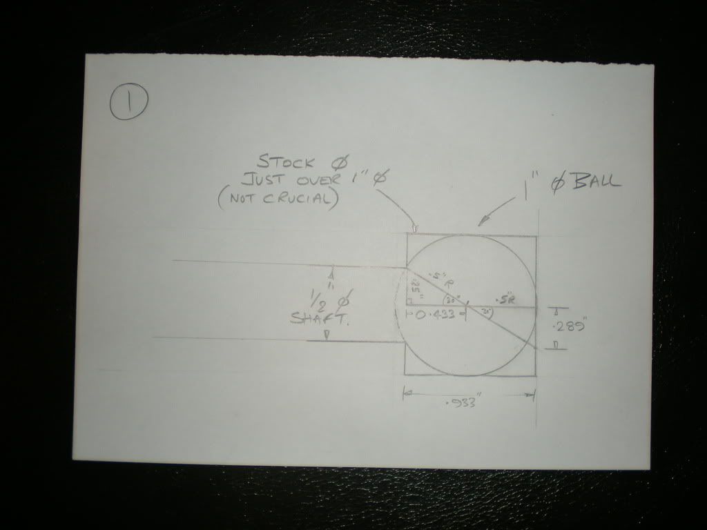
I will assume a 1" ball on a 0.5" shaft.looking at the left hand triangle within the ball using pythagoras work out length of bottom line of the triangle.This is 0.433".Add this to the top edge of the triangle on the right hand side(0.500") to give 0.933".This gives you the length of the amount of full diameter stock to leave on the end of your 0.500" diameter shaft.Trig out the angle between the ball centre point to the shoulder intersection(0.500" rad),and the 0.433" long lower line of the left hand triangle.This is 30 degrees.From this trig out the length of the vertical line on the right hand triangle.This is 0.289".

now another even worse drawing
DSCN2391.jpg


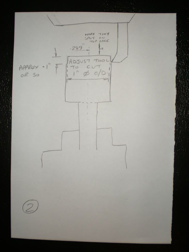
turn your blank to size.ie .5" shaft and .933" length of full diameter stock(about 0.020" over 1" is ok).load up in the tilting rotary table chuck on mill table and set pointing up vertically.Set x and y zero true to stock diameter and then move over 0.289" in x and put a spot on top face with tiny centre drill(only need to just touch it)for this set up I am assuming that the usual axes are being used on the mill ie x left to right y in and out and z up and down(not very technical I know but hopefully self explanatory).
Go back to x and y zero and set up fly cutting tool to cut a 1" diameter O/D by turning down outside of stock along z axis(only a short distance of cut is required just to set diameter).

Last drawing I promise
DSCN2392.jpg


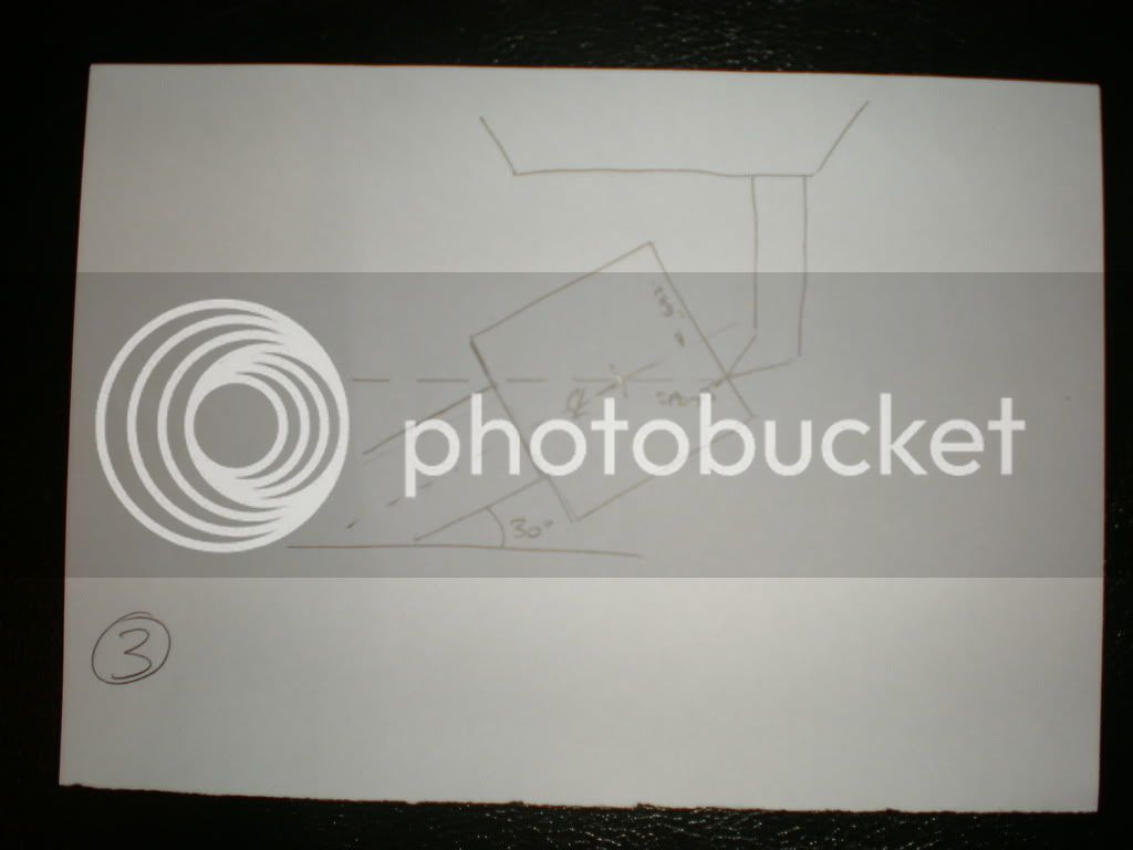
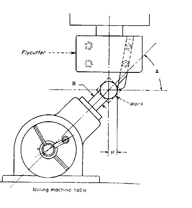
tilt table over to 30 degrees from horizontal so that shaft is running along true to x axis then move cutter over in x and down in z and pick up small spot marked earlier as shown in drawing 3.If all is ok y axis should still be true to stock diameter.Make a note of z axis value as this is the full depth of the cut.It should be noted that the shoulder between the full size stock and the shaft diameter,the centre point of the finished ball and the small spot marked on the end face should all be in a straight line par allell to the mill table.Raise up away from blank,check for clearance all round and switch on spindle.wind down in z until cutting then rotate chuck 360 degrees.You should have a complete cut all round the stock diameter (not anywhere near a ball but a machined witness).Drop the z a bit more and continue to rotate the chuck until you reach the full z depth set earlier and your ball should be complete.Some of the cuts may be a bit heavy as you get deeper but adjust to suit the strength of your set up.

this has gone on far enough now.Hope it made sense.Maths bit is not to tricky and should work for any combination of ball and shaft.The rest should be pretty obvious as you progress.You probably won't because its a pain in the arse,I know I won't be doing one cos I will make a ball turner and do it in a fraction of the time.This was just a task set by a nasty old instructor to scare young lads and should be left as such.

best regards Steve C

p.s. this is my first post with pictures so I know it will go wrong,when it does please bear with me cos i'm old.
 
scoop,

Thanks for the explanation (the drawings served the purpose quite well) of this. Like you, I'd much rather build a ball turner, but it's still interesting to see how it could be done.
 
Scoop

Thanks for the time you took for the drawings and the explination.

Never knew it could be done in a mill. Learned something new again.

Bernd
 
Saw a video sometime in the past, where a similar method was used to cut a parabolic (concave) mirror surface. Same basic principle but the cutter was positioned offset from the work piece so the cut was made with the outside edge of the cutter.

Steve
 

Latest posts

Back
Top