Atkinson Cycle Engine Supersized

Home Model Engine Machinist Forum

Help Support Home Model Engine Machinist Forum:

This site may earn a commission from merchant affiliate links, including eBay, Amazon, and others.

Tom T

Well-Known Member
Joined
Sep 22, 2007
Messages
121
Reaction score
20
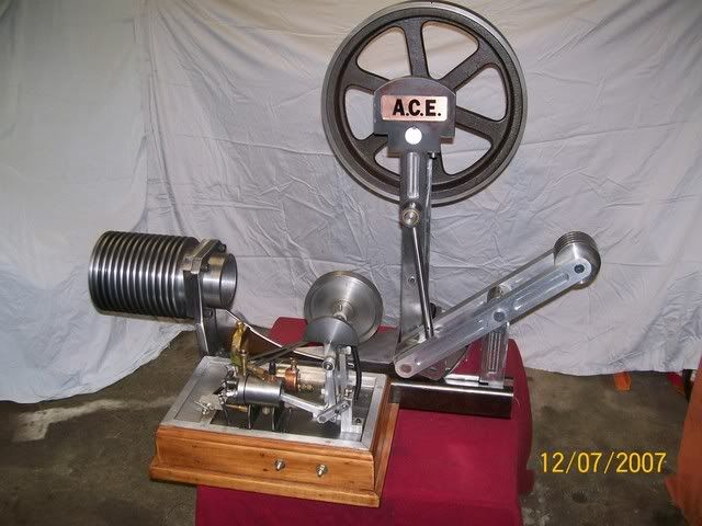
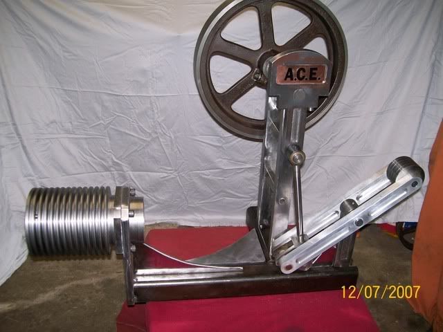
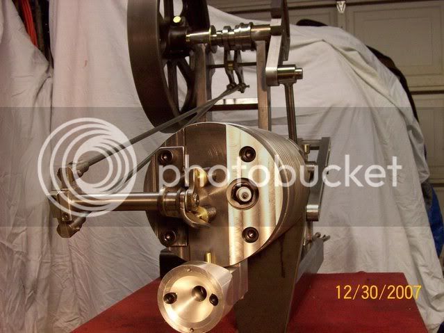
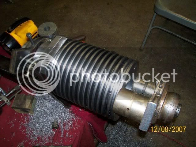
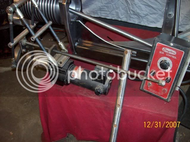
I have started a new project and thought I would share it with you. I am building a large Akinson Cycle Engine to power a small ride on tractor.

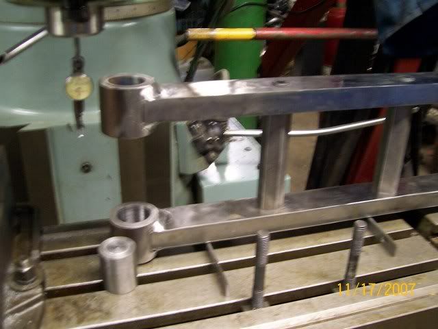
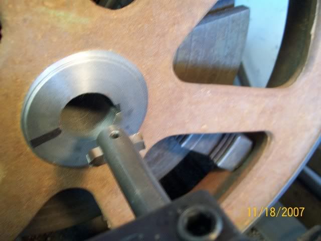
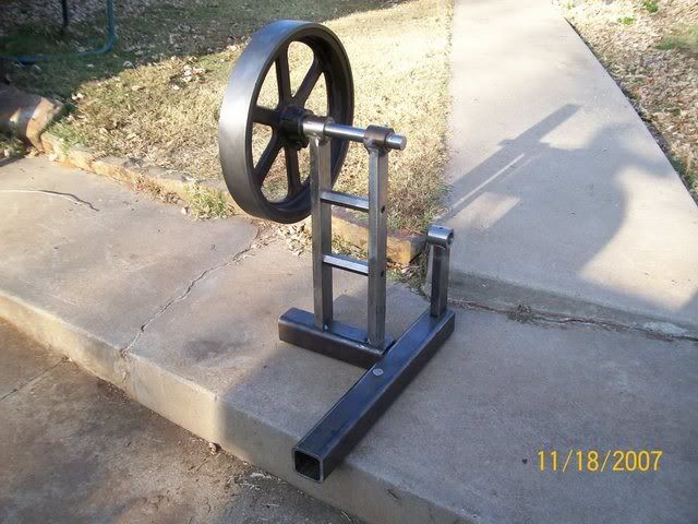
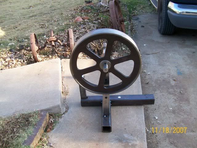
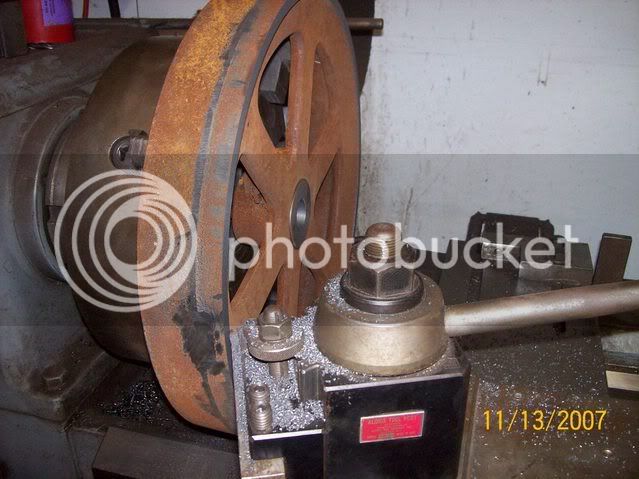
What I have is a flywheel that I am going to build a engine to fit . :roll: I have the frame all most done and will post pictures when I get it further along. Here is a picture of the flywheel it was a raw casting . I hade to grind the spur off of the outer rim to get it to fit in the lathe.The flywheel is 18" dia. 57 lbs. Is this a model it is being built from bar stock?
Tom
100_1443.jpg
 
Tom,
Of course it is a model, just a little bigger than normal.
I like your logic by the way, it's like "I found this tail light, I will build a car to go around it", great way of thinking.
Love to see it as it progresses, keep us posted.

John
 
Tom,

That looks like the one on the tractor picture in my book. Page 41.

The book I have is called; The Agricultural Tractor 1855-1950 by R.B. Gray.

Kenny
 
Kenny I ran and got my book thinking you solved the flywheel mystery what was it made for. Thats the picture I used to build the model tractor. your right its close Tom :)
 
Tom,
After looking at it in your lathe (several times), it sure looks like the exact flywheel on page 67 top right corner showing the oscillating magneto. But I can't figure out what engine its on. Does it have those casting marks like the ones on the spokes in the picture?

Kenny
 
Kenny the engine looks a lot like a 8-16 mogul. the first ones had a sheet metal water hoper. and they only had one flywheel. my flywheel has no casting marks .I think thats where the belt pulley bolts on. I will post more picures on this project soon. Tom
 
This is picture of the crank bearing holes being bored. After the bosses where welded on they needed rebored for good alignment. I first bored one end and made a dowel pin with threaded hole in the end to fit a T nut. I installed the dowel pin and indicated it in. Slid the bored end over it and bored the other end. This worked out good This is a trick I learned from the Henry ford plans. sorry about the bad picture

101_0343.jpg


This picture shows how I cut the keyway. By advancing the tool and cranking the carriage back and forth what seemed like a hundred times.

101_0347.jpg


This is a picture of it tack welded together for a trial fit. I know it needs more bracing and some bling :lol:

101_0354.jpg

101_0350.jpg
 
I made a little progress on this project. The cylinder bore needs finished, its a little rough. I bored it in the lathe with a 12" boring bar. The bore is 11" deep by 3.75 bore. Its to big for the mill. How would you clean it up? It needs about .150 taken out of it. The boring bar is not rigid enough.

I really like the new site. You guys did a great job. Thanks to all who made it.
Tom
101_0374.jpg

101_0370.jpg
 
Goodness me Tom, that is starting to look rather impressive.

That is a long way to have the boring bar sticking out, no wonder it isn't rigid enough.

There are only two ways I can suggest, the first is to make a more rigid bar, use 1.5" diameter if need be (you have enough diameter spare in the bore), weld a square bar on the side to hold it in your toolpost. You can always recycle it afterwards for making other bits.

The other is to mount the job on the cross slide and use a boring bar between centres, but that would require some very careful shimming and setting up. This would give you the same sort of action as if you were boring it on the miller.

Maybe some of the big machine or production guys can come up with an easier answer for you.

Best of luck with that one.

John
 
That is looking real good Tom.

A larger dia. bar is all I can think of too.

Kenny
 
Thanks for the post Bogstanderd and Kenny. I mounted a bearing on the ends of the cylinder and bored it out with a portable boring bar
Here are some pictures of the carb. cylinder head,rocker arms,pushrods,cam.
enjoy Tom T
100_1511.jpg

100_1513.jpg

100_1517.jpg
 
Looking good Tom! How does a portable boring bar work? Never seen one of those.

Wes
 
That is really taking shape, Tom. I love the way you did the inner and outer rocker arm shafts.

Kenny
 
That looks awesome. My personal interest is in large "model" IC engines. I haven't built any yet but I'm working on it. You definitely work quick. Is it difficult to make a functional carb? I haven't been able to find any good info on building one online.
Looking forward to seeing some videos of that one running by the end of the week:)
 
Heck of project, Tom. Happy to see you aren't letting up!

I'm studying your Carb pictures, since I have an upcoming task to build one for my Open Column twin. What is the purpose of the ribbed nipple coming in at an angle beside the needle valve adjustment screw? It appears to me that the brass tube opposite the adjustment screw is the fuel line connection.

Thx...
Chuck
 
Thanks everyone for your nice comments.

Kenny, the rocker arm shaft was taken directly from the Atkinson cycle model plans and enlarged.

zeusrekning, I would like to have it done by the end of the week but big parts take a long time to make and take up a lot of material. 8) I probably could of built 3 or 4 small models in the time it has taken me to build this. But I think it will be worth it.

cfellows, the ribbed nipple is the fuel line attachment and the brass tube you are seeing is the butterfly shaft [throttle] I pulled the carb of off a old international LB engine that was throttle governed and built this one from looking at it. I don't know yet how well it will work. It has no idle circut. The barbed fitting has a drilled passage that comes in just behind the needle valve. The needle valve is drilled thru to the smallest part of the vintura.

Powder keg, here is a picture of the bearings mounted to the cyl. The boring bar is slid thru the bearings, and the drive unit is slid over the bar and the outer part of the bearing and clamped. The bar is fed in by turning the all threaded shaft. This is a home made drive unit that I built several years ago. A guy could build a smaller one of these and use it to bore the crank shaft bores on a model engine. You could power it with a slow speed drill and just push it thru.


101_0382.jpg


100_1519.jpg
 
Hello Wes,
Here is a little update for you. I boxed in part of the frame and made a gas tank. Built another cam, rocker arm and push rod for the points. Built the exhaust system. Then I completely disassembled it and added gussets and mounts. Welded all the joints. Sanded and primed it. Cut red oak to cover the base. I weighed all the parts and came up with a total of 275 lbs. Maybe it won't jump around to much. ;D

After seeing all the nice projects on this forum I thought I'd better add a little more detail and bling. When I get it reassembled I will post pictures. Tom
 
Glad to see you are making progress:O) I still don't quite get how that boring thingee you have there works? Maybe you could elaborate on it a bit, please?

Thanks, Wes
 
Back
Top