


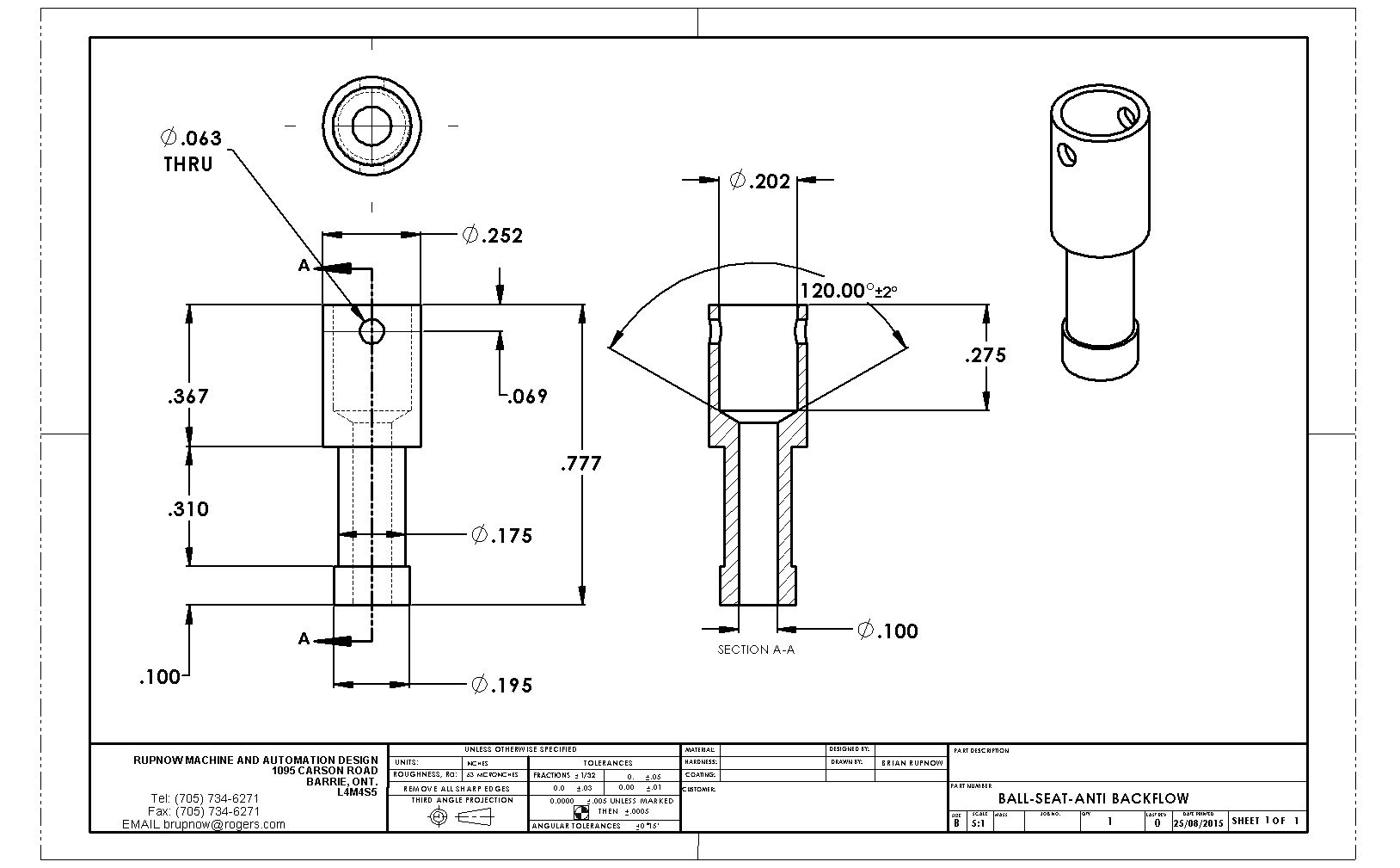
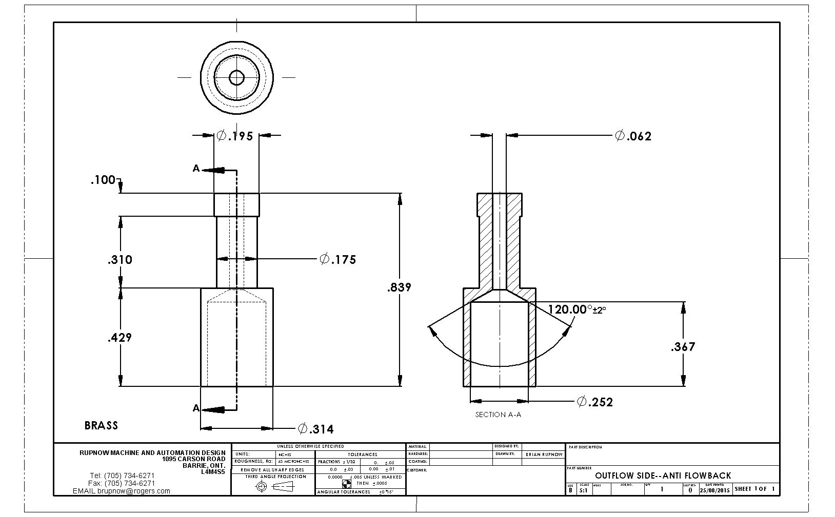
If you play around with model hit and miss engines, and are successful in getting them to "hit" once or twice and then go into 5 or 6 "miss" cycles before firing again, you will see a strange phenomenon (if you have transparent fuel tubing.) These carburetors on these engines suck fuel up from the tank, and the suction is created by Venturi effect in the carburetor air inlet. As long as the engine "hits" more than it "misses", the fuel line will stay full of fuel. However, when you get the governor weights adjusted to the point where the engine does go into a long series of misses, very little air is sucked through the carburetor during this time (The exhaust valve is held open during "miss" cycles). As a consequence, not enough Venturi effect is being created, and gravity will make all the fuel in the line run back down into the tank.Then when the engine finally does try and go into a "hit" cycle again, there is no fuel in the line and the engine will die. to prevent this happening, an "Anti backflow valve" must be placed in the fuel line somewhere between the tank and the carburetor. This is a simple ball check valve, that will allow fuel to be sucked up to the carburetor (the ball lifts off the internal seat letting fuel flow by it, and when there isn't any "suction" being created in the carburetor, the ball falls back under the influence of gravity and seals against the seat, thus stopping fuel in the line from "back-flowing" under the influence of gravity. I just built one for the oscillating i.c. engine I am currently playing with, and here are the plans for it. It works best when installed in a vertical manner in the gas line, and it doesn't make much difference if it is closer to the carburetor or to the tank. The only "trick" involved with this, is that after the part which has the actual "seat" for the ball machined into it is made, set it on a hard surface, insert the ball into the top of it, and using a flat ended punch and hammer, give the ball a good solid "whack". This will make the seat conform to the exact shape of the hardened steel ball (mine is from a ball bearing) and provide a leak-proof seal. If you get a good 'sliding fit" between the two machined pieces, seal them together with Loctite. If the fit is a bit sloppy, then use J B Weld--just don't get any on the ball or the inside of the part the ball is captured in.


Last edited: