9 x 20 lathe, tool post problem.

Home Model Engine Machinist Forum

Help Support Home Model Engine Machinist Forum:

This site may earn a commission from merchant affiliate links, including eBay, Amazon, and others.

Metal Butcher

Project of the Month Winner!!!
Project of the Month Winner
Joined
Dec 28, 2008
Messages
1,731
Reaction score
9
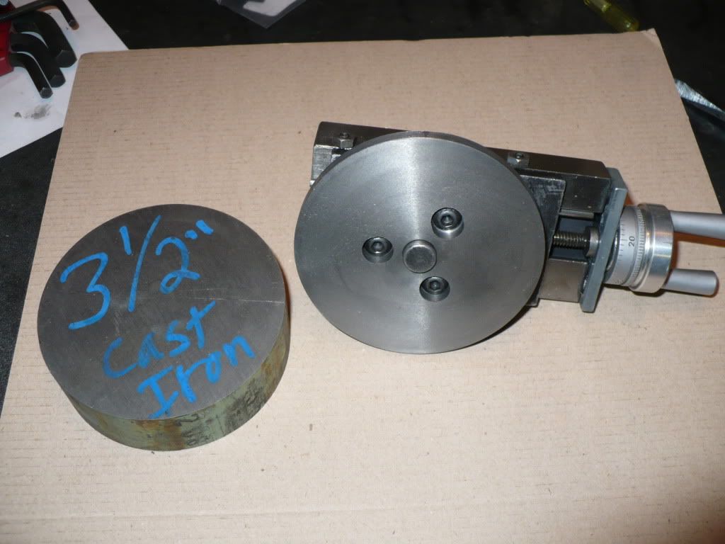
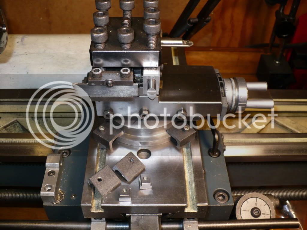
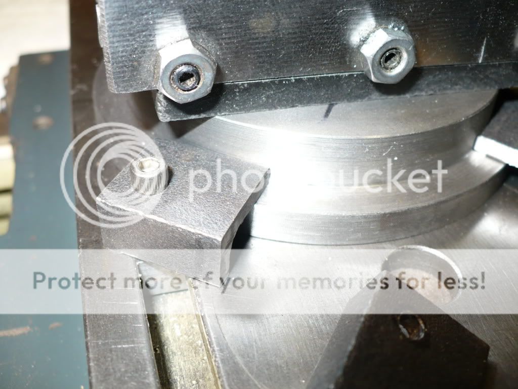
I have an early 1992 Enco brand 9 x 20 bench lathe. The lack of rigidity in the tool post makes cutting off a work piece difficult at best. I have seen the tool post bend over under load, jam the cut off tool, and stall the motor. In severe cases the cut off tool breaks, and/or the work piece is ripped out of the chuck. Its very frustrating to say the least. Tool chatter is another problem that can't be avoided on larger diameters such as flywheels.

I recently saw an improved four bolt tool post hold down plate on E-Bay that claims to solve the problem. Has any one tried this, or their own shop made version.
Is this a viable solution to the problem, or is replacing the entire unit with a quick change tool holder the only way to positively eliminate this problem.

http://cgi.ebay.com/A2Z-CNC-9x20-La...676?pt=LH_DefaultDomain_0&hash=item336212b2c4
 
IIRC rick posted that mod here . It seems to be a common first mod for the 9 x 20.
Tin
 
MB,
I made the Pitkin 4 bolt compound clamp for my Grizzly G4000. It made a huge difference. It's so effective someone went commercial and you can buy them at Little Machine Shop, eBay and other places. They're about $45 but also easy to make.

Cheers,
Phil
 
Thanks guys, with all of the information you posted, I have a good understanding of what needs to be done, and how to do it.

I lived with this problem far to long, and its high time that I deal with it once and for all.

-MB
 
I have been lurking here for more than a year (and enjoying the forum very much! :)), so I've decided it is high time I contributed something in return for all I get out of reading.
This particular subject is close to my heart, because I am also hoping to improve my lathe.
Mine already comes with "four bolt" design and although I am sure it is an improvement on the "two bolt" design, as far as I am concerned it is still pretty bad design :mad:.
Here is why I think so - starting with the crossection of topslide:

You need the "gap" where shown, so that you can trap and secure rotating part.
Now, guess what happens when you tighten those four bolts ;D

The gap between the two parts disappears, everything locks nicely ... only your topslide distorts and you actually end up with more play than you had before you started ;)
Of course you can be gentle with the spanner and tighten the bolts judiciously but ... whatever you do, you are distorting things!
Of course there are long established designs that address the problem. Here is one of them:

Three bolts apply now side load on the conical part of topslide, there is no gap to distort things when tightening four bolts (they are now only used to secure topslide to crossslide). The topslide is secured and locked with three wedges pushing against conical centre part.
I will be implementing this design to my lathe soon (right now SWMBO :bow: needs a new kitchen, so my lathe will have to wait :D)
In the meantime, maybe it will provide an inspiration for someone?

Chris
ps if I got it right - by clicking on the pics you should be able to get bigger ones.
 
Hi Bambuco and welcome To HMEM. The points you make are well taken. The flexing of the 'clamping ring' coupled with the small diameter of the graduated support base make up an assembly that is prone to a huge amount of flex. Fortunately their are simple solutions to this problem on the 9 x20 lathes. After looking at the options presented, I like the 'donut' design shown on the Yahoo groups link. Its a very simple solution that addresses the problem well, and the lathe can be converted back to original in a few minutes.

You make a good point about the flex in these designs, and easier to understand with the illustrations you provided.

EDIT: When I said I like the 'donut', I'm referring to "The Donut" designed by John Pitkin, and presented on the 9 x 20 lathe Yahoo group.

-MB
 
Thanks MB,
Indeed, the "donut" solution is simple and effective - I like it as well.
KISS ;D

Chris
 
bambuko said:
Thanks MB,
Indeed, the "donut" solution is simple and effective - I like it as well.
KISS ;D

Chris

Chris, with your understanding of the flex problem, I'm happy to hear that you also like "The Donut" desighn.

I need to make a material choice. My options are aluminum, cold rolled steel, or cast iron. Al seems like it might not be strong enough, CRS is harder to machine and will warp due to built in stresses, cast iron might be the best option.

The irony here is that you need the modification, to make the modification. Chatter city here I come! :big:

-MB

 
Well ...
"donut" design doesn't have tapers, so you do not need to set the topslide at an angle.
You can:
Take rectangle of metal (just rough sawn) of appropriate thickness, drill four holes to secure it to the crosslide and all the holes needed to secure topslide to the said rectangle (but without ability to rotate it).
You now have solid topslide with one less source of flex and weakness able to do any straight (not tapered) turning, and it only needs accurate drilling (providing the slab of metal has correct thickness).
This is rough and ready version of:
Radford's Improved Topslide for Myford Lathe

What do you reckon?

Chris
 
Chris, I agree with you. The shape of the base can be a square block. The shape is somewhat irrelevant to me. The round design allows the top slide to be rotated for offset turning, and I think that's why John Pitkin designed it that way. Either way both the top and bottom need to be machined parallel and to the exact height of my particular machine.

I'm starting to see that the tool post rigidity issue is not limited to the 9 x20 Asian copies of the original Emco desighn, based on the Myford link you provided.

The choice of metal is still on my mind. scratch.gif

-MB
 
Pat J said:
Welcome Chris-
Nice CAD work.
Pat J
thanks :) for the welcome
and as for the CAD ... it's nice to be able to present the idea clearly, but it doesn't really matter whether it's CAD or not - fag packet sketch will do just as well. It's the idea behind the sketch that matters. I was always amused at work, when I saw young kids who learned to use CAD - they all thought it made them into "designers" :bow:

Metal Butcher said:
...I'm starting to see that the tool post rigidity issue is not limited to the 9 x20 Asian copies of the original Emco desighn, based on the Myford link you provided...
-MB

They all are indeed vulnerable, but Myford is nowhere near as bad as Emco and it's many clones. Myford has T slots perpendicular to the way, meaning that at least between the slots you have full strength to the crosslide. Emco etc puts the two T slots parallel to the way making it weaker at the worst possible point ???
You couldn't design it worse if this was your cunning plan :p :big:

Chris
 
#1 With this update the needed improvement to my lathes tool post is complete. The metals order that included the cast iron disc needed for the project came in. I asked for the disc to be cut 3/4" thick. What I got was 1-1/8" thick. This made my problem a bigger problem. It is very difficult for me to machine discs of this size with the weak tool post on my lathe. This is the reason for this project in the first place. Its a classic case of you need one, to make one.

I spoke to George (gbritnell) about my concerns that also included a question as to the quality of the iron I received. George suggested I stop by and bring the piece of cast iron with me and the drawing of the part, saying he would like to take a few cuts and see how it machines.

Well, one cut lead to another, and before I new it all the major machining was done. George went at it like a programed CNC machine! I stood there like a motionless manaquine while belts were shifted, levers were moved, and tools were swithced faster than I could grasp what was taking place!

George, My sincerest Thank You for helping me out. It would have been a miserable job for me just takeing 5 or 10 thousands off at a time to reduce the thickness of the disc from 1-1/8" down to 5/8".

Below is a picture of an identical disc (I ordered two) used, and the finished 'donut' base for my tool post allready mounted on the bottom of the cross slide.

P1040997.jpg


#2 I drilled and counter bored the three clearance holes for the button head cap screws that hold the base to the cross slide. After measuring up the t-slots on my lathe, I machined up four nuts and tapped them 6-32. And the four hold down clamps were made from angle iron.

P1050003.jpg


#3 The majority of the credit for this lathe improvement project goes to George Britnell for doing the hard part of all the major machining. Very accurately too, I might add :bow: :bow:

The design credit goes to John Pitkin for "The Donut" compound mount. I consider it the only one worth making. :bow:

And I get no credit for standing around like a dummy, and for drilling a few holes. :-[


P1050005.jpg


-MB

 
MB - When you've had a chance to use it, especially on difficult cuts let us know how you like it.

Cheers,
Phil
 
This was the first job I did when modding my 9*20....
2nd up was a vfd... :)

Never looked back...
 
Philjoe5 said:
MB - When you've had a chance to use it, especially on difficult cuts let us know how you like it.

Cheers,
Phil

Hi Phil. I tried out the "The Donut" base today, and I can honestly say WOW! What a difference over the way it came from the factory! Its like I got an altogether different lathe. Now that I have "The Donut", I could make 'The Donut". :big:

To test it out, I faced both sides and the O.D. of an identical 3-1/2" x 1-1/8" cast iron disc used to make the new compound base. And I also faced one side of a 4" aluminum disc. There was absolutely zero chatter or harmonics during the cuts, and a close up examination of the reflective surfaces shows no distortions what so ever. Simply super!

With this set-up the compound and tool post is now rock-solid. What a great design! Not only does it work well, its also very simple to make with no real critical dimensions.

Its well worth spending $5 for a 3-1/2" x 1" piece of quality cast iron for the job. Bolt Depot or your local hardware store should have the metric button head bolts and the 3/4" angle iron.

http://www.speedymetals.com/pc-4287-8388-3-12-rd-gray-cast-iron-class-40.aspx

-MB


Glad that you are happy with it, Rick. It looks very serious and ready to work!
This will postpone a new lathe for you for some time, I suppose? ;)
 

Latest posts

Back
Top