3cc Diesel - My first ICE

Home Model Engine Machinist Forum

Help Support Home Model Engine Machinist Forum:

This site may earn a commission from merchant affiliate links, including eBay, Amazon, and others.
Fluffy Bunnies are Mrs M's department :big:
 
Hi All,

Friday turned into a fiasco, with wrong numbers on tanks being sent all over the world. Of course people couldn't find the bloody things they were looking for the wrong number ::) ::)

When that was finally put to bed, I called it a day so did not get too much done. Anyway it's POETS day isn't it?

Below is what I did manage to achieve.

Machining the main shaft of the crankshaft.

100_0533.jpg


Final cut on the main shaft.

100_0534.jpg


Ready to start lapping the main shaft to fit the crankcase nose.

100_0535.jpg


Lapping the shaft.

100_0536.jpg


Have a nice weekend everyone :D :D
 
hi there

I new to all this stuff of machining , but I would like to try to do this engine , can u give some plans???

thanks
 
Stegaster,

Plans available from:

http://www.ejwinter.com.au/

Plan No. IC9

If you are new to this hobby, I strongly recommend you make a simple steam engine 1st ;D
There are plenty of great examples elsewhere on the board.

And WELCOME to a great hobby and a great forum :)

Regards
Bob
 
i got the catalogue from them last week Bob,

best and worst $10 i ever spent

best cause theres so many good plans

worse i can see a lot of missing hours building them

i see you did not get the casting kit for that one but doing it "ala Scratche" :bow: :bow: :bow:

i ordered the No.2 mill engine castings yesterday ::) ;D

cheers

jack
 
Jack,

Purchased castings are: (Only my opinion :p) I'm sure others will disagree, but that's what makes the world go round.

1. Very expensive to buy.
2. It's more easy to stuff up the machining, due to marking out and clamping requirements.
3. Some are of poor quality and you don't know about it until you
(a) start to mark out
(b) start machining.
4. It's not as much fun as making a clothes peg from a telegraph pole. ::)

On the plus side.
An engine made from castings has the potential to look much more authentic than one blocked out of solid. Just look at the Chuck Fosters 3 cyl Fairbanks Morse. For me it would not have half the visual appeal and impact if it was blocked out.

Regards
Bob
 
Bob each to their own

but i have done rebores/rebuilds on Izuzu diesal motors and reworked Amal carbs :big: ( talk poor quality!!)

so am well trained in bodgies on cast items, maybe the only thing i'm "good" at

besides once i have them here i can copy to my hearts content ( another thing i'm ok at )

i can cast a few metals so will experiment once i get the paid work out the way
besides its a good place to start with what i have in mind for later on

ageed on the telegraph pole bit but the small stuff is a bit elusive for me yet ( look at my pile of practise bits and peices)

the plan is to do the mill then maybe the IC/11 from Mr Winter then maybe i'll have enough practise to start on what i want to build and that will be scratch built

but thanks again for the tips :bow:

cheers

jack


Start of another week - My how time flies when your having fun ::)

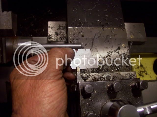
Today saw the main shaft of the crankshaft lapped and fitted to the crankcase and a start made on a jig for machining the big end.

One thing I have learned, is that brass laps are a dead loss :wall: I don't have a good techo reason why but I suspect it has something to do with the zinc content. The de-zinced brass bolt I used as a cylinder lap was fine, but the gudgeon pin was long winded and the main shaft went nowhere until I changed to a cast iron lap. :eek: ???

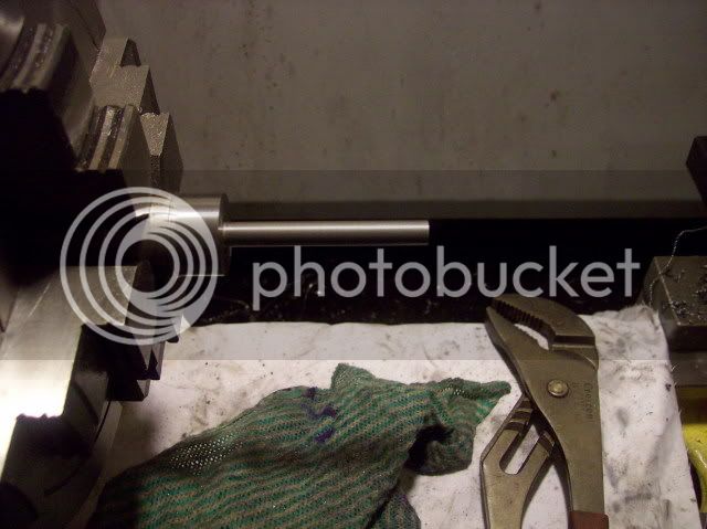
The surface finish after fine lapping paste, oil and a cast iron lap. (The multi grips area hang over from the brass lap and were used to pry apart my fingers ::).

100_0539.jpg


Almost there :eek: time to change to metal polish.

100_0542.jpg


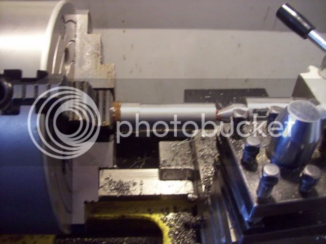
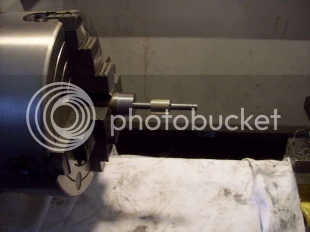
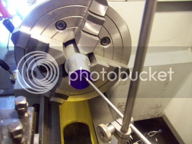
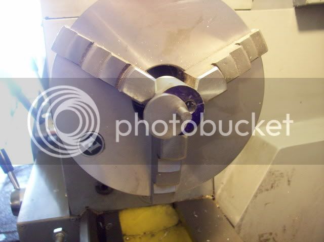
Thank goodness that's done ;D The crankshaft in the crankcase.

100_0544.jpg


100_0545.jpg


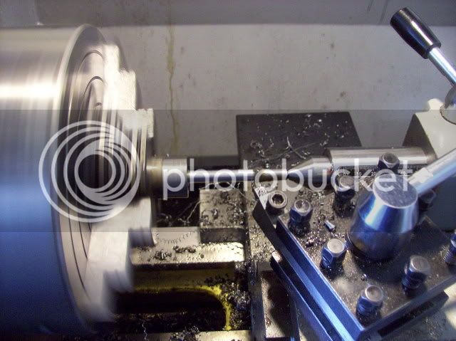
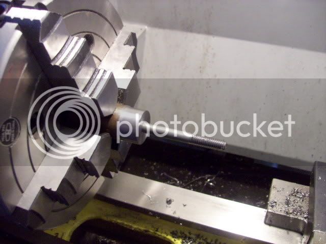
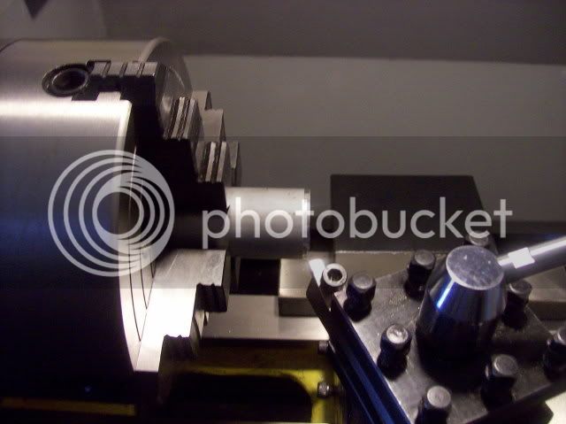
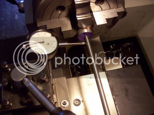
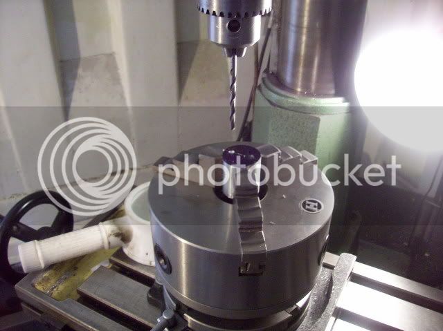
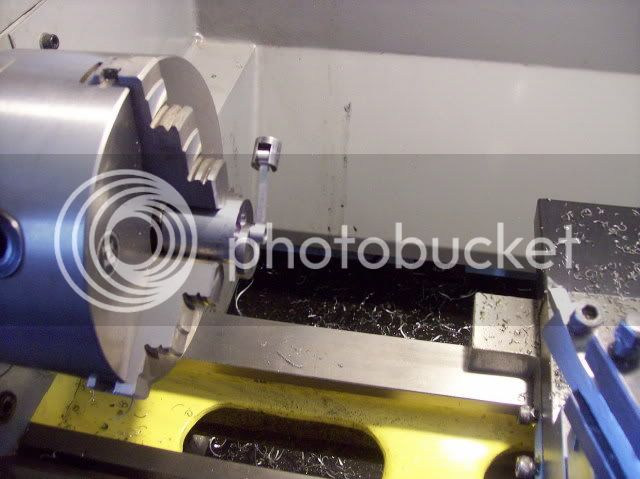
Setting up to cut the crankshaft thread.

100_0546.jpg


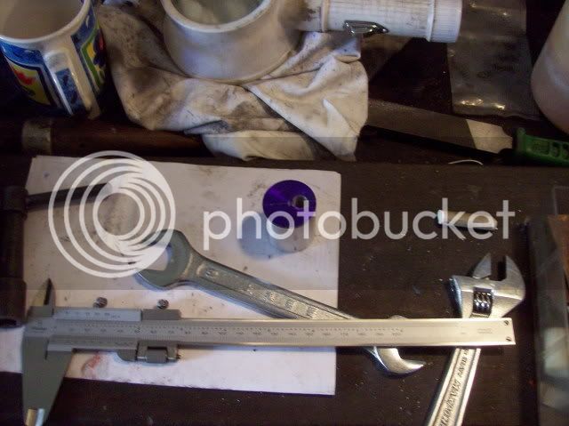
The completed thread.

100_0548.jpg


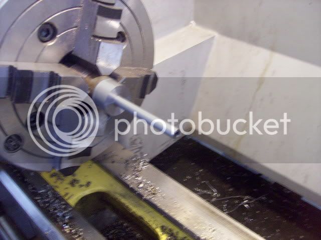
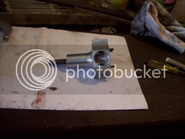
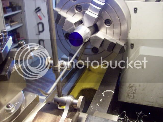
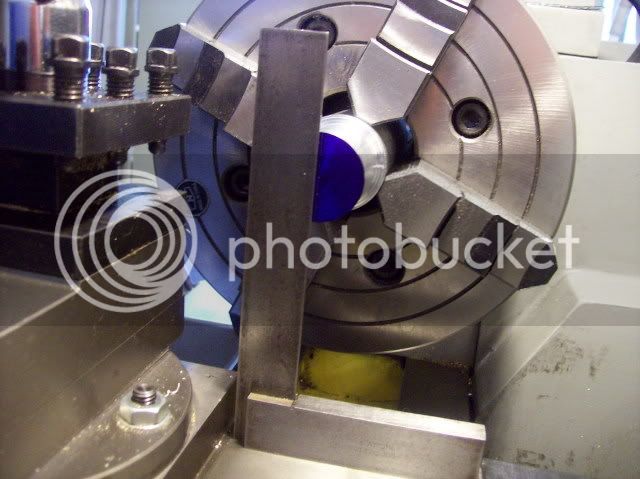
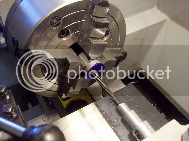
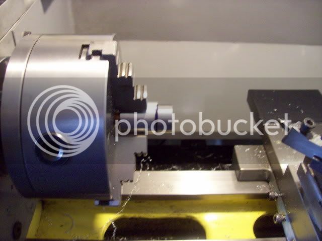
Test fit of crankshaft in the crankcase.

100_0549.jpg


100_0550.jpg


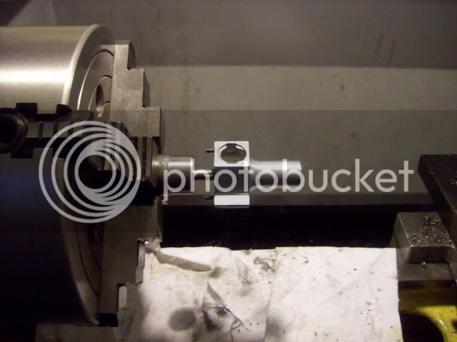
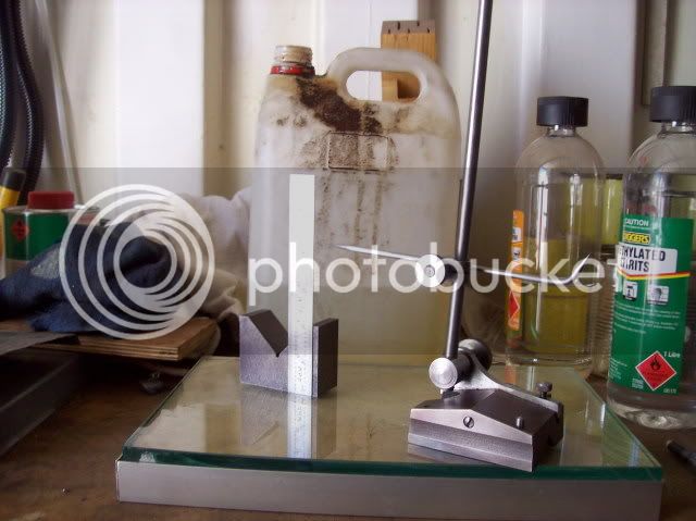
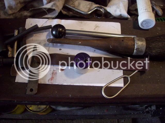
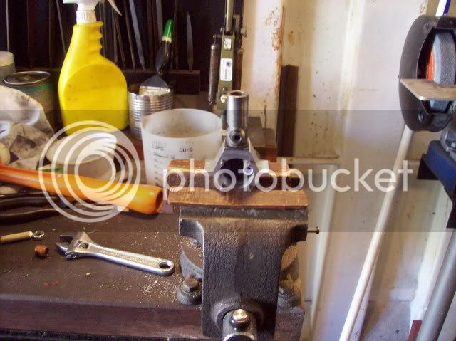
Aluminium for the crankshaft jig.

100_0551.jpg


Marking out the crankshaft jig for the crank throw offset.

100_0552.jpg


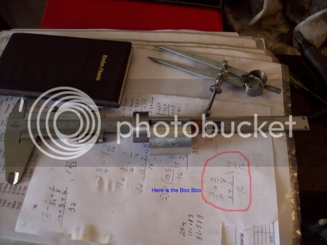
Transfer of centre height + 3/8"

100_0553.jpg


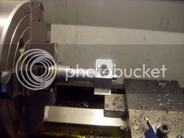
Lining up the jig for offset transfer.

100_0554.jpg


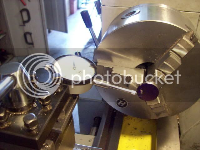
Marking off the centre point of the offset.

100_0555.jpg


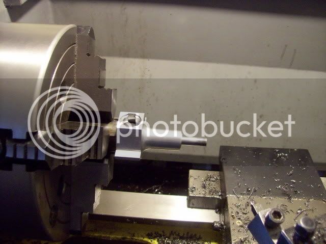
Setting up to the offset point.

100_0556.jpg


Reaming the jig to take the crankshaft.

100_0557.jpg


Called it a day at this point. Let's see what tomorrow brings
 
Hi Guys,

Well, so much for my marking off the offset :-[

Read on

On removing the jig to insert the crankshaft, it just didn't look right ??? ??? ???
Suffice to say my maths or should I say my arithmetic was up the proverbial creek without a paddle on measuring I was only out by 1/8" :eek: ::) :eek:

Here is the stuffed up jig.

100_0558.jpg


Set up in the mill this time to try and achieve correct positioning of the offset.

100_0559.jpg


The jig with the correct and incorrect offsets, note I marked the correct hole with a line to the crank OD.

100_0560.jpg


The crankshaft mounted in the jig.

100_0561A.jpg


Back in the lathe and ready to start machining the big end and thickness of the throw.

100_0562.jpg


Half way through the machining.

100_0563.jpg


The big end ready for lapping.

100_0565.jpg


Had an afternoon appointment and another one tomorrow morning so maybe Thursday ???
 
Bob,
Great photos and progress. Thanks for the update. I was happy to see the pics of drilling an offset on the lathe using the four jaw to hold the work. I had tried that once but my offset was too far and I had trouble with two of the jaws gripping the workpiece.

Cheers,
Phil
 
Another way to establish the eccentricity of the crankpin fixture is to use a DI to indicate directly off the outer surface of the fixture. Once the DI shows a deflection (up-and-down) twice the crankpin throw, you are there.

Drill and ream away.

George
 
Phil and George,

Thanks for your continued support and input, yet another way to skin the proverbial cat. :bow:

Phil, it is sometimes possible to use a split sleeve, increasing the OD of the part to be offset. Just depends on how much is left on the jaw thread to get the offset required. Alternatively a faceplate may be used to achieve the required offset in a lathe.

Best Regards
Bob :)
 
Bob, on my Crusader, I think that the crankshaft is the most difficult part to machine. The second would be the cylinder with the ports and such, but IMO the crankshaft takes the cake. Al of that said, your crank came out looking great! Your little engine is coming along very nicely.

Keep up the great work!
 
W/E,

Thanks for your continued support and input.

Best Regards
Bob ;)
 
I was interested to see how you machined the crankpin as I struggled to say the least with that on my hot air engine.

Once you have drilled the offset, how do you set that to run true? Just put the crankshaft in it and set that to run true with the dti? Your method of drilling in the milling machine seems far easier and more repeatable to me.

I struggle to set a point running true in the lathe 4 jaw ... how do you do that? I noticed you had some sort of centre? Was that floating with a dti on that?

Keep up the good work.

Thanks,

NIck
 
Nick,

Thanks for your continued interest. :bow:

To try and answer your questions :p

The offset in the jig is made relative to the jig centre and I am relying on the 3 jaw being true enough to locate the jig within acceptable limits. I'm lucky that my 3 jaw has minimal runout. If you have an older stressed 3 jaw, or one which has been abused then you would have to set up the jig OD to run true in the 4 jaw using a DTI. ;D

The little gizmo shown with the DTI is a spring loaded centre finder. It's about 6" long 3/8" dia and on the tailstock end has a sliding fit female centre working against a fairly lightly loaded spring. To set up locate between the centres and adjust the tailstock to compress the spring about half way. Then measure way. It's a good idea to try and get somewhere near by eye before using the finder as it does not like large angles of offset. :D

Hope this helps ??? ???

Regards
Bob
 
Well, achieved a little lot less than I should have ::)

Somehow, (one of my Asian friends), I managed to engage the X feed and sheared the lead screw shear pin :eek: :eek:
No damage to the lathe but my ego took a bashing :-[ :'( :-[ :'( so instead of progress I spent some time replacing the shear pin. ;D

Almost finished lapping.

100_0568.jpg


The completed crank pin.

100_0570.jpg


A trial assembly of the bits made so far. Spent some time filing the conrod to clear the crankcase near the top of the stroke - should have been more careful 1st time around :p

100_0571.jpg


Setting the crank pin horizontal to mark out the centre, allowing machining of the crank arm for balance.

100_0572.jpg


Hopefully tomorrow will see the crankshaft in the mill ???
 
Thanks Nick and Eric for your support. :D

Regards
Bob
 

Latest posts

Back
Top