3cc Diesel - My first ICE

Home Model Engine Machinist Forum

Help Support Home Model Engine Machinist Forum:

This site may earn a commission from merchant affiliate links, including eBay, Amazon, and others.

Maryak

Well-Known Member
Joined
Sep 12, 2008
Messages
4,990
Reaction score
77
Hi all,

I thought I would give record keeping a try as I progress with my current model. Promised myself I would do this with model 1, but failed dismally. This time your feedback and input into the project should, (I hope), keep me on my toes!

Today was a major swarf making day with Aluminium from A@*e-h@*e to breakfast, (sorry for the spelling for those of you who escaped King Georges clutches), as I started on the crankcase. I must admit - this is crankcase 2 as crankcase 1 went in the bin after I realised my math was up the proverbial creek at a point not to far before where I am now.

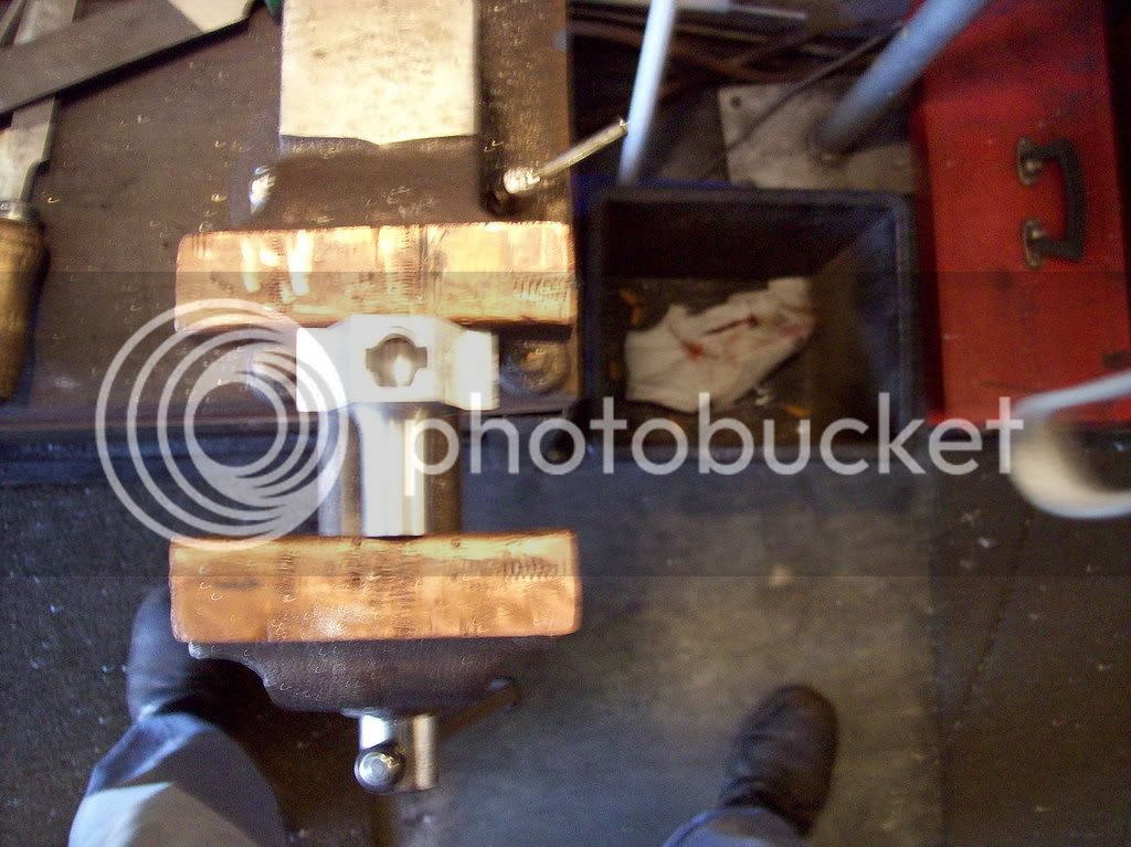
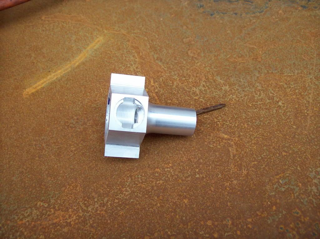
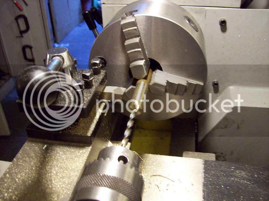
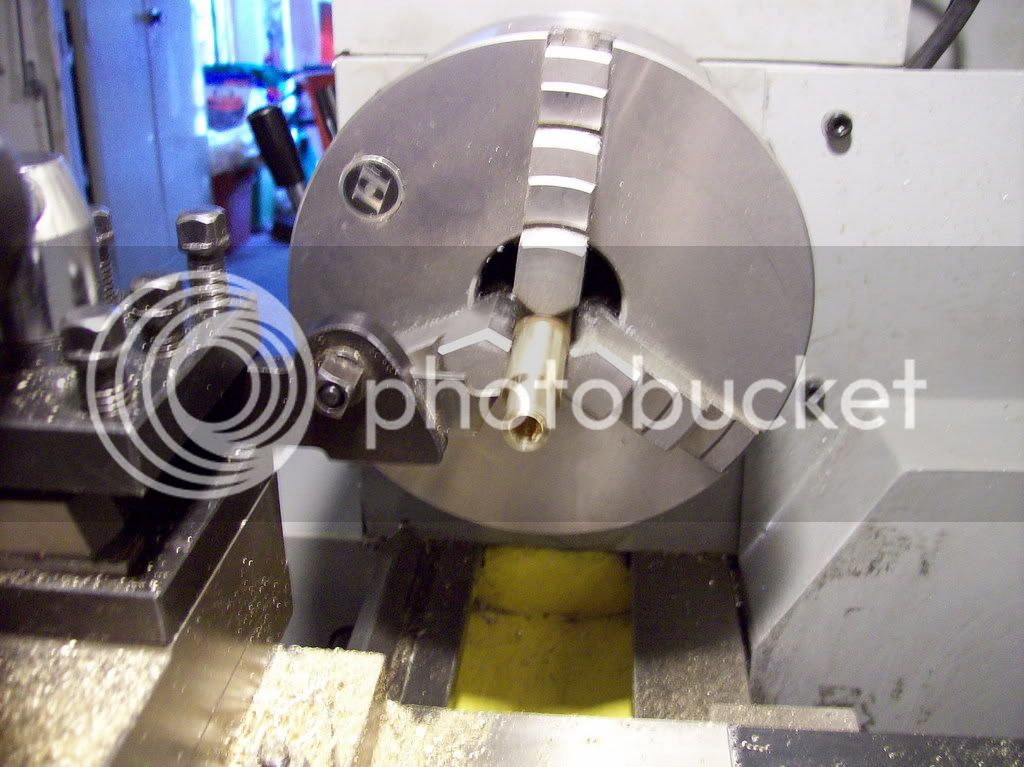
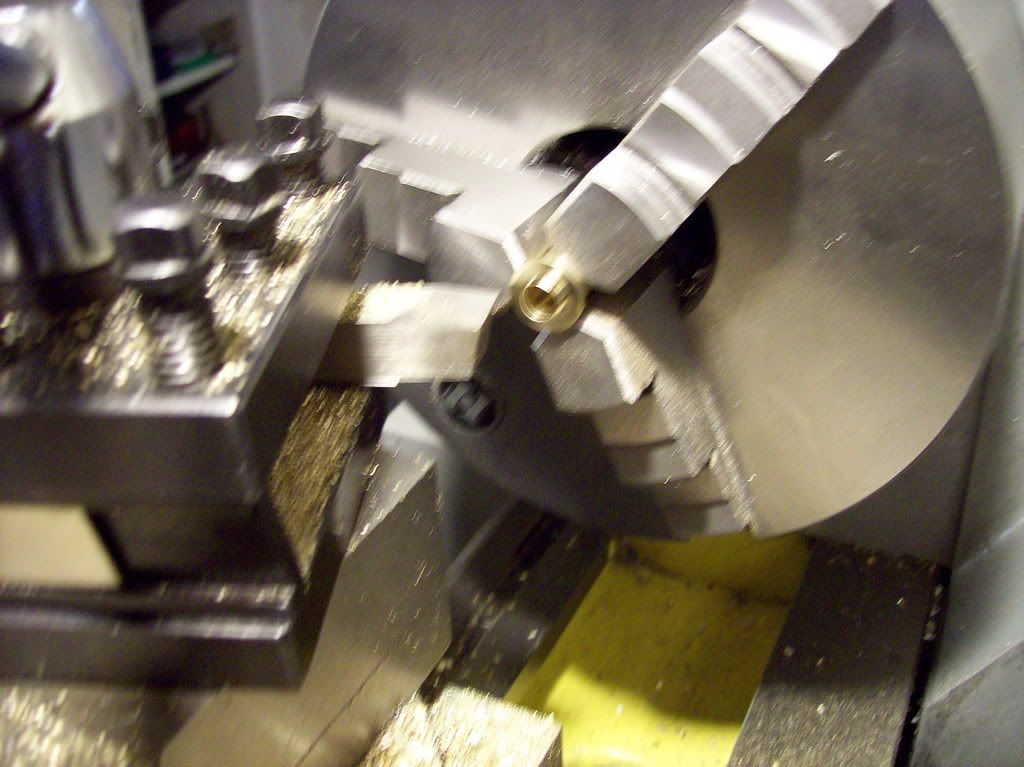
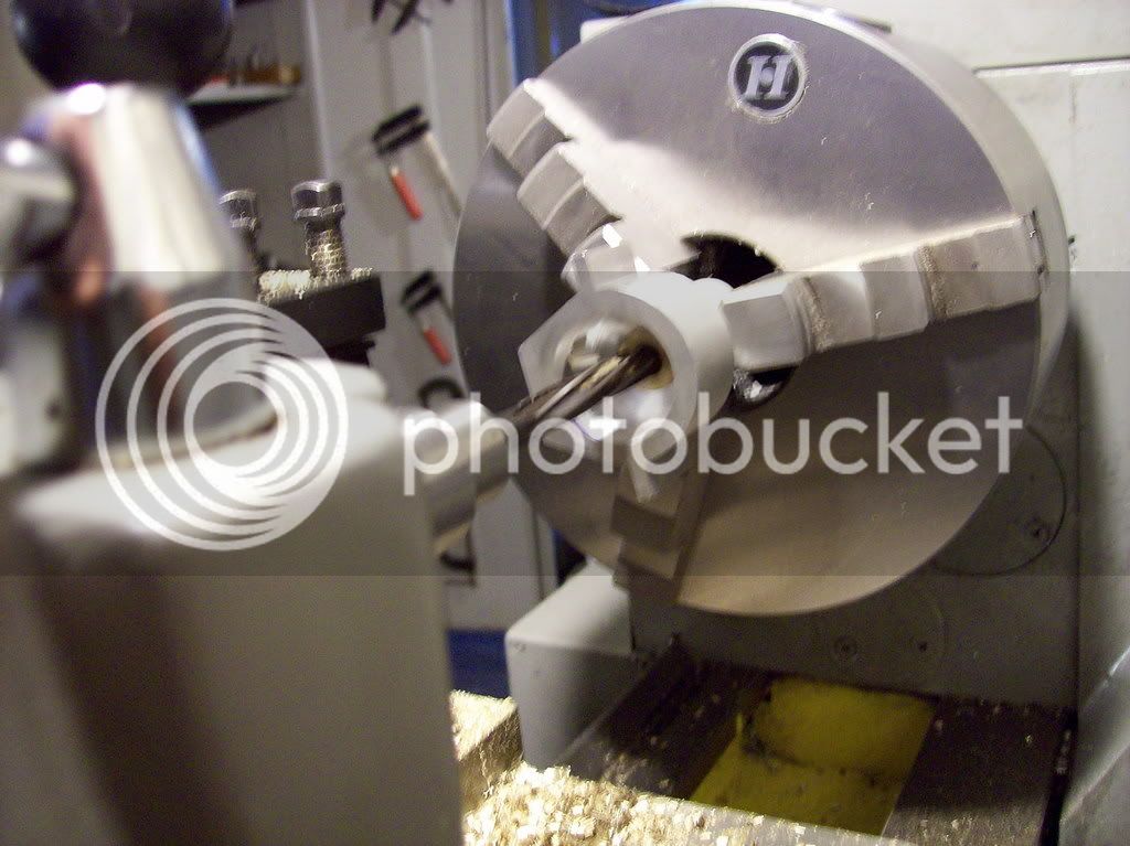
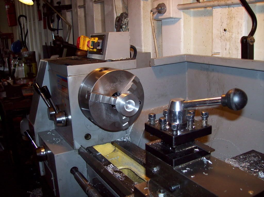
The first image is of the crankcase after the initial lathe work is complete and ready for transfer to the mill.

100_0312.jpg


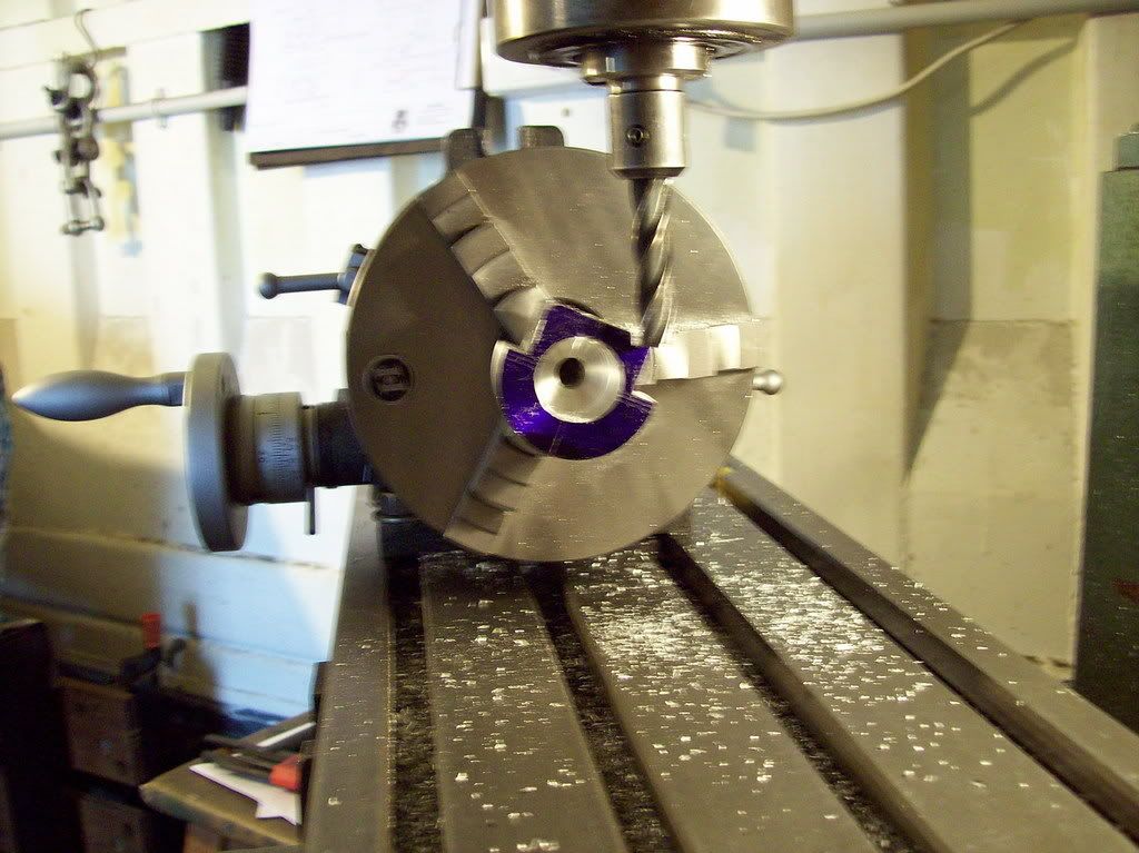
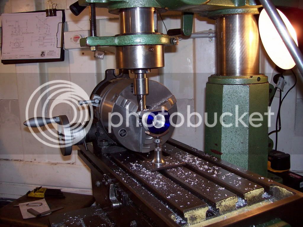
Next is the crankcase in the rotary table ready to mill the flat on which the cylinder sits
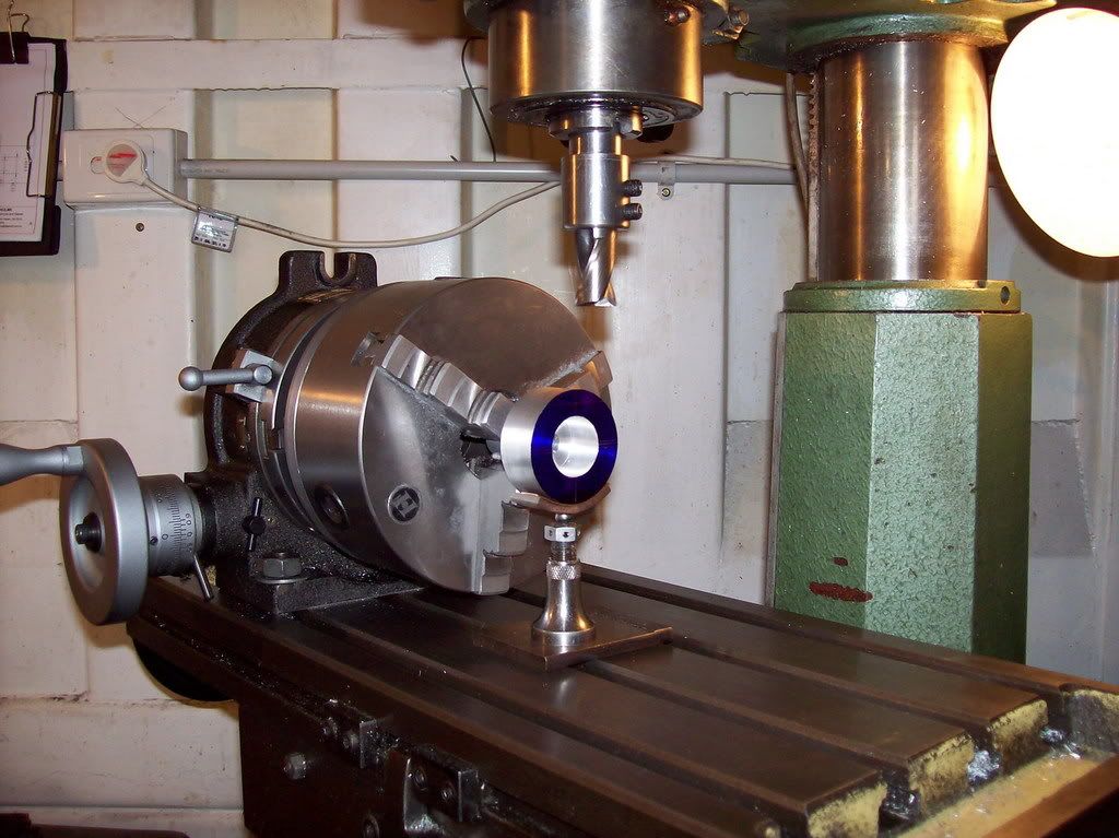
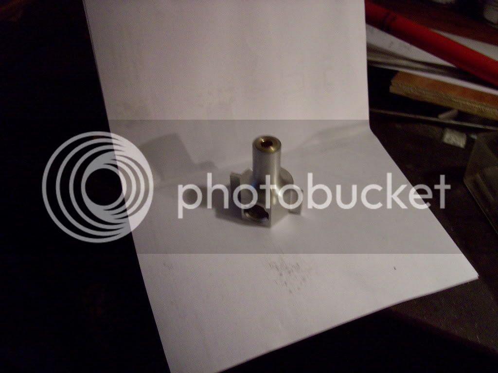
100_0313.jpg


The flat is milled

100_0314.jpg


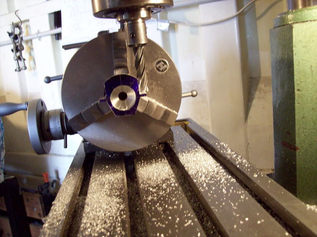
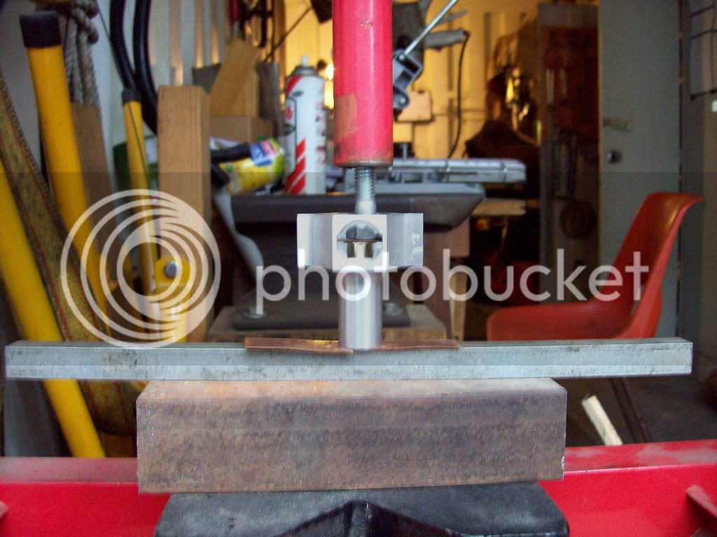
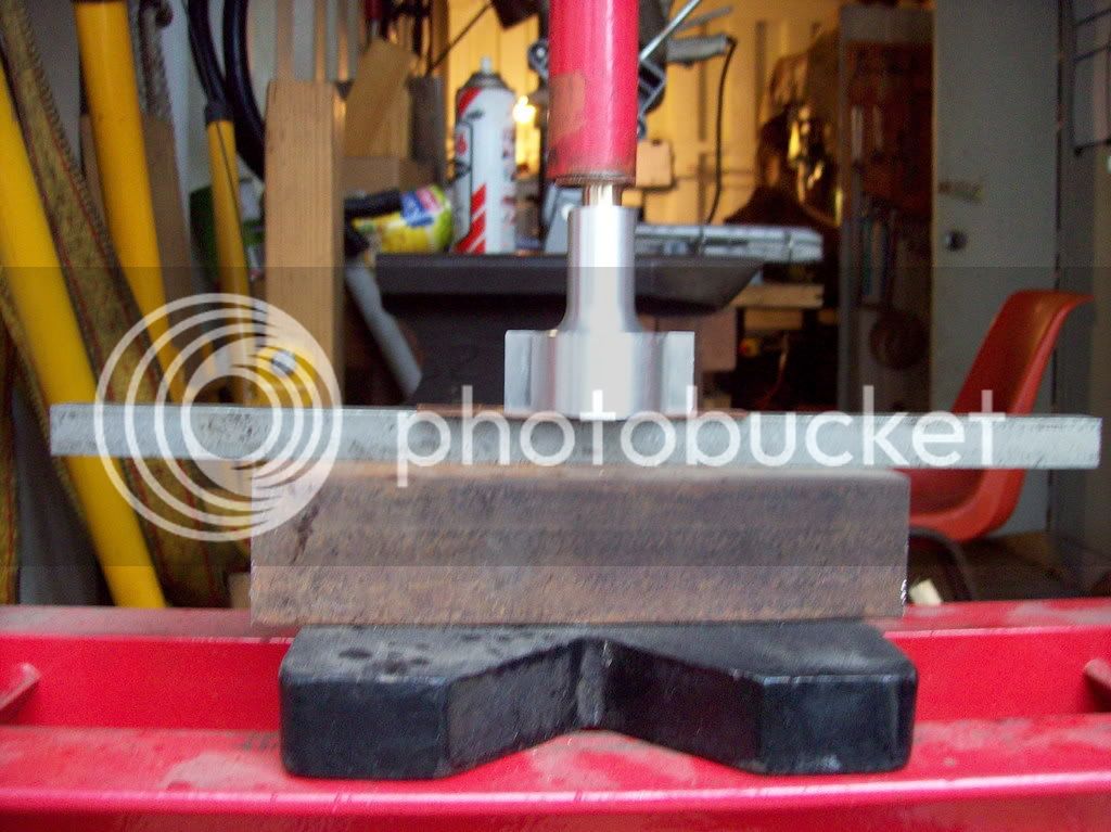
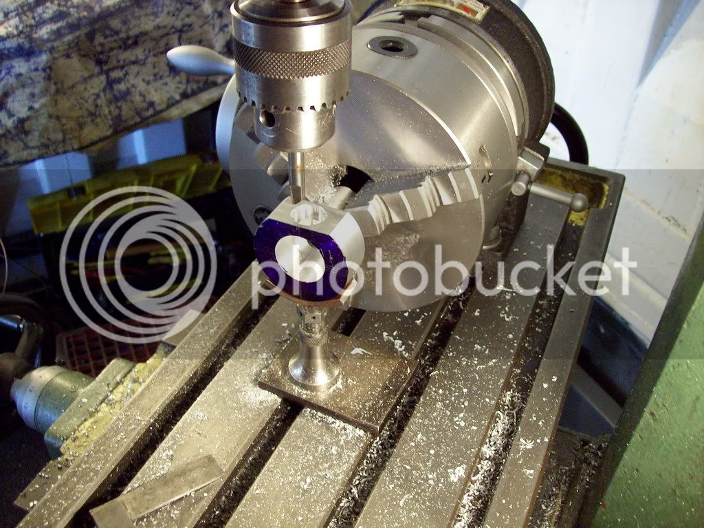
Slotting the clearance slots for the conrod.

100_0315.jpg


Having finished the slots it was time to call it a day. Tomorrow I hope to profile the outside of the crankcase and if that is successful its on to the cylinder if not its back to the scrap yard for more Alu!

Please feel free to offer comments, suggestions, criticisms etc. I will not be offended. Because as with the saddle stop - old dogs can learn new tricks.

 
Bern,

Thanks for your input

Alas today I did not seem to have as much success with the close up shots as yesterday, same camera, same operator, hopefully will be better next week. :p
 
Crankcase - Day 2

Profiling the angular sides.

100_0316.jpg


Profiling the round underbody.

100_0318.jpg


Phew :D finished the machining of the body - now to make the bearing bushes but that's for next week.

100_0320.jpg


This design seems to be very fiddly both with the crankcase and the cylinder, be that as it may it is interesting and challenging. It's not a design where your concentration can afford to lapse as the bigger most expensive bits both in size and time invested in them are the most complicated - well that's what I think so far.
 
Maryak,

It is looking great! Keep up the good work!

You are working on what I think is the most critical part of the engine, and that is the crankcase. The reason I believe the crankcase is the most critical?? It is the foundation of the engine, and if things are not true or slightly off, then the engine will not perform well or even at all. I'm not saying that the other parts are of no importance and that their tolerances are forgiving. Just everything is based on the crankcase.

Question: The snout on your CC is pretty beefy... Are you planning some fun with that or is it the way you are building the engine?

Looking forward to seeing more!!! Watching an engine being built is an inspiration to all, and especially to me as it is very similar to my current project. Seeing your post is really making me want to blow off my day's work and work on bits in the shop for the day!
 
I'd say you need to get away from the caffeine. :big:

Pics aren't to bad to see what your doing. Just keep up the good work. Like W/E said it's an inspiration.

Bernd
 
WarEagle,

The original design used a casting for the CC which is ribbed but has a solid core dia of some 5/8".

The bore of the CC is 7/16" fitted with bushes, as designed one is plain and the one inside the chamber is shouldered out to 9/16" to take up axial movement behind the crankshaft web.

I didn't much like the idea of steel on aluminium at the front of the engine so settled on 11/16" OD for the snout, a repeat of the inner bush for the rear giving a 9/16" bearing face for the steel bits which hold on the prop.

Just a thought but are the nut and spline washer steel?

The original drawing shows a combined pulley and flywheel??? so maybe it was designed for a boat. No idea of the material

If I need to reduce the size of the snout I can. :eek:
 
Bernd,

Thanks for your continued input.

After my morning heart starter, (coffee and a fag), I drink tea or water for the rest of the day. Returning home it's cognac and coke, (purely for medicinal purposes of course). ;)
 
Maryak said:
WarEagle,

The original design used a casting for the CC which is ribbed but has a solid core dia of some 5/8".

The bore of the CC is 7/16" fitted with bushes, as designed one is plain and the one inside the chamber is shouldered out to 9/16" to take up axial movement behind the crankshaft web.

I didn't much like the idea of steel on aluminium at the front of the engine so settled on 11/16" OD for the snout, a repeat of the inner bush for the rear giving a 9/16" bearing face for the steel bits which hold on the prop.

Just a thought but are the nut and spline washer steel?

The original drawing shows a combined pulley and flywheel??? so maybe it was designed for a boat. No idea of the material

If I need to reduce the size of the snout I can. :eek:

Well, there really isn't a need to reduce the snout diameter if you don't want to. The reason I had asked is were were talking about different ways of building the two Crusaders. One of the things we had considered was to fin the snout parallel to the crank shaft, but we scrapped that idea to save time.

Are you going to use a flywheel on your engine?

There is a stud from the crankshaft through the prop with a nut that does double duty as a spinner. The crankshaft is steel, the stud is steel, and the nut/spinner is aluminum in the Crusader design. There is also a plate the the prop is sandwiched against that mounts on the crank shaft. In the design we have, there is a .125" shear pin that keeps the prop turning.

The bushing in the Crusader has a significant smaller thrust area than your example. The crank shaft diameter on the Crusader is .500", and it is a press fit into a .625" hole (the snout). The thrust surface is a shoulder at the end of the bushing and if I recall correctly, the diameter of that shoulder is .675". This is as designed by the author of the HSM article. Note: This is not to say that one way is better than the other! Just comparing the designs of the two engines.

I am anxious to see your creation come to life!

 
WarEagle,

Not only do no fins make it easier to machine the lack of same make it much easier to hold and set up.

Today I had to transport SWMBO to the city and nearby was a model shop claiming all sorts of things about model aircraft, small engine powered cars etc., i.e. a big boys toy shop. Went in, waited a good 10 mins for the guy trying to sell some $1000 dune buggy radio controlled gizmo when finally he looked at me and asked could he help. I said could you please tell me the size prop I need for a 3cc engine, a whole $6-$16 looking in the displays. Looked me up and down thought for a whole 30 secs and said, "Sorry mate haven't a clue!

So that combined with, "Win of the Week," a nice solid piece of rolled brass prompts me to answer yes I reckon I might go for the flywheel and pulley combo.

Thanks for the info re bushes nuts spinners etc. The 3cc Crankshaft dia is 5/16" and the flywheel and pulley combo is 1-1/2" dia and 3/4" axial length.
 
Maryak,

You might find the information you are looking for on prop sizing right here. I have come to determine that if one is in the market for something slightly out of the ordinary, you have to know what you need before you go. Customer service for the most part has become extinct!

I do agree about the fin issue, and that among other things would be the reason it was decided to fore-go the snout fins. Really, unless the snout is too thin, it is nothing more than a cosmetic issue anyway.

W/E
 
Can't really comment on the prop or snout... but, I will say this: it is off to a good start!

Eric
 
Eric,

Thanks for the encouraging comment

Bob :)
 
War Eagle,

Slow learner, took me a while to figure right here was a link went there and it says 9x4.

Is that 9" dia and 4" pitch.?

Thanks for your patience
 
Maryak said:
War Eagle,

Slow learner, took me a while to figure right here was a link went there and it says 9x4.

Is that 9" dia and 4" pitch.?

Thanks for your patience

My apologies on the link. I should have made it a little more clear, or just posted the URL.

The first dimension is the prop diameter, and the second is the pitch. I am 95% sure that the measurements on that link are imperial, though it doesn't say for sure.

You are very welcome!
 
WarEagle,

Think I'll make a template saying thanks War Eagle, save me a hell of a lot of typing.

Bob :) :) :) :)
 
Maryak said:
WarEagle,

Think I'll make a template saying thanks War Eagle, save me a hell of a lot of typing.

Bob :) :) :) :)

LOL!!! :big:

Bob, no need to. That is what this place is about, and right now I am neck deep into a project very similar to yours, so I am easily able to point you in the right a direction that will help keep you going. Many others here have helped me out, and I am just paying it forward. One day, it may be you helping me out through something, or maybe you will be mentoring a newbie machinist!

That's what makes these forums such a great resource. It's like having a shop full of veteran machinists (and other talents, too) standing over your shoulder giving you advice on the problems you face and methods you use. And which one of us wouldn't benefit from that?!?!?!
 
Hi All,

Apart from the weather, which was lousy, (right when I needed both doors open), I think I had a reasonably successful morning in the shop. Cleaned up the crankcase and made and fitted the crankshaft bearing bushes.

The crankcase ready for bushing.

100_0322.jpg


Drilling the bushes after machining the major dia.

100_0324.jpg


Parting off the first bush after machining the minor dia and shoulder.

100_0325.jpg


Squaring and sizing the thrust face.

100_0326.jpg


The bushes ready for pressing into the crankcase - Force fit 0.001"

100_0327.jpg


Pressing the back bush into the crank chamber.

100_0328.jpg


Pressing the front bush into the crank snout.

100_0329.jpg


Reaming the bushes after pressing to try to attain best alignment.

100_0330.jpg


Crankcase with bushes in place and to size.

100_0331.jpg


So far so good. Next will be the end cover for the crankcase.
 
Really nice work Bob :bow: ............ how far undersized was the minor diameter ....ie, .... much did you leave to ream out

Looking forward to your progress.

CC ........... aka Dave ;)
 
Dave AKA Crewcab,

Thanks for your kind words.

The finished ID is 5/16" so I drilled the bushes to 19/64", (closest undersize drill I have), before pressing them in, so the reamer has to remove 0.016" off the diameter.

Bob :)
 
Back
Top