2CYL4STROKE
Active Member
- Joined
- Dec 7, 2009
- Messages
- 42
- Reaction score
- 0
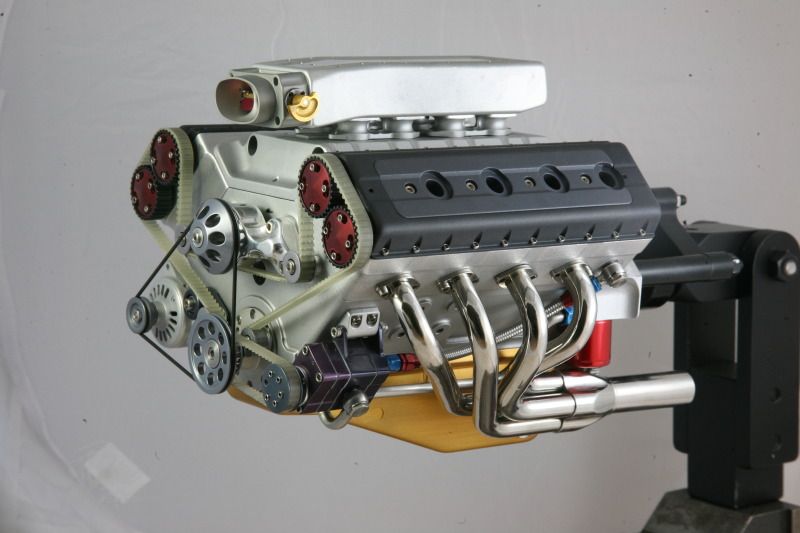
This is so beautiful piece of art 


 , I've done a little machine work with a Bridgeport and it is astonishing to see such intricate work being done on a non-CNC machine. Truly amazing!
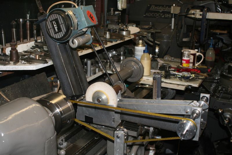
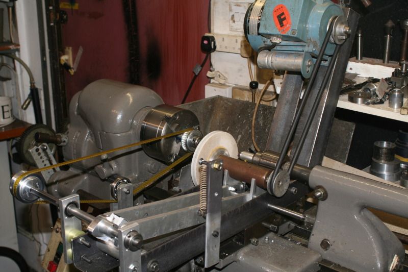
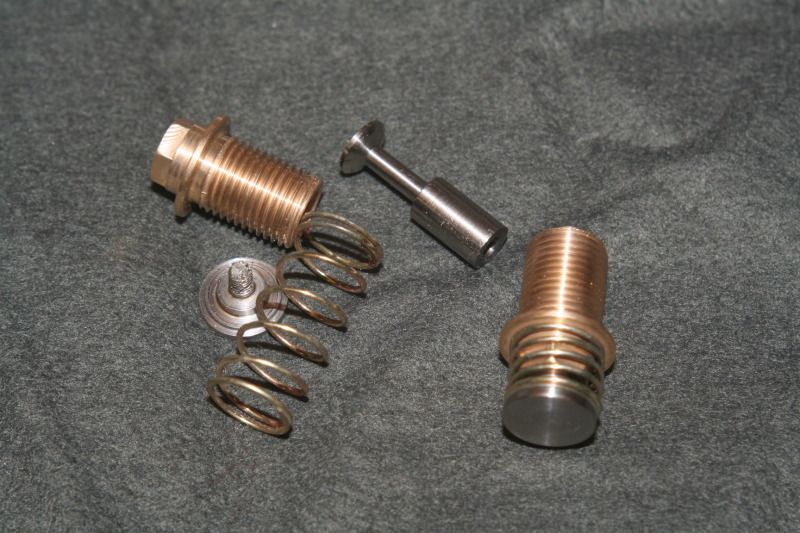
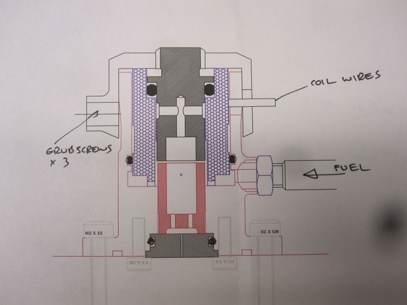
LongRat said:Yes, I love that valve idea. When you say you made a full-size cam lobe, how exactly did you do that? Normally when people make these scale reducing copy grinders they use a commercial cam to copy.
Enter your email address to join: