Rupnow Ovehead Cam Air Cooled

Home Model Engine Machinist Forum

Help Support Home Model Engine Machinist Forum:

This site may earn a commission from merchant affiliate links, including eBay, Amazon, and others.
Brian, Of course I enjoy it. I understand the need for a rest: Have at it!

I also hope to see a future build of something from you: They are all fun to follow and quite instructional. Rest now, but I think your brain might start itching with a new idea later.

Best of luck.

--ShopShoe
 
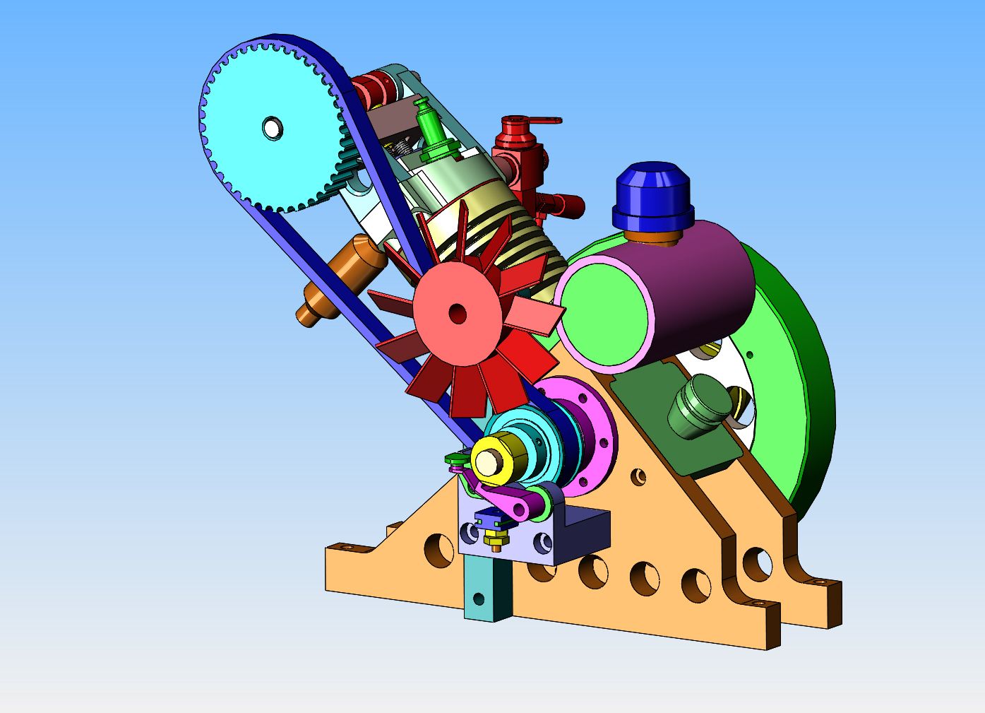
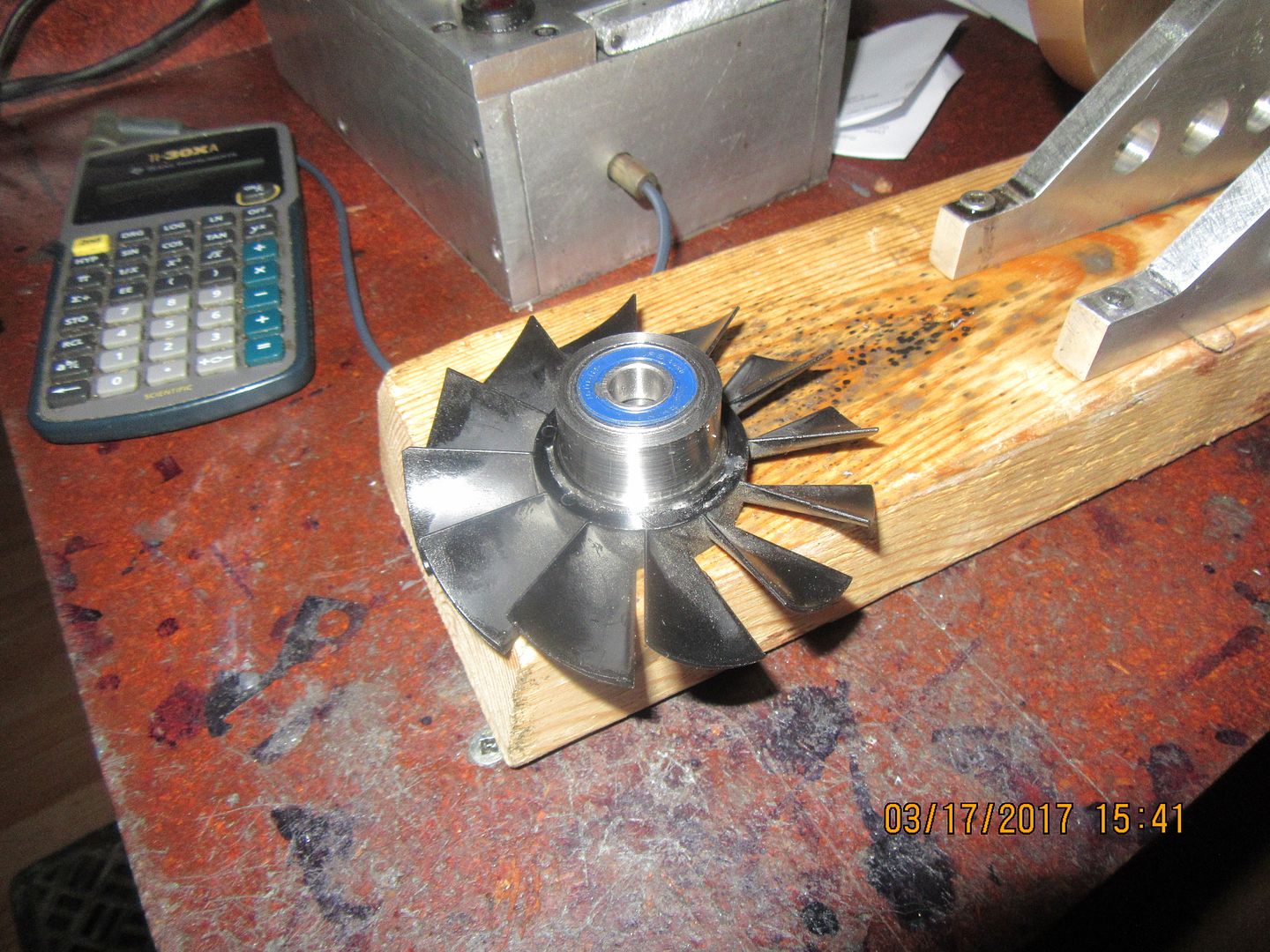
Today I'm at home for the first time in a week, as I've hit a temporary roadblock in the development of a spinforming lathe for a customer in Barrie. That's just fine, because I have a little project I want to take care of. The overhead cam engine works fine, but like all air cooled engines, it starts to suffer after about 15 minutes continuous running with no air movement to carry heat away from the cooling fins on the cylinder. I just happen to have a plastic fan 3 1/2" in diameter that I have rescued from something, but the pitch is wrong for my motor. However, the belt tensioner bearing revolves opposite to the crank and camshaft on that side of the engine, and is in a location where the fan would do the most good in terms of directing air flow over the cylinder. Todays exercise will be to find a way to attach the fan to the tensioner bearing so as to provide some cooling for the cylinder.
 
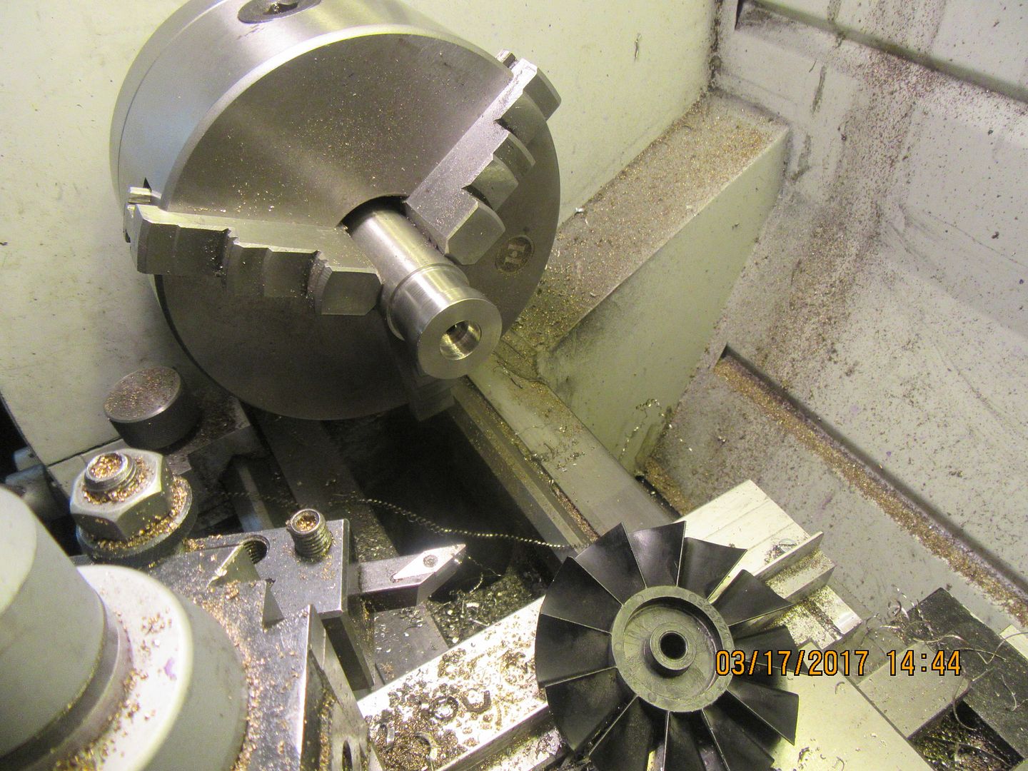
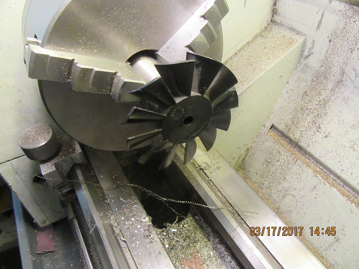
So, here's the way it goes---I've had a 1 1/4" diameter length of round 316 stainless kicking around my shop ever since I built the Kerzel about a century ago. First step was to profile the end of it to fit into the recess in the back of the plastic fan. Second thing to do was try the fan on for fit before I tore down my set-up.

 
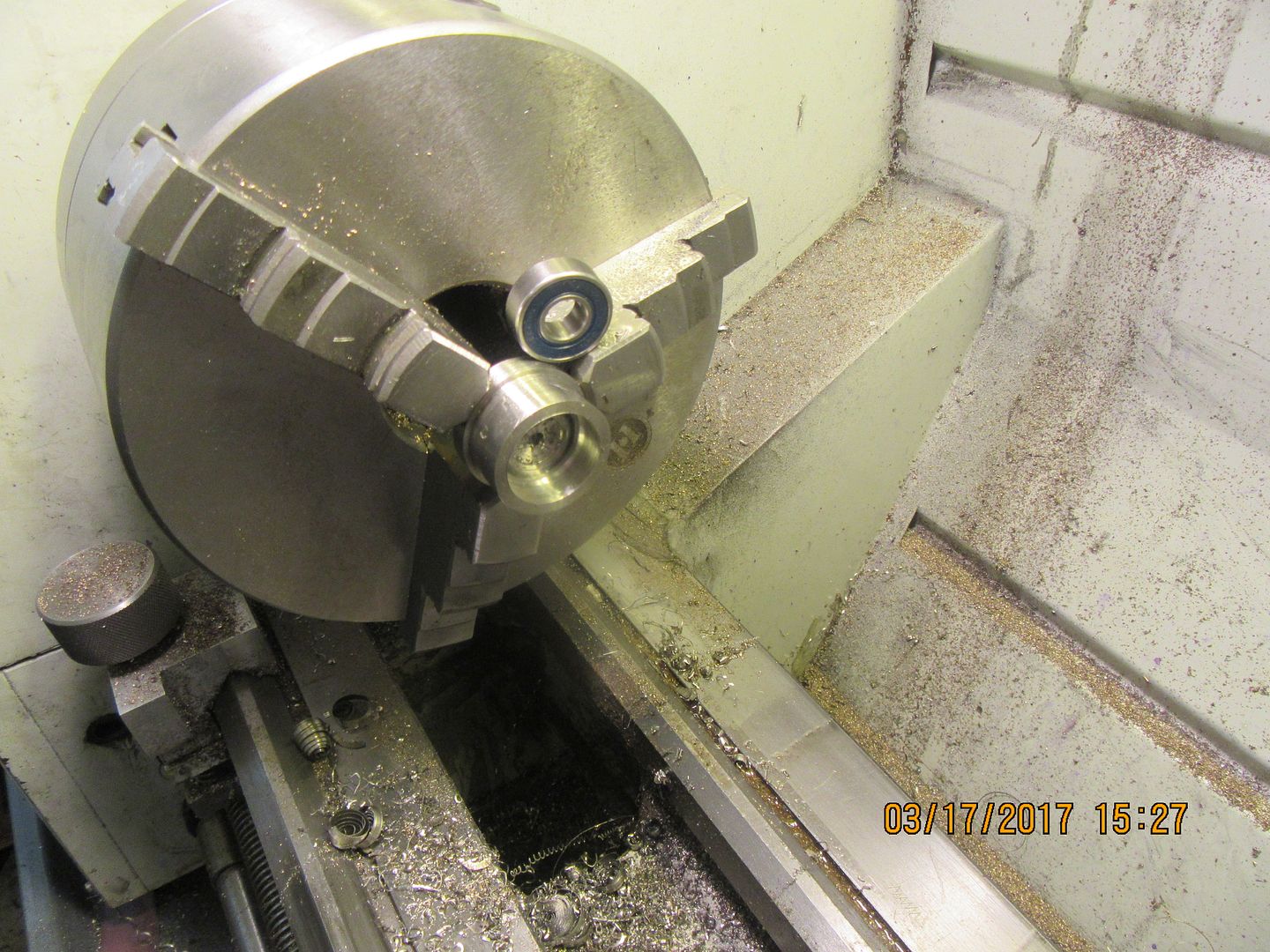
Third thing to do was part off the required length (I love parting off under power feed but it scares me right to death.), flip the part around and counterbore the other side for the bearing--very light press fit. Fourth thing to do was use 638 Loctite on the bearing side and two part epoxy on the fan side, and put everything together.

 
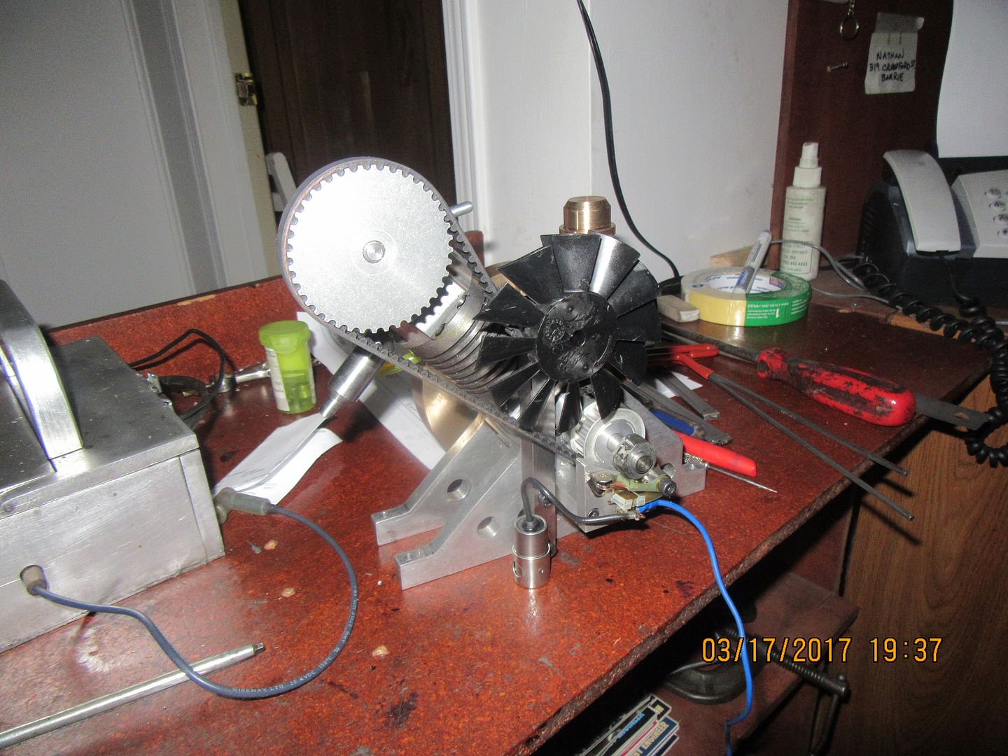
Now comes the tricky part---Taking the old belt tensioner bearing off and putting the new bearing/fan/adapter hub in place without letting the belt go slack and jump a tooth on either pulley. This would of course throw the valve timing out of whack, and I got so lucky with the very first time I set it up that I don't want to have to do it again.
 
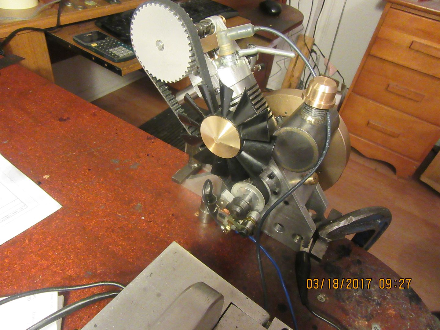
And here we have a rather nasty picture of the finished installation. Black never shows up very well in these digital photos using a flash. Tomorrow I will machine a cool little divot to plug the hole in the center of the fan and try to get a video up. everything works slick when turned by hand.
 
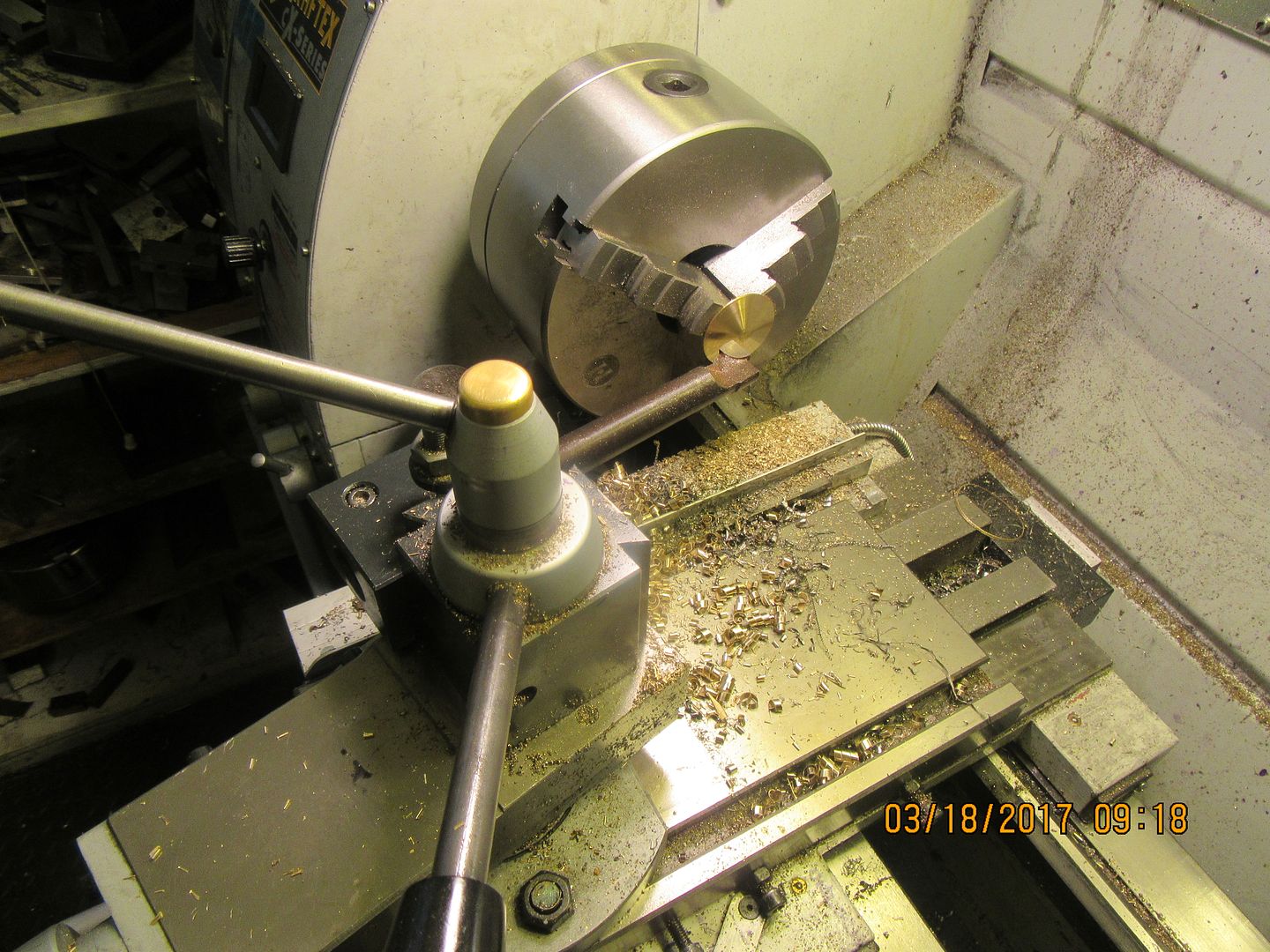
I follow the machining forums a lot, and one of the things I take note of is the weird and wonderful set-ups that people use to cut unconventional shapes with their lathes. The brass "dress-up" part on the face of the fan required a set-up that I have never attempted before. As you can see in the picture, it's not just a disc of brass. Rather, it is a shallow cone, like the old Dodge Lancer wheel-discs. There is a 0.300" diameter "spigot" on one side which fits into the hole in the center of the fan. I turned it first, then parted off the 1.5" diameter brass to about 3/16" thick. I flipped the part around in the chuck, then with the lathe running in reverse I used my longest carbide tipped boring tool to reach out and machine the disc from the center outward towards the back of the lathe in successive passes using the top-slide manual advance handle until I had a nice shallow cone formed. I am very impressed how well that method worked. I have epoxied the .300 diameter "spigot" into the hole in the center of the fan, and I think it looks quite "dashing". I will let the epoxy set up for an hour, and then put up a video. I have test ran the engine with the fan in place before I committed myself by epoxying the brass cap in place, and the fan puts out a very respectable breeze.

 
That brass cap really dresses up the fan. I like this one even more, now.

I've only ever made a shape like the brass cap myself by accident and by problems with my lathe. Now I gotta try it on purpose. Thanks for posting this refinement.

--ShopShoe
 
I have recently had a request for a set of the plans for this engine from a gentleman in USA, so have been busy as a Boxing day Beaver this morning converting all of my Solidworks files to .pdf files. In my opinion this is one of my more interesting engines, and as you have seen by the posted video, it is a great performer. If you wish to buy a set of the plans to build this engine, I charge $25.00 Canadian funds for the plans, all saved as pdf files.---Brian
 
A gentleman in South Dakota just finished this engine, based on the plans I sent to him. He discovered a few tweaks that were required to the drawings, but he has a runner, and it looks really good. I have updated the drawings to reflect any changes that were required. So--now there are two of these engines in the world. Mine and Jacks. I think this is one of the prettier engines I have designed.---Brian
 
A gentleman in South Dakota just finished this engine, based on the plans I sent to him. He discovered a few tweaks that were required to the drawings, but he has a runner, and it looks really good. I have updated the drawings to reflect any changes that were required. So--now there are two of these engines in the world. Mine and Jacks. I think this is one of the prettier engines I have designed.---Brian

And a video of it running.


https://youtu.be/OC3Udla2sIE
 
Back
Top