1/4 scale V8, first project.

Home Model Engine Machinist Forum

Help Support Home Model Engine Machinist Forum:

This site may earn a commission from merchant affiliate links, including eBay, Amazon, and others.
Well, nothing to report really. I got a bit bored with it after finishing those inlet pipes. they were the hardest things I've ever made, and I'm glad I did them, but everything else seems like a bit of an anti-climax now.
Obviously I need to get the engine running at some point but can't be bothered with it at the moment.

Playing with the telescope now the nights are drawing in.

Cheers, Keith
 
I'm sure the fuel injection will offer up some proper challenges. I'm looking forward to seeing how you tackle that.
 
I'm sure the fuel injection will offer up some proper challenges. I'm looking forward to seeing how you tackle that.
Also will be great to hear some noise for that jewel!:)
 
th_confused0052 My God......This is mind boggling for me.
I haven't started a first build yet, and will probably be embarrassed when I show up with some cheesy oscillating steamer.

This is a truly amazing piece of work! Can't wait to hear this thing run.

Jordan
 
Some pics to bring me up to date:-

Awkward counterboring op on water outlet...

003_zps1e95da6b.jpg


Valve assemblies gapped and ready to fit....

005_zps6cbb42df.jpg


Tool for screwing in valve assemblies...

007_zps628ef73f.jpg


Valves fitted in head..

010_zps0745eefd.jpg


The valve assemblies are sealed into the head on a ptfe washer.
This means though that they can't really be torqued up tightly to lock them in.So I'm using a hardened collet type thing which is bolted down and cuts into a small bit of the guide, and will stop them undoing.
Hope this is clear from the pic.

013_zpse0d5efd1.jpg
 
Water pump impeller machining on the rotary table

041_zpsa61433eb.jpg


044_zpsd63084c2.jpg


Water pump parts

035_zpsa1dc1416.jpg


i've tested the pump, and it does work, but I couldn't call it a very fast flow.
It's fine at, say, 2000rpm+ but below that it's a bit of a dribble.
Trouble is most of the time it will be below that speed.

I'd try a gear pump next time.

Crank, rods,pistons, rings and liners finally in.

073_zpsb3cc22fa.jpg


075_zpsd94329e8.jpg
 
Good to see more posts, really beautiful work. I have to keep reminding myself how small this is, the detail tricks me.

Lee
 
Subject: Be prepared to be astonished.


I have just emailed the following, complete with a picture a of your masterpiece and a link to your build, to all of my buddies.


Whether you have any interest in model engineering or not, this is well worth looking at, if only to see what it is possible for one man to achieve.

The further you get through this build of a model V8 engine, the more incredible it becomes, I have never before witnessed such skill and craftsmanship, absolutely mind-blowing. Think I will give in and take up flower arranging instead.

http://www.homemodelenginemachinist.com/f31/1-4-scale-v8-first-project-13548/

Cheers

Les (lesmo)
 
This is depressing. I was proud of my Hoglet and other engines but this work makes me think I am in the stone age.
The finish is amazing and the shop pictures show it was done in a mortals environment.
Do you use Caswell dyes for you anodizing?
Words fail me. absolutely fabulous.
 
Thanks for replying...
Luc, there seems to be as many pics of impellers out there where the paddles continue to the middle, as there are like mine.
When I've got time I'll try the other type.

Propclock, the anodising dyes are from Gateros Plating, in the UK.


The camshafts are now nearly installed...

003_zpscc0565a7.jpg


Trying to time the camshafts. Setting the vernier pulleys was a pain, but it was nice to have some adjustment between teeth centres...

008_zps72eaf6a6.jpg
 
Well i just spent the last two days reading through this thread and i was totally amazed at the quality of work detail that you achieved using manual machines, good work. There are so many awesome machinists on this site.
 
Luc, the water pump is the type where the inlet is into the centre of the impeller, see pic.

032_zps1ec5e0bb.jpg


Some more pics, this is a simple water pipe for joining the water outlets from the block.....

012_zps162045da.jpg


...which fits here.....

014_zps523d956d.jpg


Latest underneath view...
015_zps46ac8e25.jpg
 
This just makes me drool :)

I need to go back and see how you made those beautiful exh pipes

Lee
 
my first post on this great site and im going to use it to say howdy to everyone and tell you how much i've enjoyed following this just amazing piece of craftsmanship,im just blown away by this and all the other builds on this site.Retired years ago..mid 90's.. as an automotive master tech,no longer valid though...things have changed...i hear they run on eelec.tricity now?:confused: ,and i've been cnc machining for the last 12 years...and i gotta tell you this is the most inspiring thing i've seen in a long time,i luv the way
you have been flexable with the design challenges and willing to stop and go in another direction to reach perfection,this is what all great artist do and you sir certainly are one....that manifold would be a challenge on a cnc, i would not have thought it possible on a manual....im always humbled by great machinist...must be alot of them here from what i've seen...just luv it...thanks,Kev
 
Keith I am amazed at what you are doing manually on this engine, I have a Tormach mill and I couldn't do that. Chalk it up to different life experiences. about your water pump problem isn't the solution to make the pump go faster ie. larger drive pulley.

Art
 
Thank you, all comments gratefully recieved, even if I don't reply straight back.
Art, I will run it as is firstly. It may be that gearing up the pump 30% may be enough. However, it may need 10x more flow, in which case a different pump will be required, so I'll try it first.

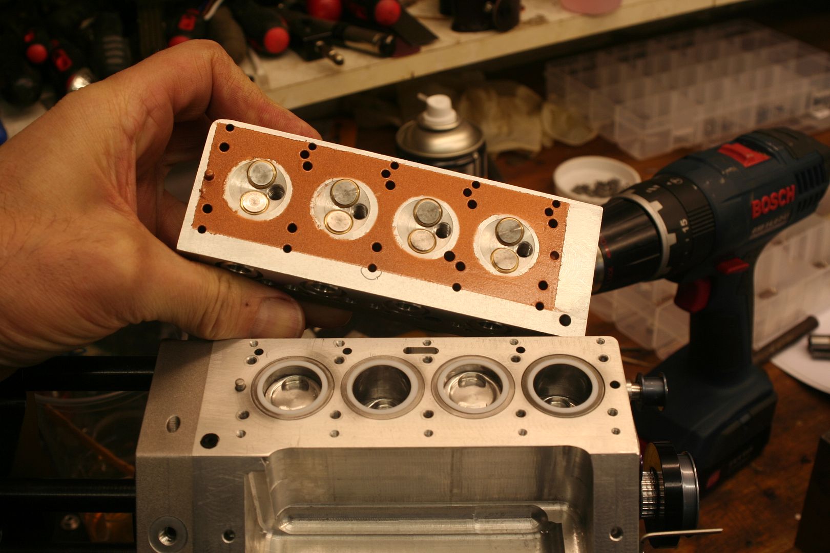
Bringing myself up to date now. Missed this photo showing the spray on head gasket and ptfe cylinder liner gaskets. The ptfe will crush up 4 thou with the heads on, so time will tell if they stand up to running.
I was planning on using full head gaskets, but there was no room for water bores in the new inlet manifold, so the plan is to rely on the cylinder cooling to cool the heads too. To make this work better though I wanted the head to contact the block without any insulation between.

Please don't copy this idea until I've tried it, it may be rubbish.

009-7.jpg


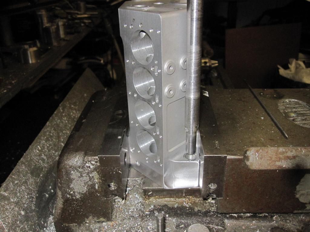
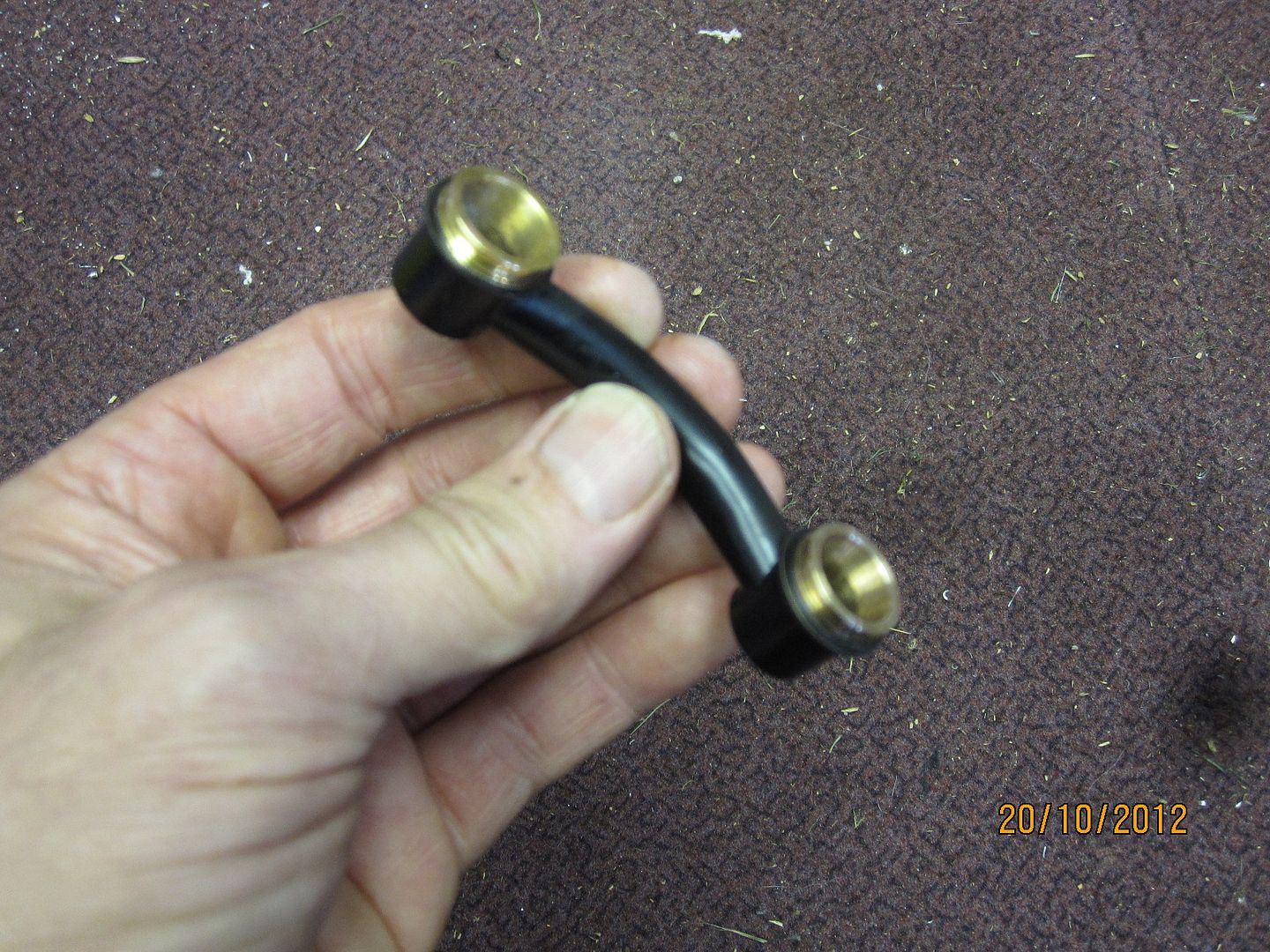
Exhaust header flange. More pics later on this..
001-5.jpg


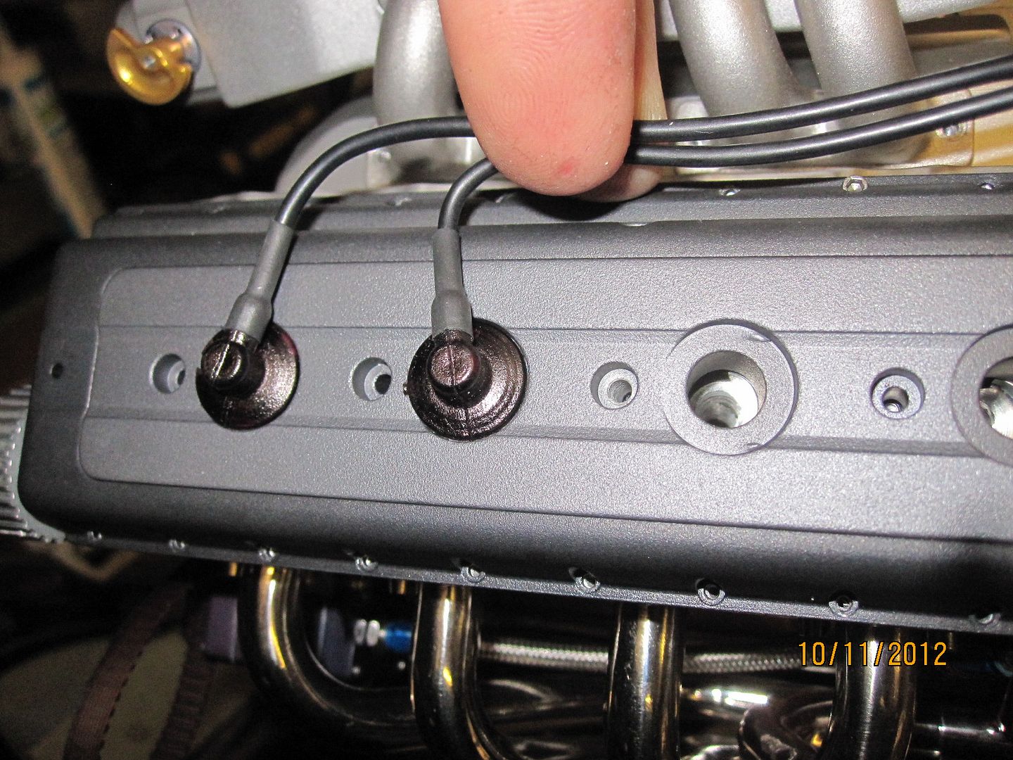
Spark plug caps, polyurethane mouldings. Not managed to cast a bubble free one yet!

002-7.jpg


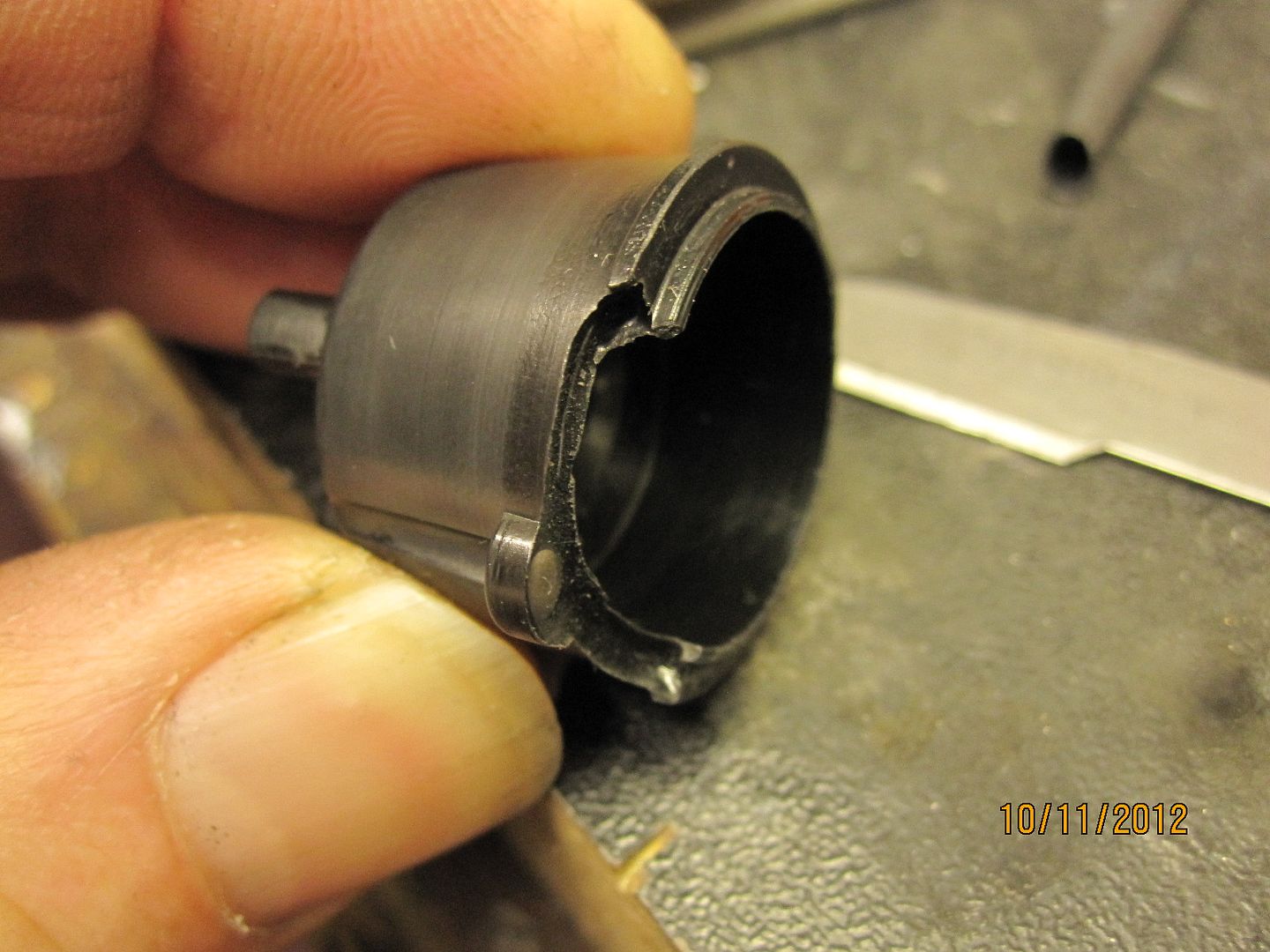
I decided to try an cast the dizzy caps at work. We have some hard polyurethane stuff which looks perfect for the job. Turned out to be more difficult than I thought.
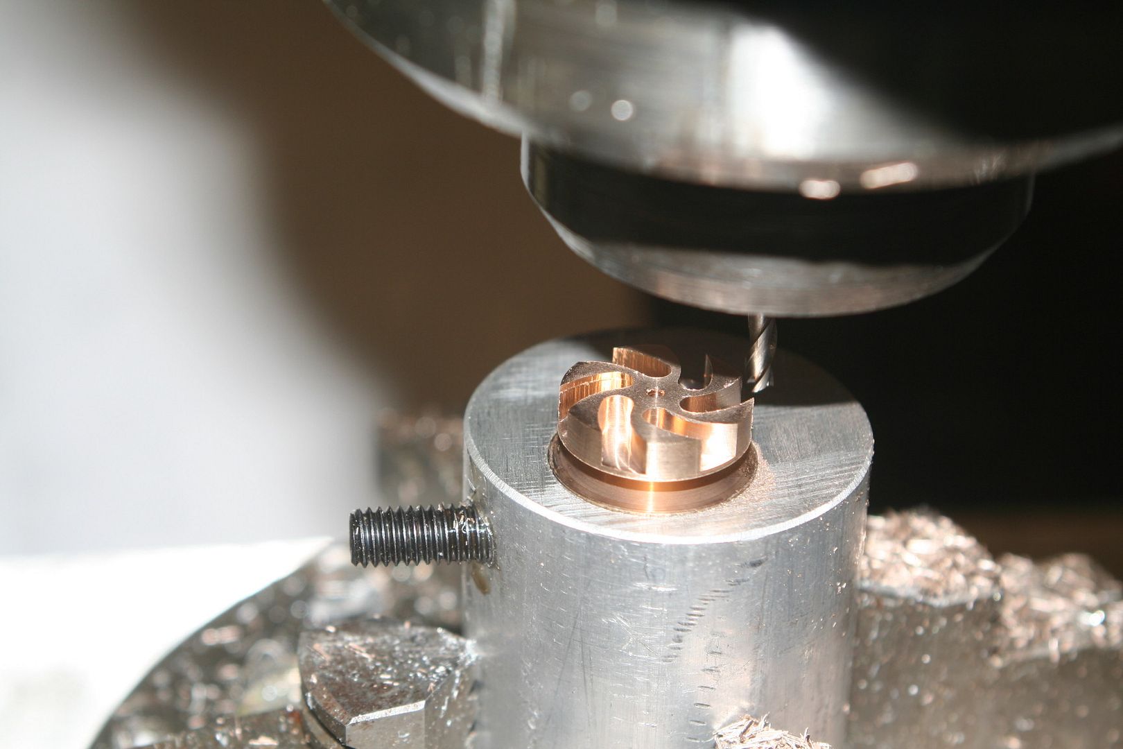
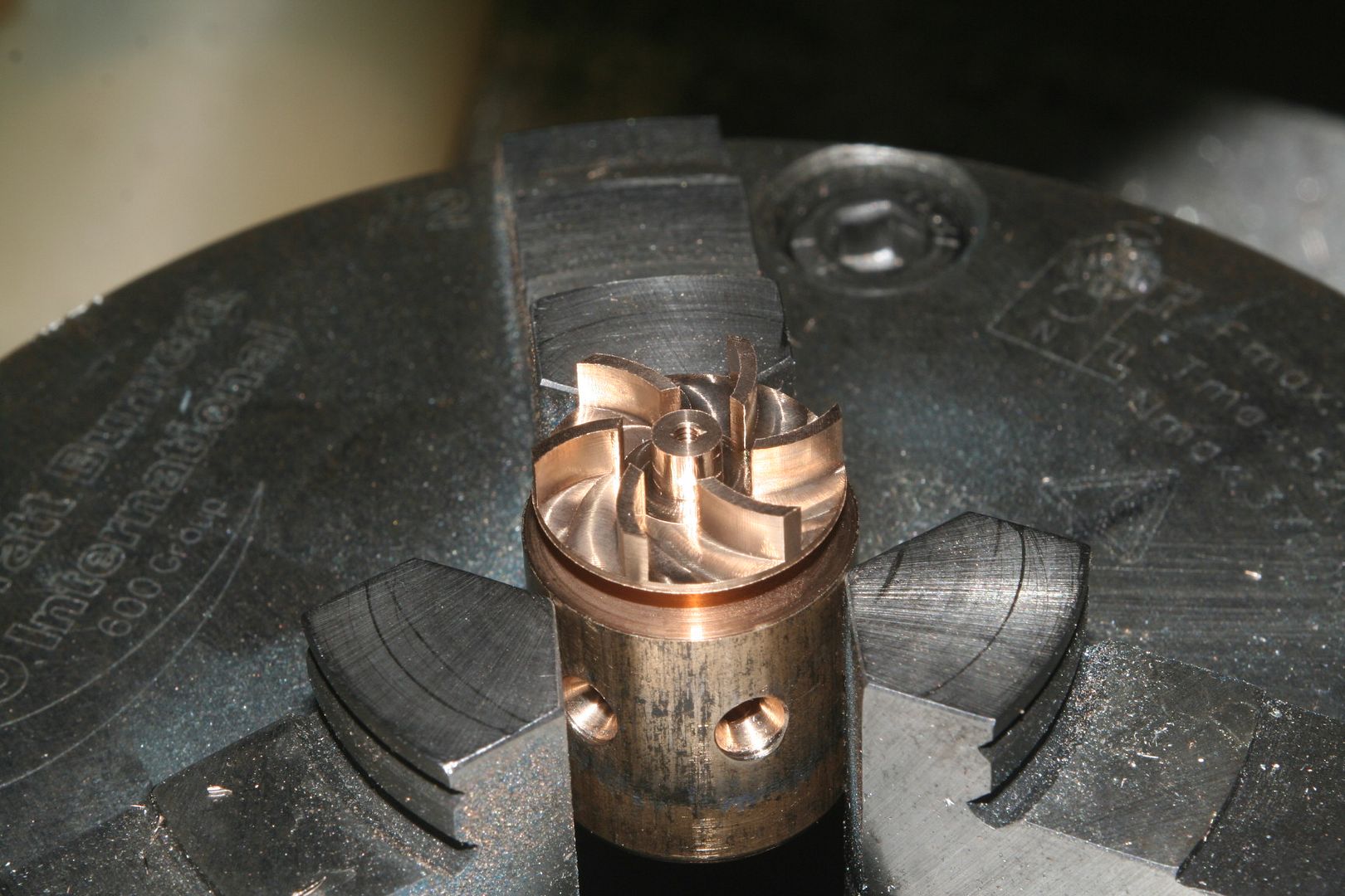
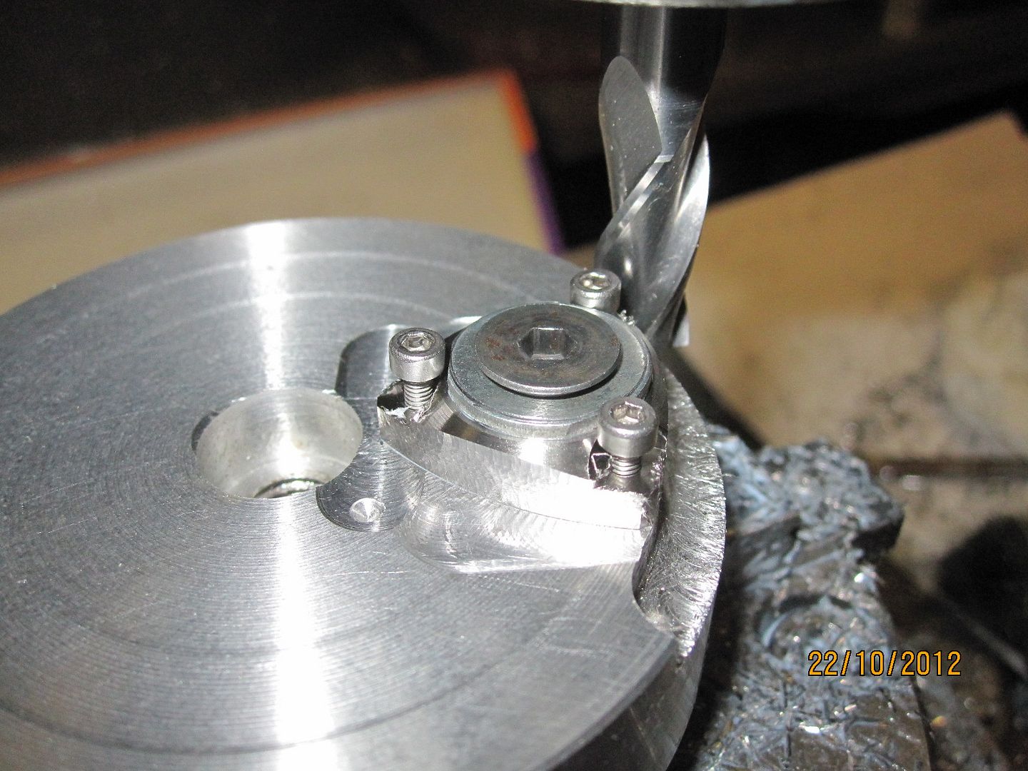
This is the mould..

005-6.jpg


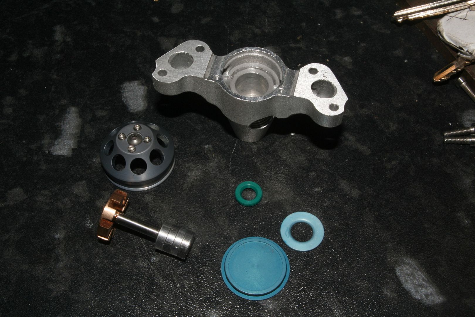
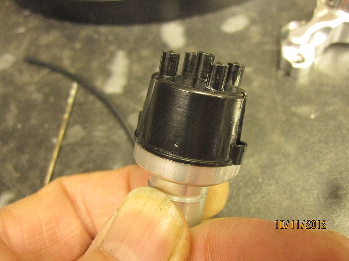
And this is the result so far. I need to re-design the mould and inject the poly under pressure,(syringe).

006-5.jpg


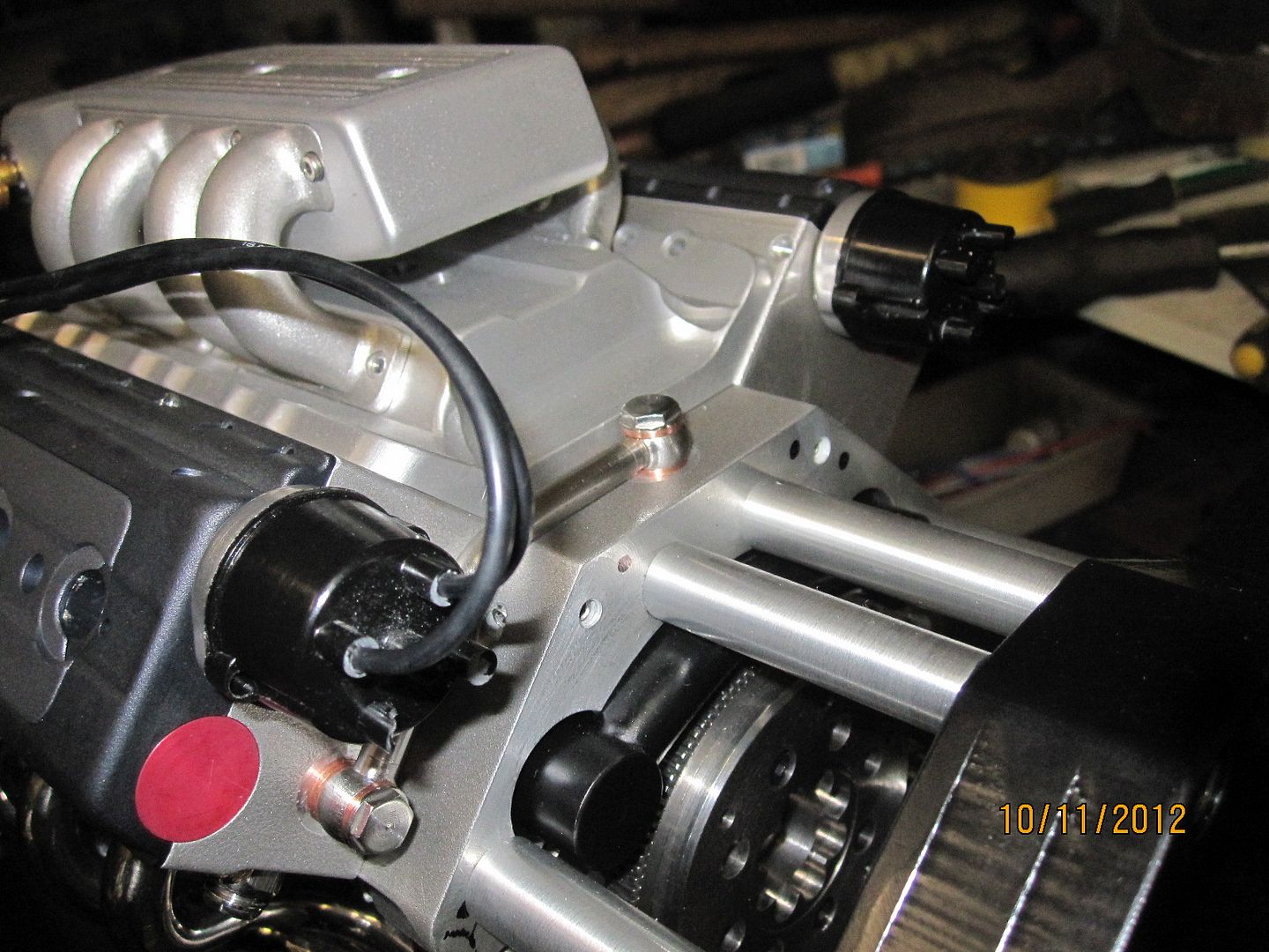
Actually I'm not too bothered with the bubbles as I don't really like these shaped dizzy caps on the end of the heads. I'll try and draw up a side mounted ht lead version.

007-1.jpg


Thought I'd try them for looks though...

003-2.jpg


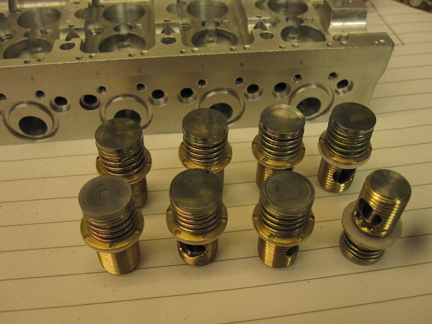
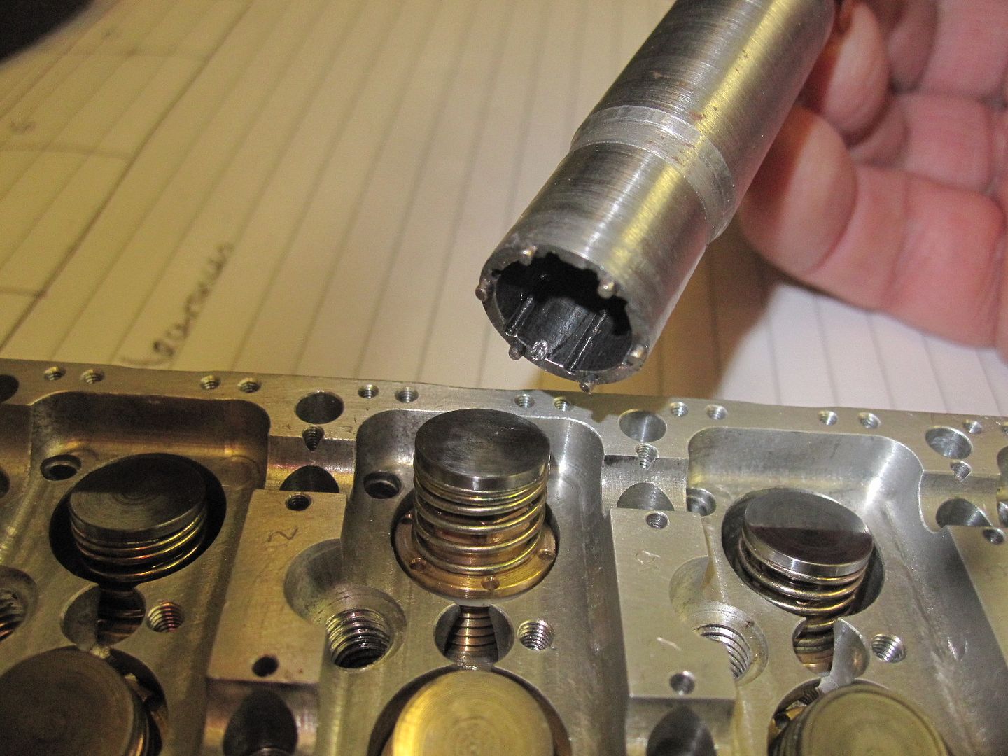
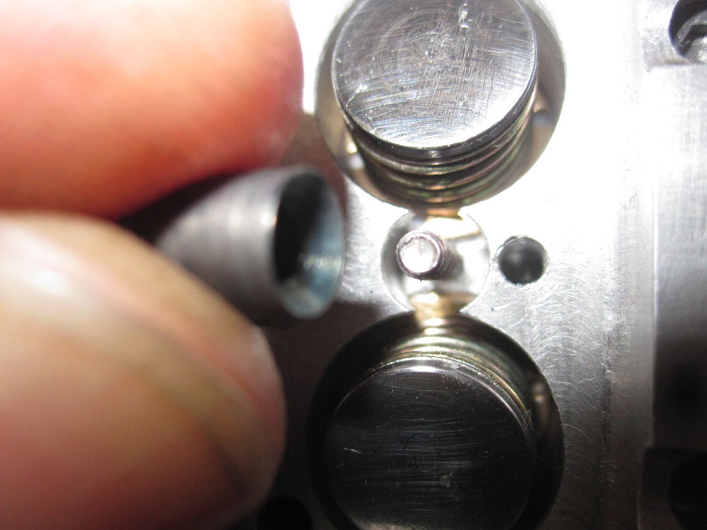
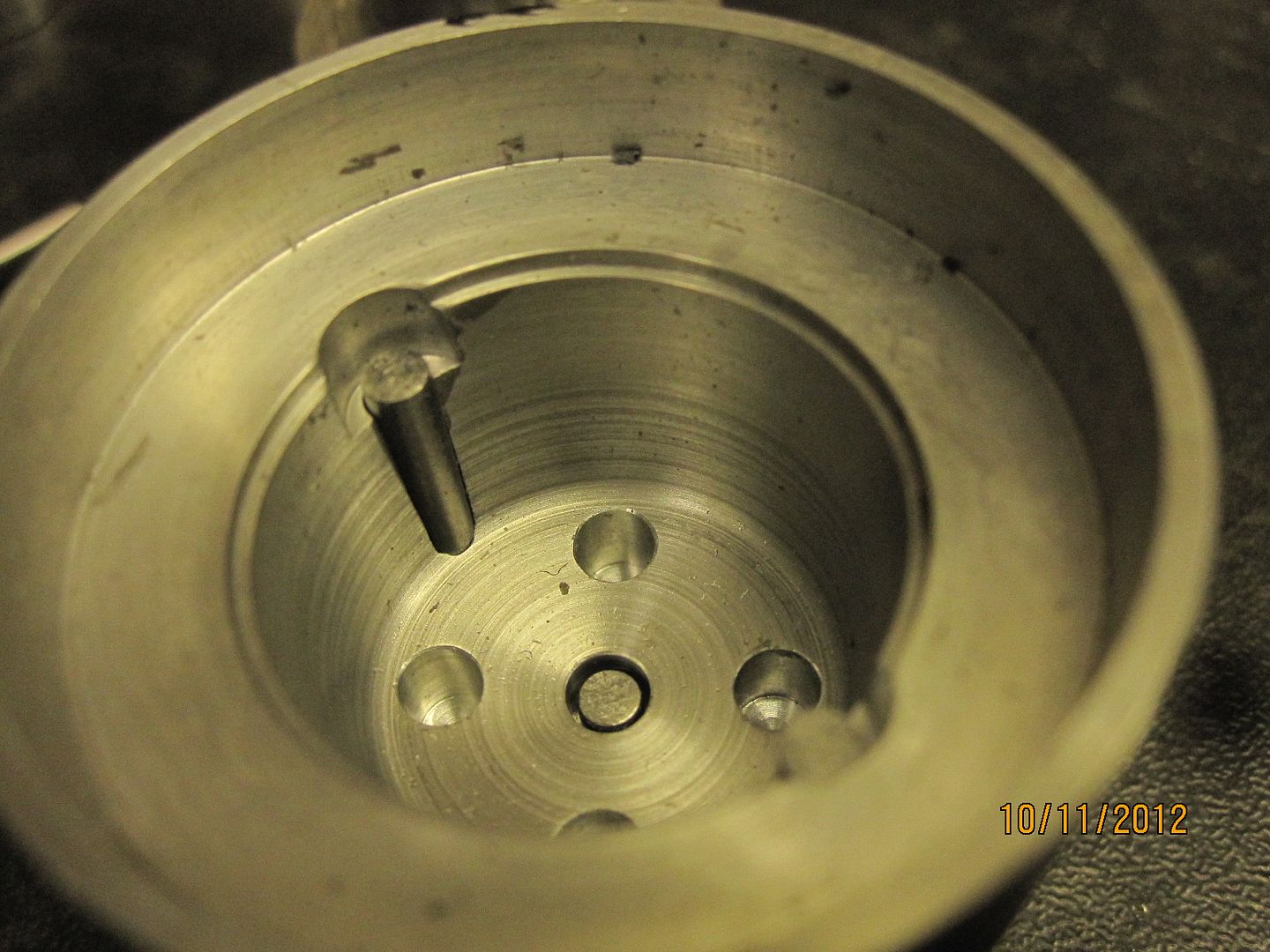
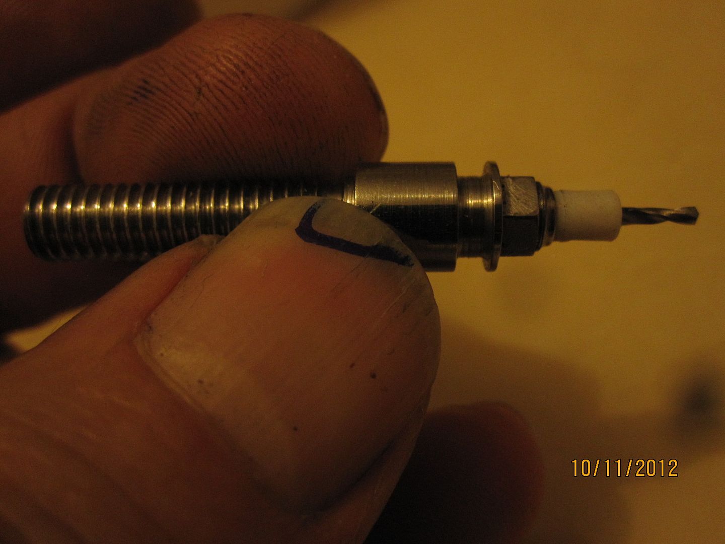
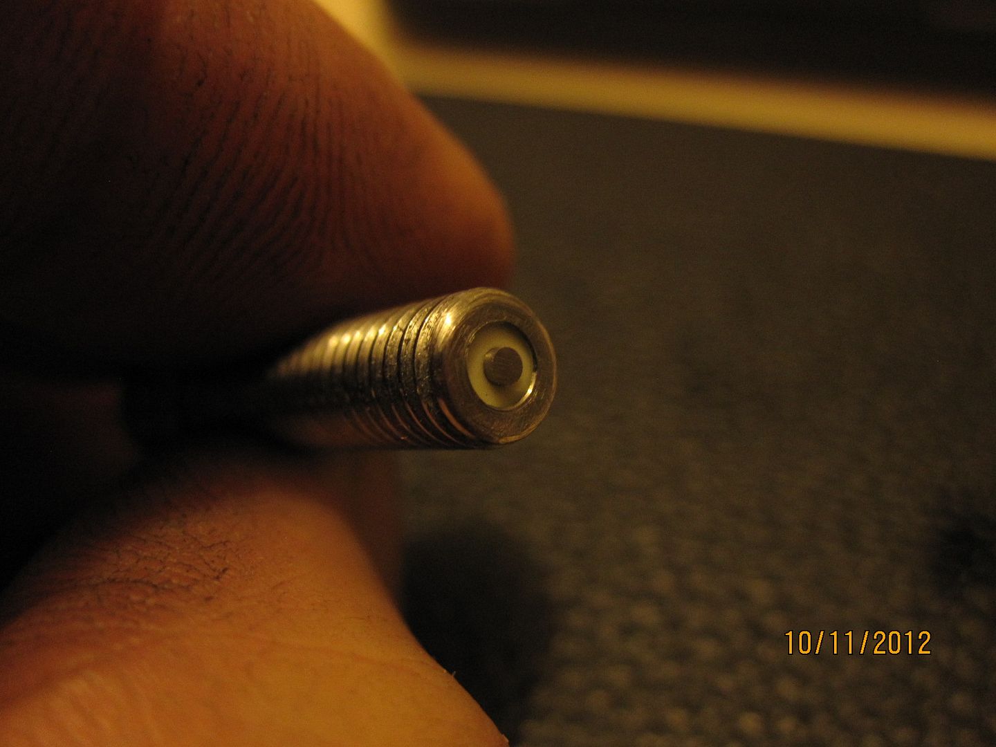
Got bored with the caps so had a go at a spark plug.

009-8.jpg


011-8.jpg


I found some ceramic tube on ebay, 3.5 o/d and 10mm long. This is pushed in to the hot end and the rest is ptfe tube. Can't really afford the macor, although that would be ideal.Cut the M6 thread with a die but the pitch was half a thread out in 20mm so won't go in the head.
Need to threadcut these then.
Also got no mechanical way of keeping the electrode in so need some high temp adhesive.
Given up for the day!
 
Keith,
Here's what I do to retain my center electrodes. My plugs are 14-32 and use Teflon as the complete insulator. When making the insulator I thread the upper end 3-48 for about .100. The electrode has a threaded brass cap soldered to it and is screwed into the insulator. I never had a problem with just pressing the electrode through an undersized hole in the Teflon but I thought this way would have added safety. Attached is a drawing of my plug design.
gbritnell

View attachment 4 CYL OHV SHT N.pdf
 
Props to you and your machining capabilities. Very motivating to beginning and experienced machinists alike.

Looking at your Valve Components (Post 87 page 9) I noticed I came up with the same setup for my 8 cyl radial engine. I was wondering what diameter the rod is and where you would suggest finding suitable springs, or home made with spring steel quenched and tempered? I have 3/8" dia valve head (1/4" big stem) valves and I have yet to find or make springs.

Ian
 
Last edited:

Latest posts

Back
Top