wooden faceplate for rotary tables

Home Model Engine Machinist Forum

Help Support Home Model Engine Machinist Forum:

This site may earn a commission from merchant affiliate links, including eBay, Amazon, and others.

hobby

Project of the Month Winner!!!
Project of the Month Winner
Joined
Dec 5, 2009
Messages
510
Reaction score
47
Hi guys,

Here is a quick tip for rotary table faceplates,
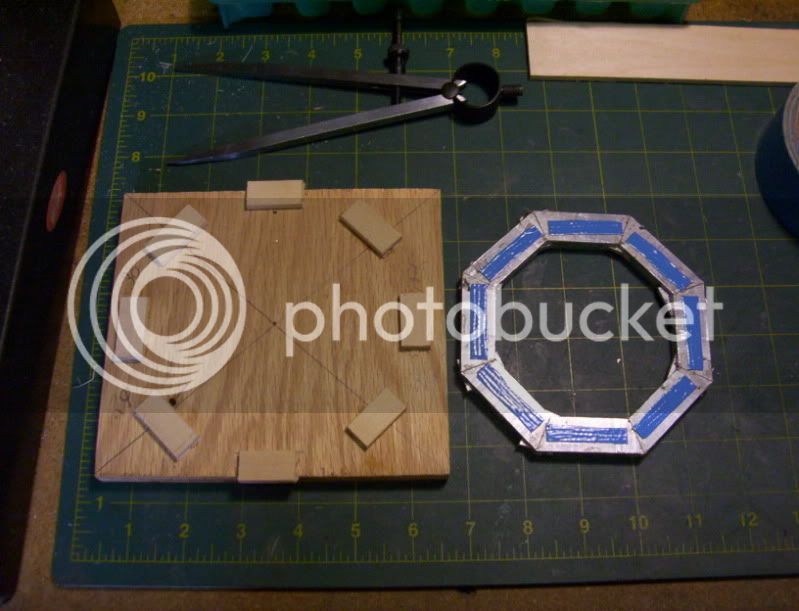
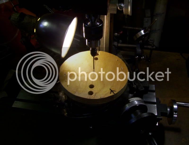
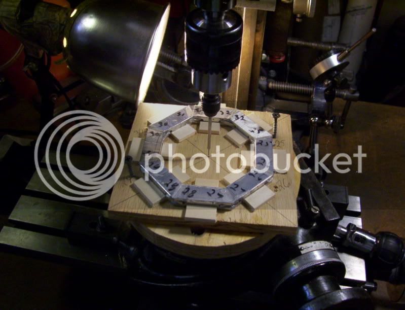
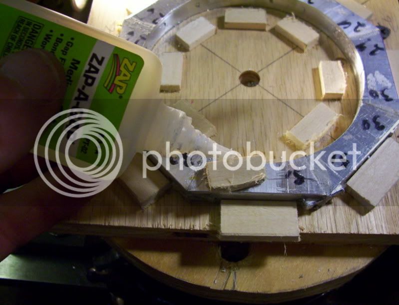
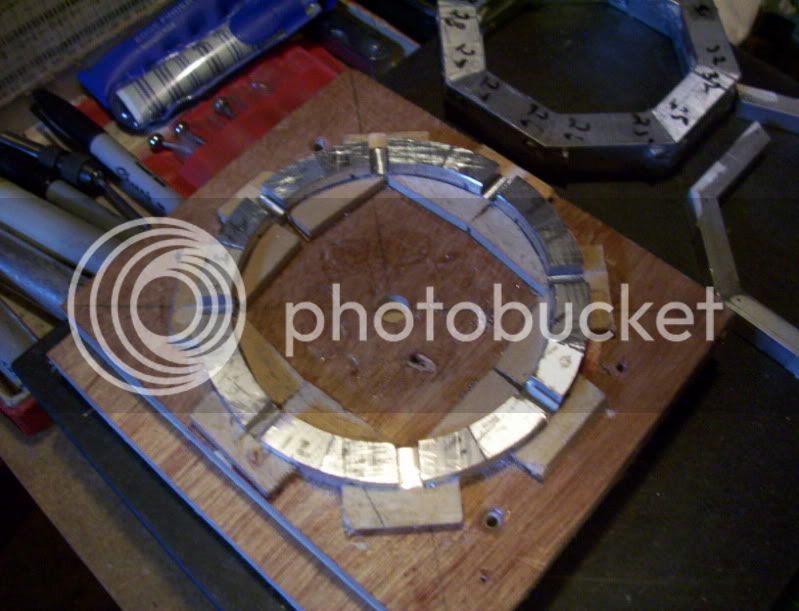
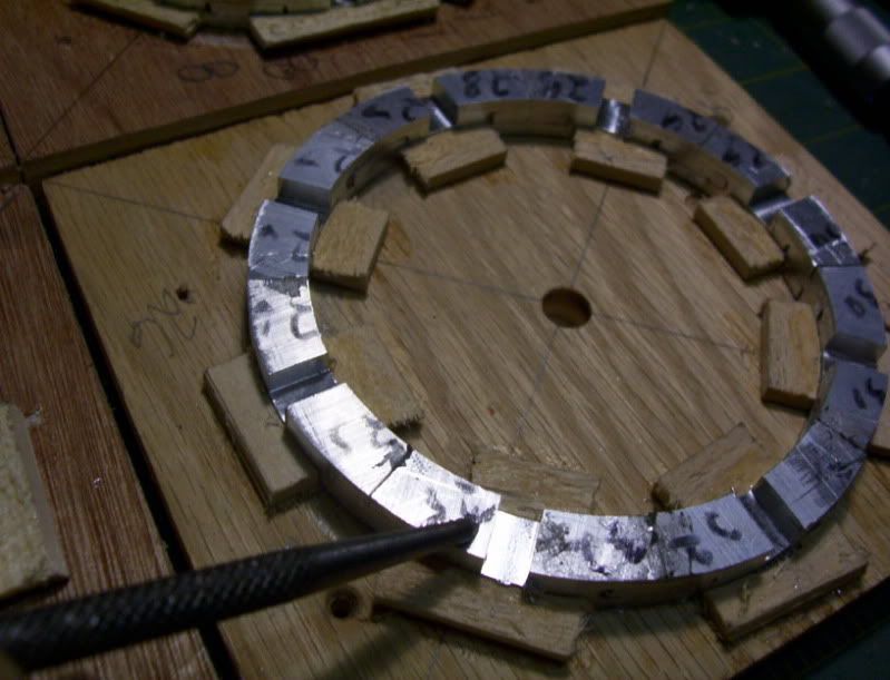
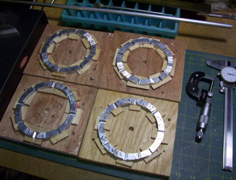
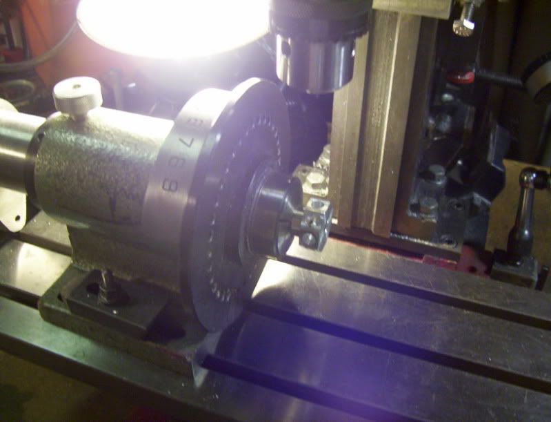
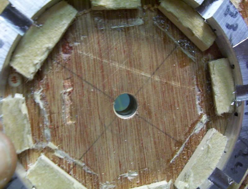
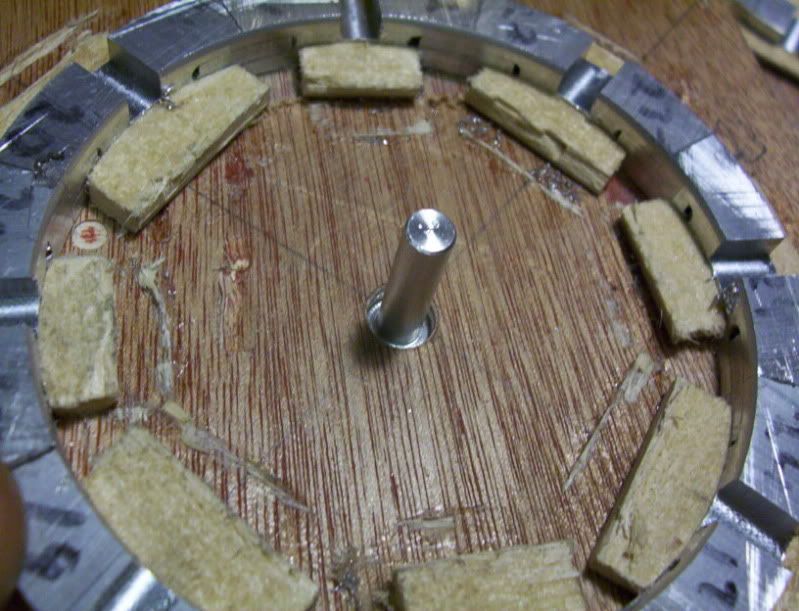
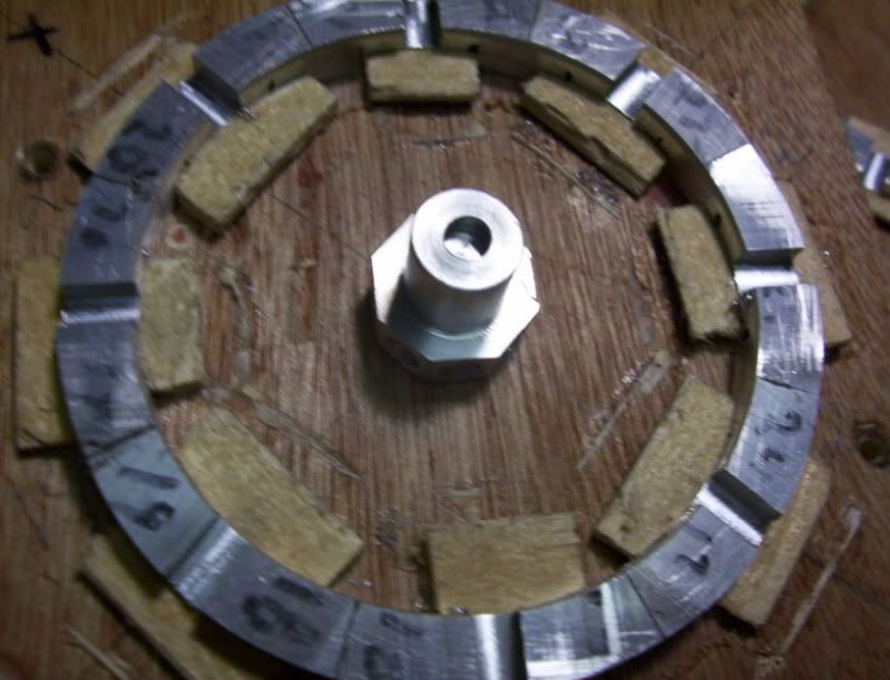
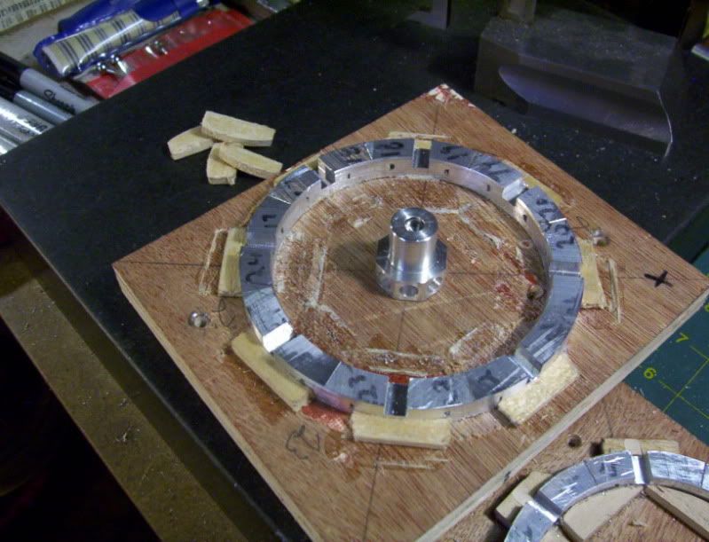
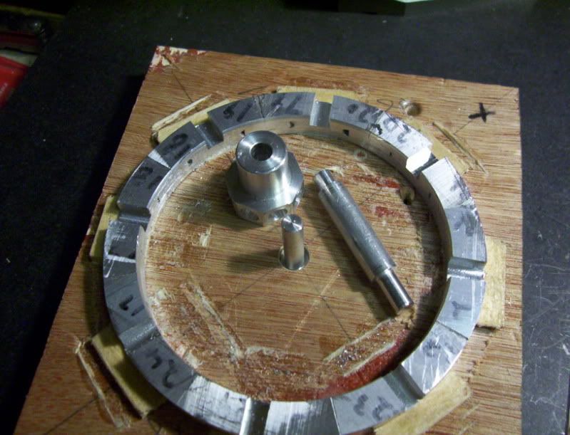
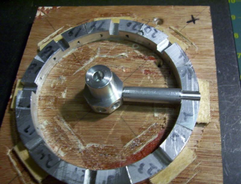
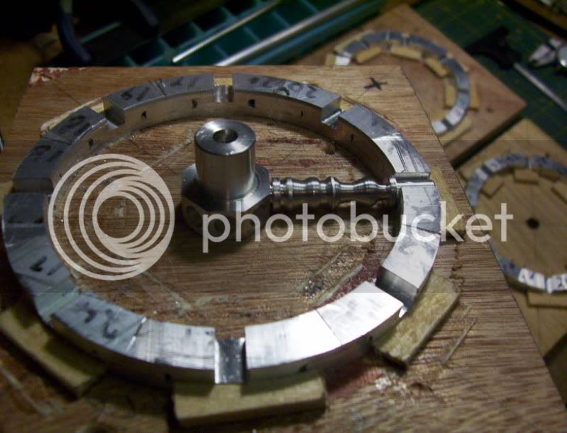
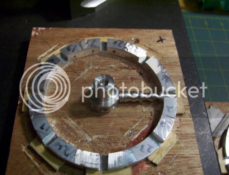
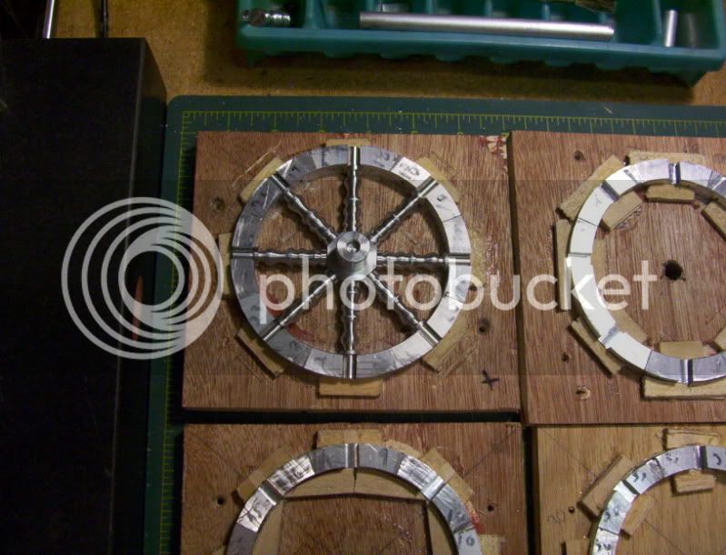
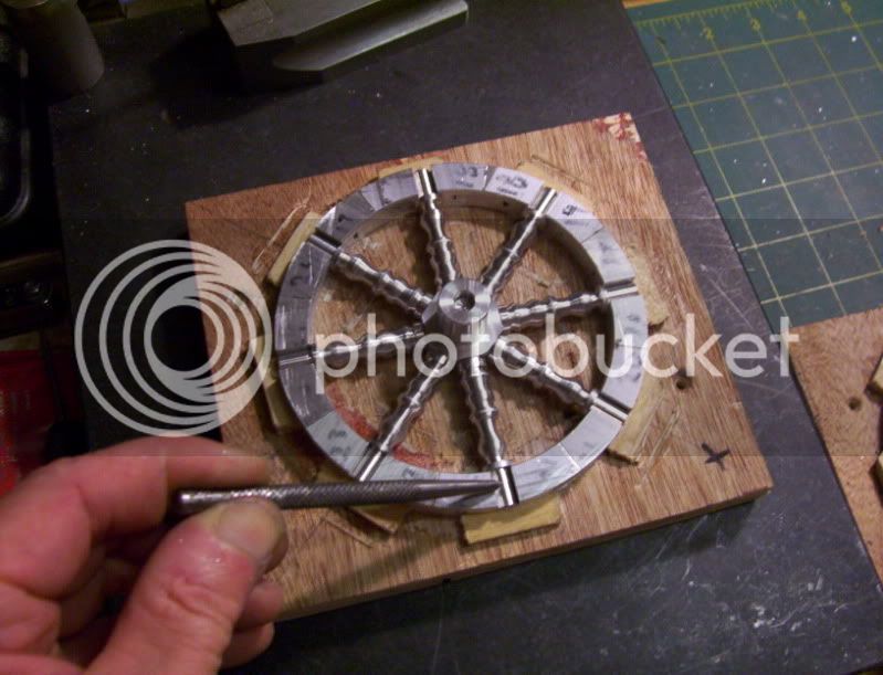
I have found that making a faceplate out of construction grade plywood, 1/2" to 3/4" thick works really well, as right now I am in the process of batching out scratch built flywheels, so I make a seperate plywood baseplate for each one, that holds all the work pieces in place, (these same baseplates are used as assembly jigs as well for each flywheel) then using double stick tape, and gluing on wood stops to make everything secure, than I line it on center on the rotary table plywood faceplate, and I can then screw it down to prepare for machinework.

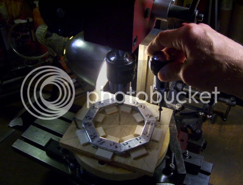
When thats done I take the next one and repeat the process, it saves a lot of time and material by using scrap wood blanks, wich with wood faceplates there is no tapping for holes, as with metal faceplates, but things can be screwed with drywall screws right in place.

I have found that wood jigs are really a good way to go for a lot of light machine work.
 
I like the idea of using the plywood as sacrificial work holders. I would like some pictures of your setup if you don't mind thanks dcflysrc
 
Hi,
dcflysrc

Here are some setup pics.

The real nice thing about this method is, I need to keep the flywheel rim intact with its plywood base from start to finish, because the center reference is used for milling out the circular profile of the rim, and afterwards, the reference hole in the center of this plywod jig, will recieve a locating pin, to place the hub onto, and then the spokes can be attached to the hub and the rim altogether, before removing the assembly off of this plywood base jig.

Here is one of the rim blanks ready for circular profile on the rotary table.

along side its plywood assembly jig.

The rim blank is 8 pieces splined together to form an initial octogon.

It will be double sticked taped to its base, then wood glueblocks to secure it from moving laterally.

100_3038_zps2e71e8c2.jpg


Since this is the second blank being milled, I need to recenter on the "x" axis the spindle with a reference hole previously drilled in the plywood face plate.

100_3039_zps06664636.jpg


And now the next rim blank with its sub base is centered as close as possible, onto the rotary table.

100_3040_zps7b507dd0.jpg


And this whole sub assembly can be screwed down with wood screws.

100_3041_zps124e8cc7.jpg


After I mill the inner circle, I pry off the glue blocks and reglue them tight up against the rim blank, at this point the glue blocks have been milled rounded along with the inner rim.

So the blocks match in closely to the inner rim profile.

100_3042_zps1a07f4cc.jpg


Then after the first milling operation is completed on the first two rim blanks.

100_3035_zps1e89ac17.jpg


This is one hub machined ready for fitting with spokes onto the rim wich will be permanently fitted together on the subbase, before removal.

100_3044_zps4dacf601.jpg


So each subassembly can be fitted with its own hub and spokes on the same sub base before removing them.

So the subbases act as sacrificial plates and assembly jigs all in the same setting, which is needed to keep everything concentric.

And all this subassembly is attached very easily to the rotary table plywood faceplate.


Thanks for the pics, quite an interesting manner of constructing flywheels. Would it be possible to see the process detailed from start to finish with pics and descriptions? I love the composite construction method and the possibilities are already running through my mind just seeing the pictures. This method would seem to lend itself well to using various metals to create quite unique flywheels.
THANKS DON
 
Hi,

I only took pics, for my own reference, so I didn't get a lot of detailed pics, but just some high points for me to remember,

so please excuse any inconsistancies in the procedures I describe here, I'll try to gather the pics and get them into a somewhat sequential order for clarity.

I started out mainly with a piece of 3/8" by 4" wide aluminum plate, and made some blanks to machine a 22 1/2 deg. angle on them to prepare them to be fitted as an octogon.

100_3014_zps850d2b91.jpg


100_3016_zps46072d39.jpg


This next picture is my first original cuts on the workpieces to check the angles, they were off some, so later I readjusted my angle vise to get a near perfect octogon, but I only took this picture, thats why it has some gapping between the last two pieces.

100_3018_zpsfb3499ab.jpg


after some fine measurements and tuning up with the machining I was able to get it to work together enough to be machined .

100_3020_zps44bbcbf5.jpg


100_3021_zps8edfd4e3.jpg


Then the next procedure is to mark each piece, and take two pieces and match them together as a 45' angle, and set them in the vise and machine a slot through the top edges the width of a spline to fit into, the same way you fit a spline to a miter joint in wood frames.

100_3022_zps81fc9f43.jpg


100_3023_zps90302966.jpg


100_3024_zpsba038023.jpg


Then when all the pieces are splined together to form a octogon blank, I then took them apart and applyed epoxy glue to all pieces and reassembles foe a permanent bond.

100_3036_zps58bbdd4c.jpg


And the attachments and machining of each rim blank, as was described in the last post.

I have copied and pasted these procedures here as well.

Here is one of the rim blanks ready for circular profile on the rotary table.

along side its plywood assembly jig.

The rim blank is 8 pieces splined together to form an initial octogon.

It will be double sticked taped to its base, then wood glueblocks to secure it from moving laterally.

100_3038_zps2e71e8c2.jpg


Since this is the second blank being milled, I need to recenter on the "x" axis the spindle with a reference hole previously drilled in the plywood face plate.

100_3039_zps06664636.jpg


And now the next rim blank with its sub base is centered as close as possible, onto the rotary table.

100_3040_zps7b507dd0.jpg


And this whole sub assembly can be screwed down with wood screws.

100_3041_zps124e8cc7.jpg


After I mill the inner circle, I pry off the glue blocks and reglue them tight up against the rim blank, at this point the glue blocks have been milled rounded along with the inner rim.

So the blocks match in closely to the inner rim profile.

100_3042_zps1a07f4cc.jpg


Then after the first milling operation is completed on the first two rim blanks.

100_3035_zps1e89ac17.jpg


This is one hub machined ready for fitting with spokes onto the rim wich will be permanently fitted together on the subbase, before removal.

100_3044_zps4dacf601.jpg


before I removed them from the rotary table I used the RT to position the blanks every 45 deg. so I could mill a 1/4" slot through the center of each segment, half the thickness of the rim, to recieve the tenon of a spoke.

100_3046_zpsde5196de.jpg


Now I have the blanks machined to the rim profiles,

100_3045_zps784d3059.jpg


After that I machined a hub blank on my lathe, and then positioned it in my dividing head, so as to mill a flat, and drill a 1/4" dia. hole every 45 deg. This will recieve the tenon on the other end of a spoke.

100_3047_zps4826d689.jpg


Now a made a locating pin to fit in a subbase to locate the hub, so as to prepare it all for final assembly.

100_3048_zps342f38fd.jpg


100_3049_zpsc01c0bb3.jpg


100_3050_zps229bdafb.jpg


100_3051_zps64f1b30e.jpg


Thats all for now, I now need to start machining the spokes, I'll take some pics, of the process, as there will be some tenoning needed to be done, as well as some decorative forming on each spoke, so when I start that procedure I'll post some more pics


Hi,

This is post 2 of 2 in this sequence of posts.

Please look at the post above which is the first part of this discription of this build sequence, and
here is a continuation I said I would bring when I start making spokes.

one spoke blank is machined in my lathe with a tenon on each end for the hub and rim.

100_3052_zpsc54611a8.jpg


100_3053_zps8818057f.jpg


100_3054_zpsbb9ee981.jpg


I'll need to machine this tenon to fit inside the rim slot with a half lap joint.

100_3055_zps196839ca.jpg


But before I do that I need to take care of any decorative profile work on the spindles.
This step is optional, I chose to have decorative spokes for my flywheels, so here is one form tool I'm making to do this profile work.

100_3056_zpsbcf1de15.jpg


100_3057_zpsc2adef82.jpg


100_3058_zps359e6190.jpg


check for fit.

100_3059_zps8dc8e1f5.jpg


This step is needed for all the spokes, now I reinsert the spoke into my dividing head collet, and machine half the diameter.

100_3060_zpsdb2537ff.jpg


and now the final mockup of how the spoke will look assembled to the hub and rim.

100_3061_zpsb7cc5379.jpg


100_3062_zpscaeb171f.jpg


I may also fill in the gap above the tenon on the rim side, I'm not sure yet what I will do with that area.

After the flywheel is permanently assembled, I'll fit it on a mandril, to use my lathe to turn it to a final finish, and concentricity, balance.

I hope this helps you get some understanding of the process involved.

Have a great day.
 
Here is the spokes all made and dryfitted, next I'll permanently attach them by gluing the tenons on both ends to the rim and hub.

100_3063_zpsd2a96c34.jpg


Then after that I'll return this whole assembly to my rotary table on my mill, and drill so as to pin the spokes at there respective tenons as shown.

100_3064_zps519dd41d.jpg


As can be seen the original subbase that was used as a fixture for machining the rim, is now serving the purpose of being used as an assembly jig.

And being made out of wood, makes for a very affordable way of batching out several flywheel builds at a time.


Have a great day...
 
Thanks for the pictures and explanation of your flywheel building. It is always nice to see what others are doing and the setups that they use while doing it. Mounting the wheels to the wooden plates is a great idea and nice in the fact that it is sacrificial. I really like the moulder/planer style of form tool you use for the spoke section as well. Great stuff and THANKS FOR SHARING!!
 

Latest posts

Back
Top