Valve Seal Test Chamber

Home Model Engine Machinist Forum

Help Support Home Model Engine Machinist Forum:

This site may earn a commission from merchant affiliate links, including eBay, Amazon, and others.

Brian Rupnow

Design Engineer
Project of the Month Winner
Joined
May 23, 2008
Messages
15,012
Reaction score
8,307
Location
Barrie, Ontario, Canada
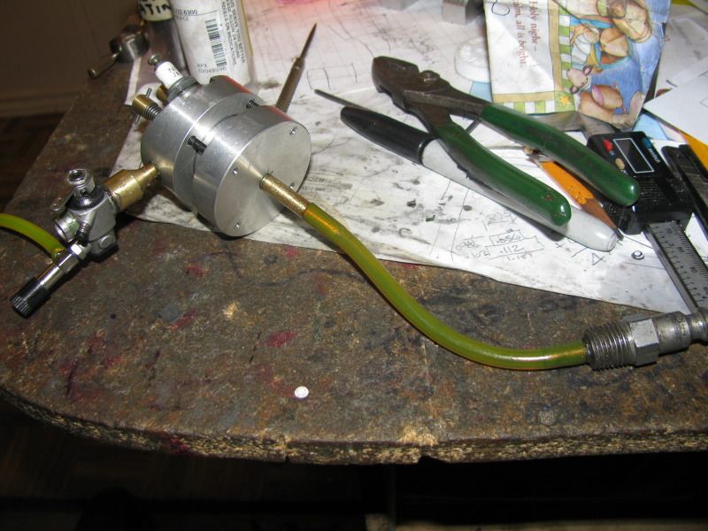
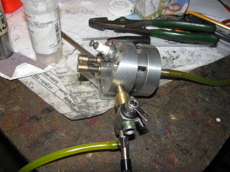
It seems that in spite of all the care I took when machining and assembling my Atkinson engine, I have a leaky intake valve. Perhaps not leaking badly enough to prevent the engine from starting, but leaking, none the less. As I go through all the possible causes for the engine not starting and try to eliminate them, one thing popped up. Its a miserable chore to pull the head off the Atkinson once its all assembled, so I needed a way to test for leaking valves BEFORE assembling the head to the engine. So---I made a pressure chamber. This is simply a round peice of aluminum the same diameter as the cylinder, with the same bolt pattern as the cylinder, and an internal cavity which I can pump air into from my compressor. It is turned down to a diameter that fits into the recess in the cylinder head, and the internal chamber is big enough in diameter to miss the heads of the valves. I put a ring of gasket material between the test chamber and the cyl head, then carefully snugged down the 4 cylinder head bolts. Now I can pressurize the chamber with my compressor, and it immediately shows up a leaky valve. You can hear it hissing at the carb throat or the exhaust manifold. I am probably going to have to make a new intake valve cage ---maybe even a new valve. Ah well, bad on me. I thought that the pressure chamber idea might help some other poor sod who is attempting to build a 4 cycle engine.---Brian
VALVETESTCHAMBER002_zps86704ae7.jpg

VALVETESTCHAMBER001_zps13ab3353.jpg
 
If there is a chamber on the bottom of the head you can turn it upside down and fill it with barsol or other fluid and it will drain down if the valves are leaking. Use this method on automotive heads all of the time.
 
Great idea. Many thanks for sharing
 
Last edited:
If there is a chamber on the bottom of the head you can turn it upside down and fill it with barsol or other fluid and it will drain down if the valves are leaking. Use this method on automotive heads all of the time.

Did that lance. Left it half an hour with paint thinner in it.--No leaks!! But it still leaked air.
 
Brian,
I have a collection of hollow sparkplug bodies into which I have silver soldered a pneumatic quick coupler.

I use this on suspect full size engines - replace the spark plug with the adaptor - set engine to TDC and apply pressure, listen at exhaust / inlet / crankcase for leaks.
If you feel like it you can determine the leak rate by the pressure decay on the reservoir.

Obviously you are checking both valves and rings at the same time but I find it generally turns up the culprit.

I just completed an automatic head testing machine using ATEQ leak testing equipment of the Volkswagen 16 valve head - the permissible leak rate per pair of valves is 5cc/min @ 5 Bar - FYI

Ken
 
I am surprised that the thinner didn't leak out. I would surmise that on a model the valve sealing is much more critical than an automotive application. I can feel your pain on this one. Been there and done that, had the head off of a 4.6 ford pickup 3 times to the machine shop, (right side which is no picnic) to finally find out that they had ground the seat to much causing the valve to stay open enough to cause a misfire. I finally popped out the cam follower and ground the stem.
They do make a tool for problem like this.
http://www.ebay.com/itm/Engine-Cyli..._Automotive_Tools&hash=item35bfc23183&vxp=mtr
 
I have tried just about all of the methods for verifying the seal of engine valves. In my opinion, the best, and easiest use method for leak detection is the simple brake bleeding hand vacuum pump equipped with vacuum gauge. It readily indicates any leaking valve and also gives you a very good idea of the severity of any leaking valve that you find. They are available from Harbor Freight and are on sale frequently.

Jeff
 
Another trick I have used, particulary when I don't know where a leak is, is to fill the cylinder most of the way with WD-40 or similar and to hydro lock the engine. Hold pressure using the flywheel and see where the fluid comes out. Just this morning I did that and found a leaking o-ring head gasket that I wasn't even thinking about as a possible problem.

Lee
 
I'd like to re-activate this thread...

I'm nearly finished with my Hodgson 9 cylinder radial and the build has been going well. I decided to depart from the original planset and use phosphor bronze valve cages instead of just pressing in seats as the original author did. After (lightly) pressing in and loctiting the cages I made a piloted seat cutter by drilling the center of a quality HSS 90 deg 6-flute countersink and then pressing in a pilot which I then turned concentric to the countersink in a 4-jaw chuck. I then manually cut a pair of seats on a spare test head to a width of .010" to .015". Checking the seats with a permanent marker painted on the valves I get perfect 360 deg patterns showing full contact. Looking at the seats under a microscope I can see only minor machining scratches. So, I built a pressure test fixture which was easy since my heads are threaded on the bottom where they will eventually thread onto the cylinders. I was expecting perfect results since I have accumulated some experience with seats after previously building two other multi cylinder IC engines with similar cages. (I spent many, many hours on these engines getting the seats to a 'satisfactory' state of seal). However, to my surprise, both seats leaked like crazy bleeding the 30 psi pressurized chamber down to zero in only a few seconds. So I decided to lap the valves (something I thought I wouldn't have to do after seeing such nice contact rings on the valves). I first tried the extra-fine Timesaver lapping compound which is listed as 100g but seems much finer to me. The leakdown results were about the same but maybe a little better. I manually lapped two or three times for a total of 3-4 minutes. I then used 1200 g Clover and the best I was then able to achieve was leakdown from 30 psi to 10 psi in about 20 secs. Submerging the pressurized head in kerosene definitely show lots of bubbles in both ports proving the leaks are in both seats and that both leaks are similar. I also checked the heads by filling with alcohol and see no obvious liquid leaks. I also did a "blow test" recommended by someone online by pressurizing the submerged chamber by blowing into it while watching for a maximum of 5 bubbles. In this test I saw no bubbles. Both of the valves show nearly identical leaks in the 30 psi test and I'm absolutely amazed that they are so bad after all the care taken to this point. In my last 4-cylinder engine I settled on a metric for testing my seats (after many hours of work) which used a vaccuum pump (Mity Vac) to suck on the valve behind the seat. My arbitrary goal for that engine was 10 psi leakdown in 15 secs or more, and after making a piloted seat cutter and lapping the seat I eventually got all the seats to pass this test. So, as a comparison I tried this same test on my test head and I essentially see no leakdown (OK, maybe 1-2 psi in 30 secs). So now I am really confused. I would think the pressurized chamber test would be the best test, but I don't understand how with all the careful lapping both valves seem to leakdown indentically. (I did verify my test equipment by applying some heavy oil to the seat and this does stop the leak.) My 4 cylinder engine starts and runs well and the Hodgson probably will also, after lapping the valves; but has anyone else actually done a pressurized test and if so what results were you able to achieve? I realize I'm probably being anal here but I have 20 valves to do on this engine and I want to make sure that I don't end up having to re-make these heads because at 60 hrs per that will be a deal breaker. Does anyone know how fast a good condition full size engine will leak down? - Terry
 
Not that I can shed any light on this, but do you have the springs installed? I know that when I worked on VW heads, I got terrible results before installing the springs. I tried using weaker springs, but they were never satisfactory.

I don't remember what the minimum leakdown time was, but I always tried to get it to greater than 10 minutes.
 
There are a few things to understand, before waisting time:

Leak tests are done with gasoline, or a *very* thin oil like diesel. If the seat doesn't leak, it is considered tight (enough).

Testing is done with the springs installed.

There is no use to test leakage over minutes or hours. If you look at how long the valve is closed when the engine is running, you can imagine how little it will leak in that time. That is a dynamic process, to some extent similar on how a piston seals (with its oil film).

The seat in a small scale is made different. If you scale down a valve and its seat of a car engine, you will see that the seating strip is very narrow, just a few tenth of a mm. So do NOT machine the 45° seat, but leave a sharp corner. Lap that down with the valve and you are done.

It still is *very* essential that the bore for the valve's stem and the seat are concentric.


Nick
 
Mayhugh1--Welcome to my world. Sometimes it seems to be far more a matter of luck than of any technical expertise. The only other thing I can suggest is to grind or machine the seats at 45 degrees and the valve faces at 44 degrees , thus giving a true ring contact and then lapping very lightly. Thats what I did with the leaky valve on the Atkinson I just finished, and thats what ultimately got me to a valve that really sealed.---Brian
 
Terry,
Valve seates can be a bugger. I will give you my method for making and testing valve cages. It may not be the best method, but it has worked well for me. I generally use aluminum, or phosphor bronze for my valve cages, but brass has also work satisfactorily in one of my engines.

I do the valves and seats using a 45 degree compound setting without disturbing this setting during the whole process. I machine the valve cages to size for a heat shrink fit in the head.The next to the last step is the valve guide bore. I use a starting drill, and then a stubby drill, followed by a reamer. The better procedure would be to drill, bore, and then ream but I have never been able to see the guide bore inside the cage well enough to bore it. Without disturbing the cage setup, the last step is to cut the seat. I make the seat very narrow using a sharp radiused tool bit. When all the cages are finished, I then cut my valve seat faces using the same compound setting. If you can use collets for holding the cages and valves, it will improve the concentricity. Next step is to lap the valve seats.

I don't use Timesaver compounds for seat lapping. Timesaver is a non embedding abrasive that is designed to cut initially and then quickly break and stop cutting. I use Clover #600 or #800 grit lapping compounds. I use a pin vise to hold and twist the valve stem, pulling up on it only enough for the valve to make a firm contact with the seat. No heavy pressure is needed. It is important to not make 360 degree revolutions of the valve when lapping. A 90-120 degree back and forth twisting rotation is proper, then lift the valve off the seat, rotate it 90-120 degrees and lap a few more twists. Keep moving this lapping action until until you have made a few complete revolutions with the valve. Now test it.

Clean the seat and valve with brake cleaner. If you have a close fitting guide and stem, a drop of heavy weight oil will seal it for testing. I install the valve spring and keeper and work the valve a couple times allowing it to seat itself. I then apply a vacuum to the valve port in the head. I use a Mityvac hand vacuum pump. Pump down to 25" Hg. If you can't get to 20" with quick pumping action, the leak is significant. With the above method, I can usually pump to 25" Hg, and a good sealing valve will not leak down lower than 15" Hg within 15 seconds. If it does leak, lapping it one or two more times usually will correct the leak. If you have a leak, first make sure the leak isn't in the guide.

If you want to make a piloted seat cutting tool, I would make one similar to one that was shown on HMEM by G. Britnell some time ago. Sorry I can't give you the link, but someone else might be able to post it.

Jeff
 
There are a few things to understand, before waisting time:


There is no use to test leakage over minutes or hours. If you look at how long the valve is closed when the engine is running, you can imagine how little it will leak in that time. That is a dynamic process, to some extent similar on how a piston seals (with its oil film).

Nick

Nick, I once thought that leakdown over several seconds wasn't important either until I built my first IC engine - a Howell V-twin - with twin carbs. Those seats leaked down about 10 inHg in about 7-8 secs and the compression felt good when the engine turned over by hand. It started and ran but I noticed when I placed my finger between the two carbs' velocity stacks (they were facing toward each other) I could feel a cool spray of fuel when the engine was running and in addition one cylinder was running much cooler than the other. At first I thought my valve springs weren't strong enough and were bouncing on their seats, and so I made new ones. The problem was still there. I eventually traced the problem to an intake valve that leaked down faster than the other three. After a few hours of mis-directed re-cutting and lapping I re-assembled the engine and the problem was gone. What was happening was when the leaky cylinder fired, the combustion gas leaked past the seat and blew through the carb. In a single plane intake manifold on a multi-valve engine this gas will blow through the carb and prevent the fuel charge from getting to another cylinder that is on its intake stroke during the time the cylinder with the leaky valve is firing. I imagine this problem can really have you chasing your tail while looking in the wrong place for problems with a mis-firing cylinder- Terry
 
Those seats leaked down about 10 inHg in about 7-8 secs ...

That's 0.34 bar. Would be interesting to know wether it would have passed a test with gasoline/diesel. But I bet you won't disassemble it again just for my curiosity. :)

That blowing back into the carb (and even out of it) is very common, especially with two strokes (without a reed valve). But also 4-strokes do that, if you look at the timing diagram.
If you have ever seen a video on YT of a F1 engine looking into the intake... It looks like fog coming out of the intake.


Nick
 
After another dozen hours of experiments and tests and comments by others, I think I finally getting a picture of what's going on. First, some question why even test for leakage and why worry about leaks that are slow with respect to the length of the compression cycle at the lowest rpm of the engine? For a single cylinder engine built primarily for occasional running but mostly display purposes the main need is to develop enough compression for starting and sustaining running at the lowest rpm desired. But for a multi-cylinder with a single plane intake manifold all the cylinders are drawing their fuel from a common manifold typically fed by a single carburetor. This means that while one cylinder is firing, another cylinder is drawing in its intake charge. If there is significant blow-by from a leaky intake valve from a cylinder on its firing cycle, it will interfere with the fuel distribution to the other cylinders, leaning them out, and in the worst case it will blow most of the charge back out through the carb causing an otherwise perfectly good cylinder to misfire. A very similar problem happened to me on my Howell V-twin. This engine has separate carbs for each cylinder. When runnning, both cylinders were firing but one was running considerably cooler than the other and I could feel a spray of fuel pulsing out one of the carbs while it was running. At first I thought it was a weak valve spring but later discovered it was a leaky intake valve blowing gas back through the carb and carrying fuel with it. Since the carbs were in close proximity and facing one-another the spray from the leaky cylinder was in fact richening the mixture for the other cylinder. Turning the engine over by hand one could feel significant compression on both cylinders and since it was my first engine I had thought this was a sufficient test. When I built my next engine, a Howell V-4 which is a single plane manifold with siamesed runners and a single carb, I knew I had to do a better job with the valves and I needed a way to test them. This build was complicated by the fact that due to a poor process I didn't get the valve cage seats perfectly concentric with the valve stem bores. I discovered this after the cages were installed in the heads. During a mock-up assembly I found I could feel no compression when the engine was turned over by hand. I made a piloted counterbore from a 90 deg countersink and, thankfully, was able to repair the problem. I settled on a leak test setup using a Mity-Vac sucking on the port. At this time I was thankful to be getting any reasonable results and in combination of re-cutting the seats and mis-guided lapping I was able to achieve a leakdown from 25 inHg to 10 inHg in about 10-15 secs. I had no way to judge if this was a good result but the engine had very significant compression when turned over by hand and it seems to start and run well. I have to admit I do see some occasional mis-firing in two of the cylinders but I have never investigate further to find the cause. This brings me to my third engine, a Hodgson radial - 9 cylinders and 18 valves - with all the intakes drawing from a common plenum fed by a single carb. I really wanted to get this one right the first time since I have almost 60 hours of time invested in each head to date. Well, From previous experience I had honed my technique for making the valve cages and they all came out concentric. I made a new piloted seat cutter from a quality 90 deg countersink. The only mistake I made was cutting the seats before they were installed in the head. I did this because I was checking my valve cage machining process as I went. After pressing them into the heads they distorted slightly and I had to re-cut them but my piloted counterbore made this rather easy to do. The only problem was that my target seat width was .010" and it grew to .015" after the re-cut. My goal was to do such a good job on the machining that I wouldn't have to lap since I read mixed opinions about lapping from others online. I also built a pressure chamber since I planned to test at high compression level pressures. When I started testing reality set in. First, due to a quick and dirty design of the chamber it would hold a max of only about 30-40 psi. But the big disappointment was that my valves were leaking down quite rapidly at a rate of about 2 or 3 psi per second. This was somewhat worse than the equivalent vaccuum test results on my V4. Submerging the head in kerosene showed an unexpected froth of bubbles at both ports. I eventually traced these leaks back to what I thought were insignificant machining marke on both the valve an seats. Under a microscope I can see tiny concentric grooves in the seat left by the seat cutter and similarly on the valve itself. The valve is 303 SS and the seat are 932 phosphor bronze. I cut the finishing pass on my valves on my hobbiest level CNC lathe running at .001"/rev with a .016" dia nose tool which was the slowest I could achieve without chatter. The finish looks beautiful with a uniform satin finish until it is studied under a microscope where you can then see very fine grooves. I switched back over to my Mity Vac test procedure since it would let me test a single valve at a time. Before I started lapping I was achieving, in this test setup, a 10 sec time for 25 inHg to 15 inHg leakdown for all the unlapped valves. I tried several different lapping compounds including 600 g Clover, 1200g Clover, 100g Timesave, and Honda Metal polish. The best results were achieved with 1200g Clover. Since it turnes out that my valve and seats are both about the same hardness (now I'm really glad I didn't use aluminum bronze for the seats) the lapping action seems to bee similar on both surfaces. I found that the lapping technique is very important. The object is to achieve a smooth polished surface on both the seat and valve. If you press hard and spin the valve in one direction too long you re-create these 'record grooves' which cause the leaks. As others have said you must life the valve often and rotate 20-30 deg back and forth to avoid these long connected groves. The goal seems to be many short unconnected 'scratches' which will form a fine looking satin finish on the seat when viewed under a microscope. I get a similar but bit brighter finish on the valve itself. Two minutes with the 1200 g Clover is enough to reduced the leakdown time in my test setup to 2 minutes which is much better tha I have ever been able to do. In the 30 psi pressurized test there are still some minor bubbles at the ports but put into the perspective I gained recently I don't think these are at all significant. I'm going to continue to use the Mity Vac test for future builds since it is quick and allows me to troubleshoot one valve at a time, and I'm going to plan on having to lap my valves in the future. - Terry
 
  • Like
Reactions: xjs
Back
Top