- Joined
- May 30, 2011
- Messages
- 135
- Reaction score
- 4
Hello,
I've been roaming this site for a while now; looking at people's amazing engines. I've spent alot of time going over kcmillin's Tiny Inline 4 Cylinder IC Engine, keith5700's 1/4 scale V8 Engine, and stevehuckss396's Small V8 Engine.
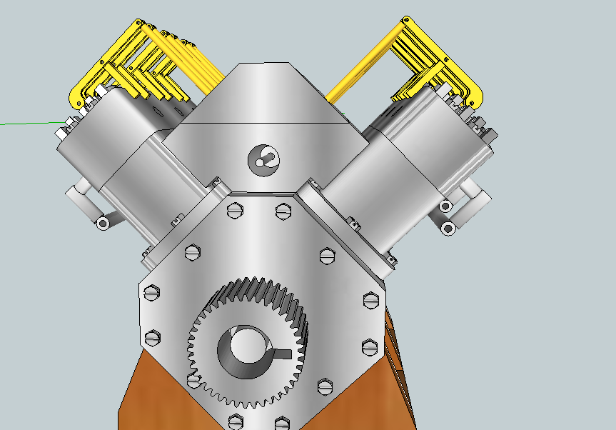
I'm thinking of making my own IC engine. Since I wanted to be different, having not seen many 90 degree V6's on this site, I chose the V6.
I have most of the 3D Model of the engine complete.
I believe the only missing parts are: Timing Gears (more on that later), carburetor, Proper spark plug timings.
Check out these photos:
Over Head Cam Model
Over Head Cam Model 2
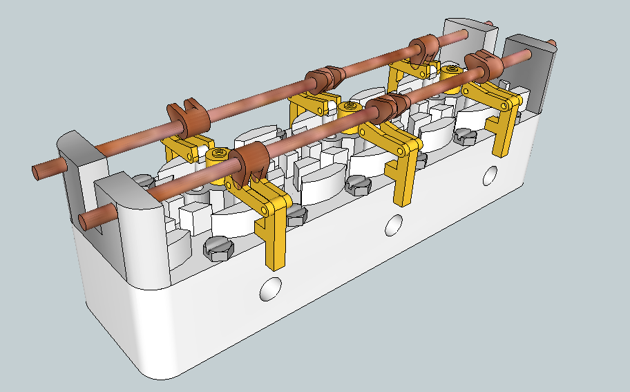
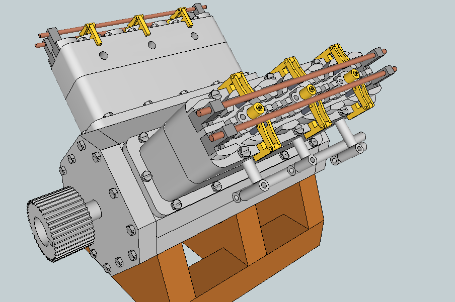
Over Head Valve Model
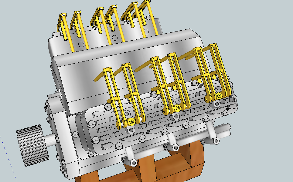
Over Head Valve Model View 2
Those white pipes are the exhaust headers; just a quick drawing on that part.
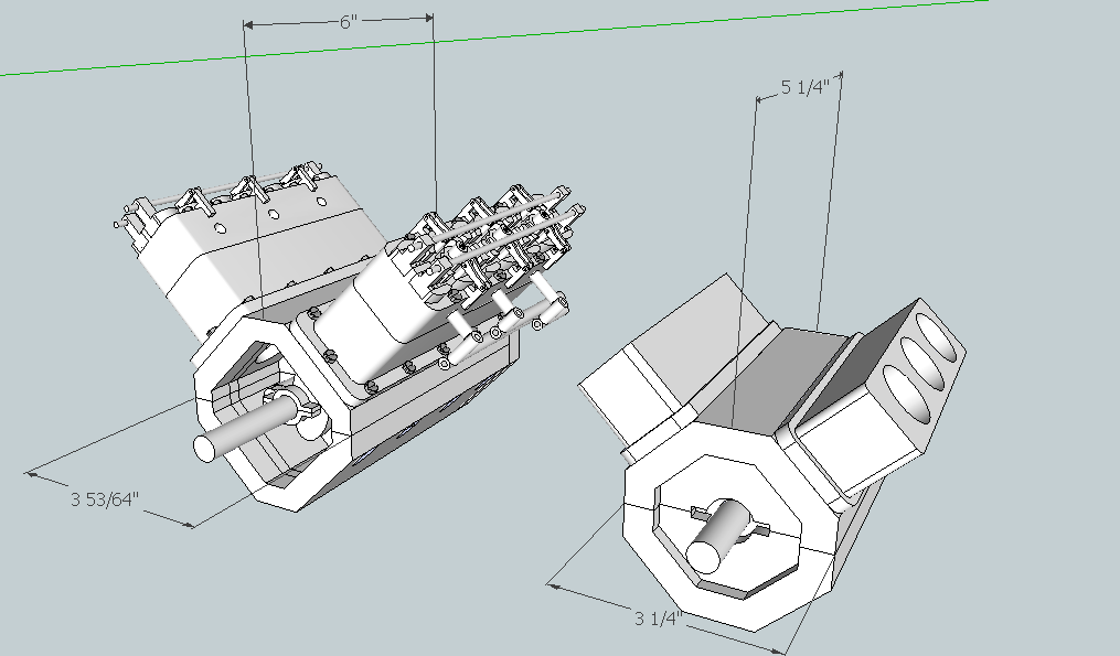
The engine dimensions are as such:
Case: 3 53/64"Width X 3 53/64"Hieght X 6"Length(excluding the 1/2" thick end caps)
I feel that the way the case is shaped provides a built in oil pan.
Pistons: Length: 3/4"
Diameter: 1"
Stroke(travel in the cylinder): 1 11/32" difference
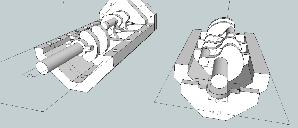
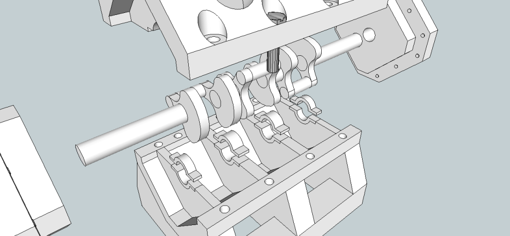
Crankshaft: Largest Diameter (the used rod would be 1 5/8" Diamter)
Piston Arms: 2 1/2" total length
I am wondering if this engine has any potential in running, with some changes ofcourse.
Also, i am looking for advice on how the timing works for this type of engine. Answers such as the ratio between the gear on the crankshaft to the cam rods would be extremely helpful. I will also be greatful for some web links to pages containing such information that i can learn from.
As you can see in the above photos, i have two versions of the possible valve systems. One is with DOHC (Double Over Head Cam) and the other OHV (Over Head Valves). I'm not sure which version to choose from, but the OHV version seems like it would be easier to make once i find out the gear ratios.
I am very new to machining, i dont have a lathe or milling machine yet (planning on getting the lathe this weekend). You might have seen the Elbow engine that i made a while back. I'll redo the cylinder blocks and complete it once i get the lathe before i start working on this engine. I know that this is a HUGE step forwards from a simple looking 12 piece elbow engine, but once i get my mind on a project, i dont stop thinking about it until something new comes along.
Thanks,
Ian
Here are some more photos:
Exploded 1
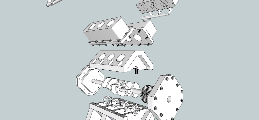
Exploded 2
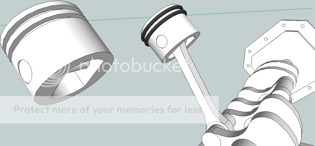
Piston
I've been roaming this site for a while now; looking at people's amazing engines. I've spent alot of time going over kcmillin's Tiny Inline 4 Cylinder IC Engine, keith5700's 1/4 scale V8 Engine, and stevehuckss396's Small V8 Engine.
I'm thinking of making my own IC engine. Since I wanted to be different, having not seen many 90 degree V6's on this site, I chose the V6.
I have most of the 3D Model of the engine complete.
I believe the only missing parts are: Timing Gears (more on that later), carburetor, Proper spark plug timings.
Check out these photos:
Over Head Cam Model
Over Head Cam Model 2
Over Head Valve Model
Over Head Valve Model View 2
Those white pipes are the exhaust headers; just a quick drawing on that part.
The engine dimensions are as such:
Case: 3 53/64"Width X 3 53/64"Hieght X 6"Length(excluding the 1/2" thick end caps)
I feel that the way the case is shaped provides a built in oil pan.
Pistons: Length: 3/4"
Diameter: 1"
Stroke(travel in the cylinder): 1 11/32" difference
Crankshaft: Largest Diameter (the used rod would be 1 5/8" Diamter)
Piston Arms: 2 1/2" total length
I am wondering if this engine has any potential in running, with some changes ofcourse.
Also, i am looking for advice on how the timing works for this type of engine. Answers such as the ratio between the gear on the crankshaft to the cam rods would be extremely helpful. I will also be greatful for some web links to pages containing such information that i can learn from.
As you can see in the above photos, i have two versions of the possible valve systems. One is with DOHC (Double Over Head Cam) and the other OHV (Over Head Valves). I'm not sure which version to choose from, but the OHV version seems like it would be easier to make once i find out the gear ratios.
I am very new to machining, i dont have a lathe or milling machine yet (planning on getting the lathe this weekend). You might have seen the Elbow engine that i made a while back. I'll redo the cylinder blocks and complete it once i get the lathe before i start working on this engine. I know that this is a HUGE step forwards from a simple looking 12 piece elbow engine, but once i get my mind on a project, i dont stop thinking about it until something new comes along.
Thanks,
Ian
Here are some more photos:
Exploded 1
Exploded 2
Piston