Joachim Steinke
Active Member
- Joined
- Jun 14, 2010
- Messages
- 29
- Reaction score
- 22
Hi
As the topic compound rest mounted grinders is discussed in the question and answers section at the moment I want to show you my answer to this affair. Some of you will have seen one of the grinding spindles on my already displayed cam grinder as well.
My first attempts at grinding on the lathe had also been with a Dremel like Proxxon miniature grinder which I had placed in a clamping fist on my tool post. But naturally the results turned out more or less disappointing, even after dressing the small grinding pens I had to fight with chatter and the surfaces where mainly rough and uneven. There is simply too little rigidity in the whole spindle bearings, okay, this small handheld grinders are not constructed for that purpose anyway.
So I had to look for another solution ..
For a better understanding of my approach to this (and other) self made tooling I have to remind you that I only have small machines and Im building more or less tiny things with this equipment. So many of my self-constructed items have to fit (and work!) properly in this limited space, and that often leads to dimensions of nearly the size of watchmaker machinery.
People with full grown lathes can simply by a commercial tool post grinder, there is a wide range of offers from cheap to expensive ones with more ore less quality. But the commercial ones dont fit on my PD360 in any way. Even if Im able to mount them, there will be no chance to move around sufficient enough in all the limited areas, not to mention the heavy load on the small lathe support.
A still matching design could be borrowed from the traditional watchmaker milling- and grinding auxiliary spindles, but I dont want to have a transmission above and beside the lathe. I wanted a small and compact but mostly efficient system which is carrying its own drive train. And I wanted the opportunity to carry out light milling jobs with the same equipment on demand.
So I turned on the CAD station and tried to design something that will fit my needs. And as a really small spindle is more convenient for fine jobs, otherwise a more powerful spindle is needed for some bigger tasks, I decided to build two versions.
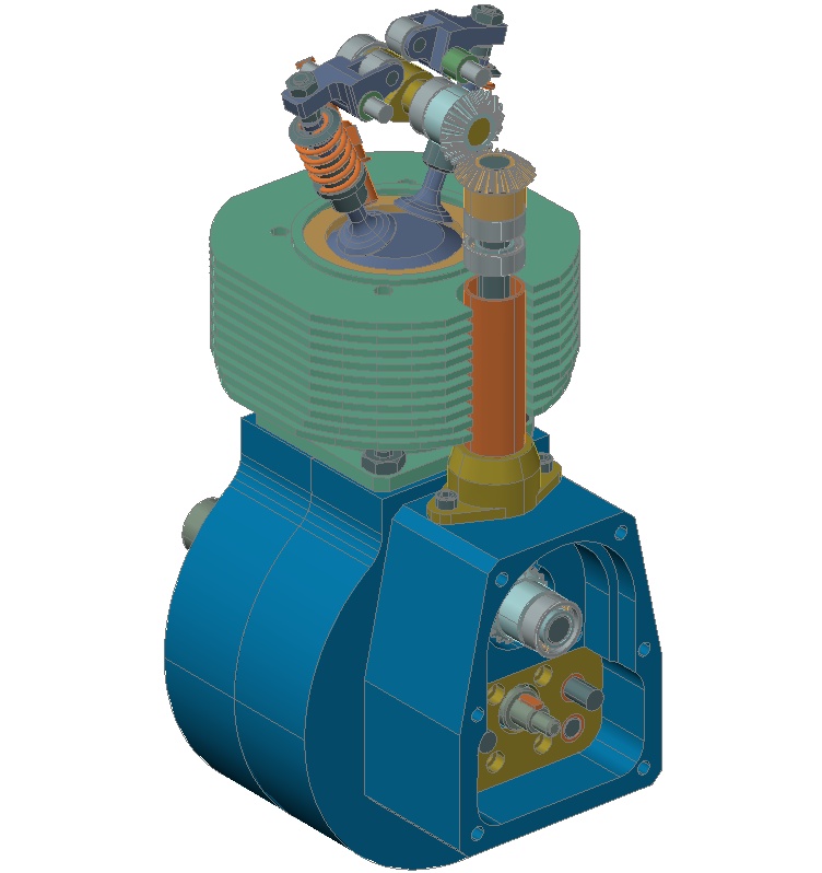
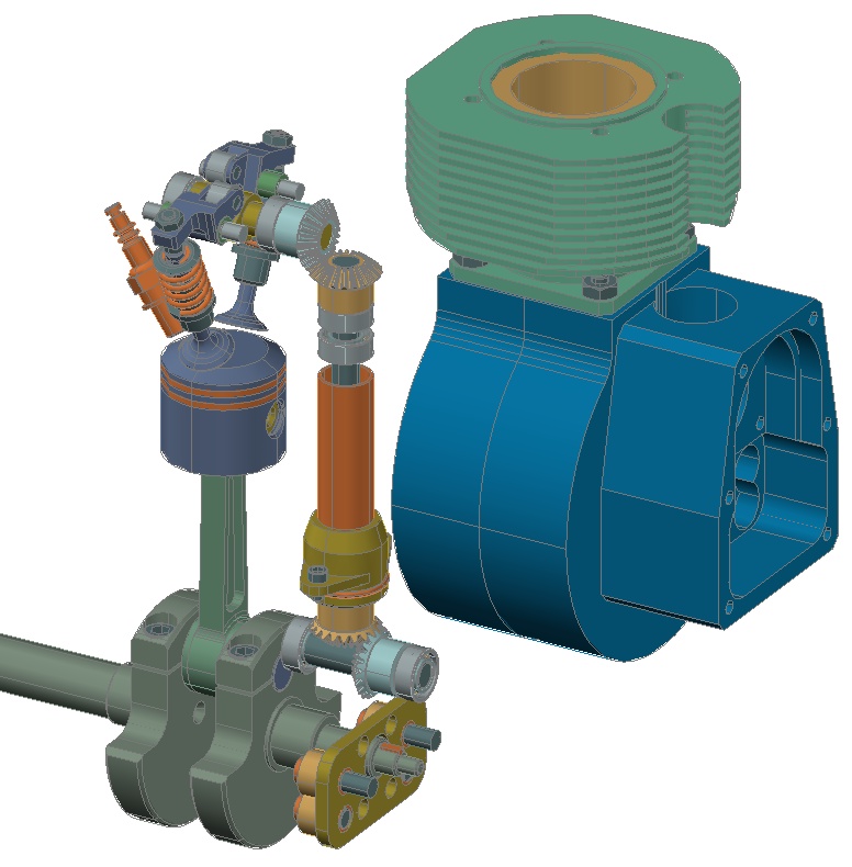
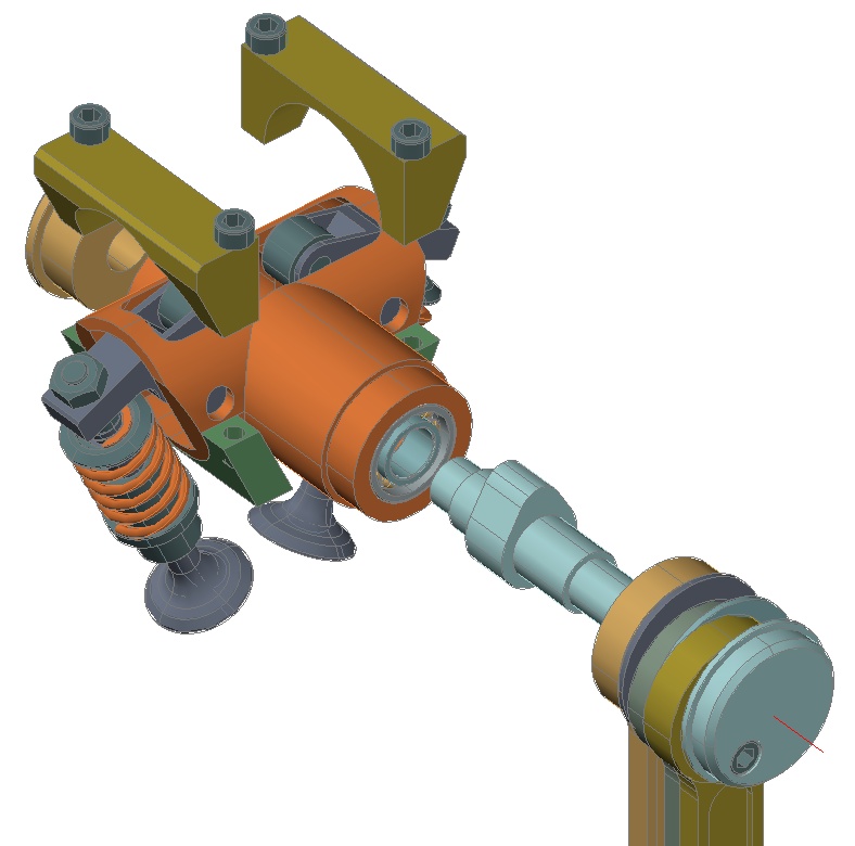
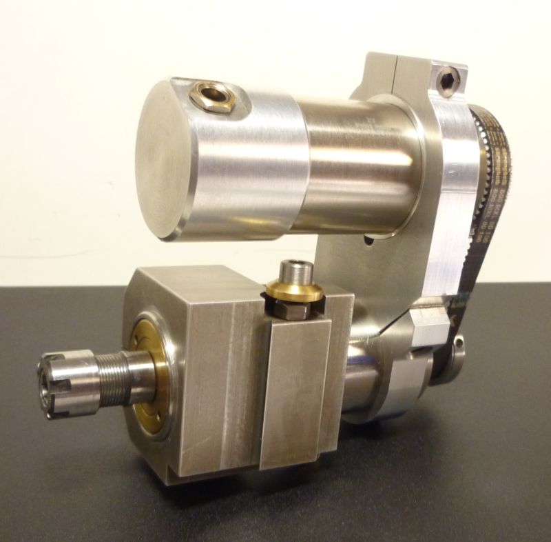
This is the small one:
I established a diameter of 33mm for all my spindle housings, which fits barely in my machine dimensions but offers enough space for suitable bearings. For this spindle shaft I took a commercial ER11 collets shaft of 12mm diameter, the bearings are normal ball bearing types which get a small axial preload when assembling the rear drive pulley.
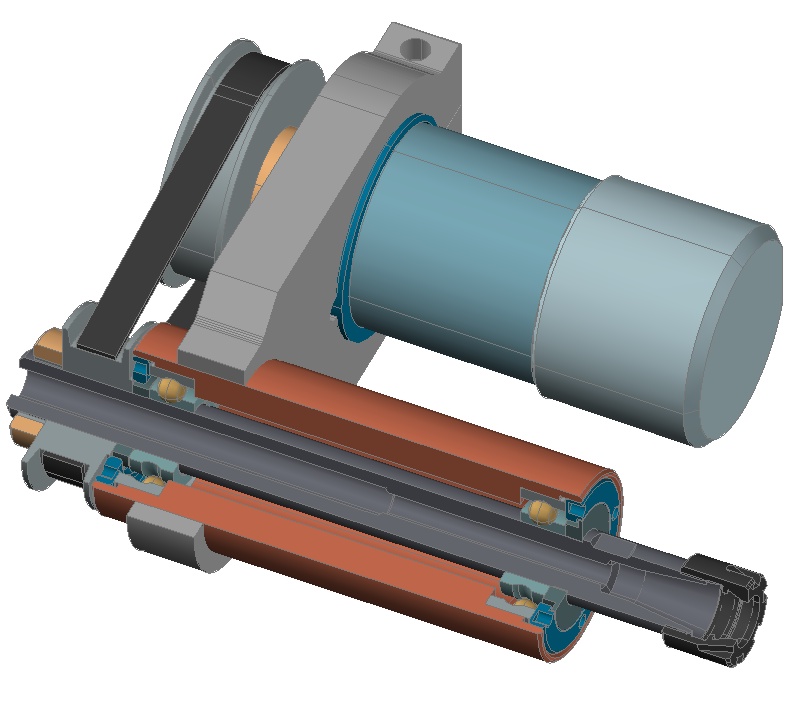
Powering comes from a 32V/75VA Escap DC motor which is driven by an adjustable power supply. For tensing the MXL tooth belt the motor got an eccentric mounting ring, so the pulley distance can be varied turning the whole unit in its clamping fist easily, thats what you see on the drawing here:
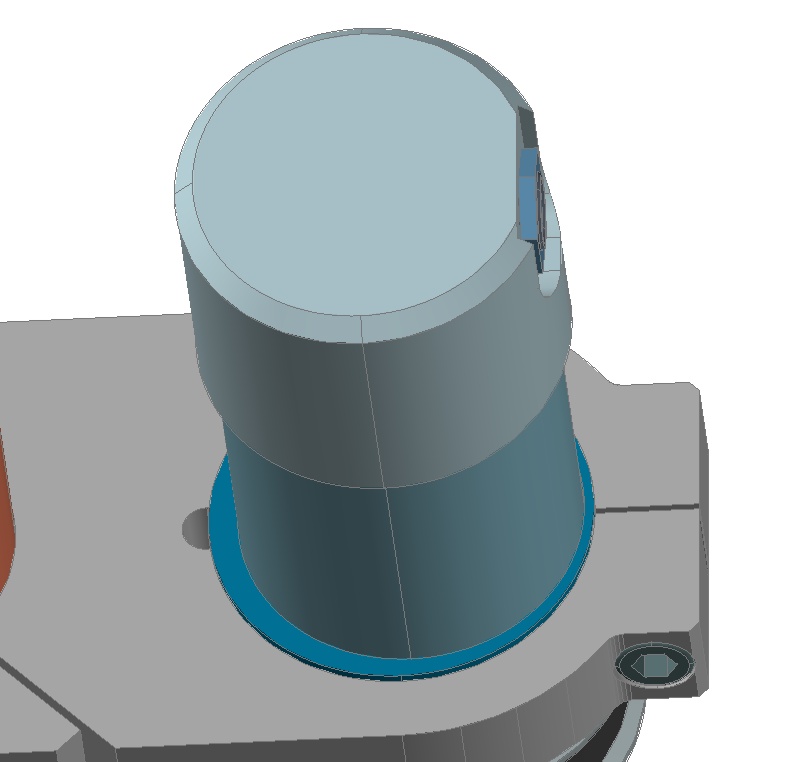
The pulley train creates a drive ratio of 2:1 which enables a maximum spindle speed of 12thousand rpm. As I said, that is a small but very handy system for jobs like inner grinding jobs and also tiny carbide millers of no more than 2 ore 3mm diameter. This spindle runs very quite and without any vibrations, apartment sessions at midnight will not bother the sleeping neighbourhood ha ha ha .
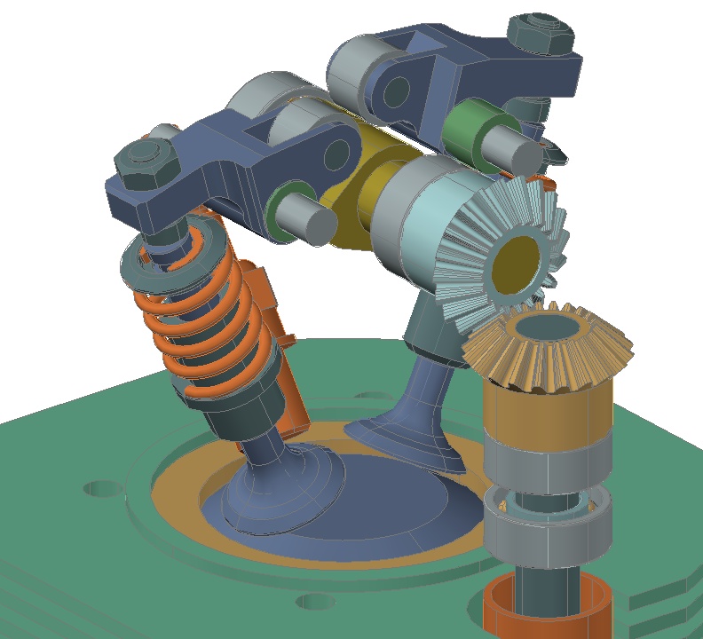
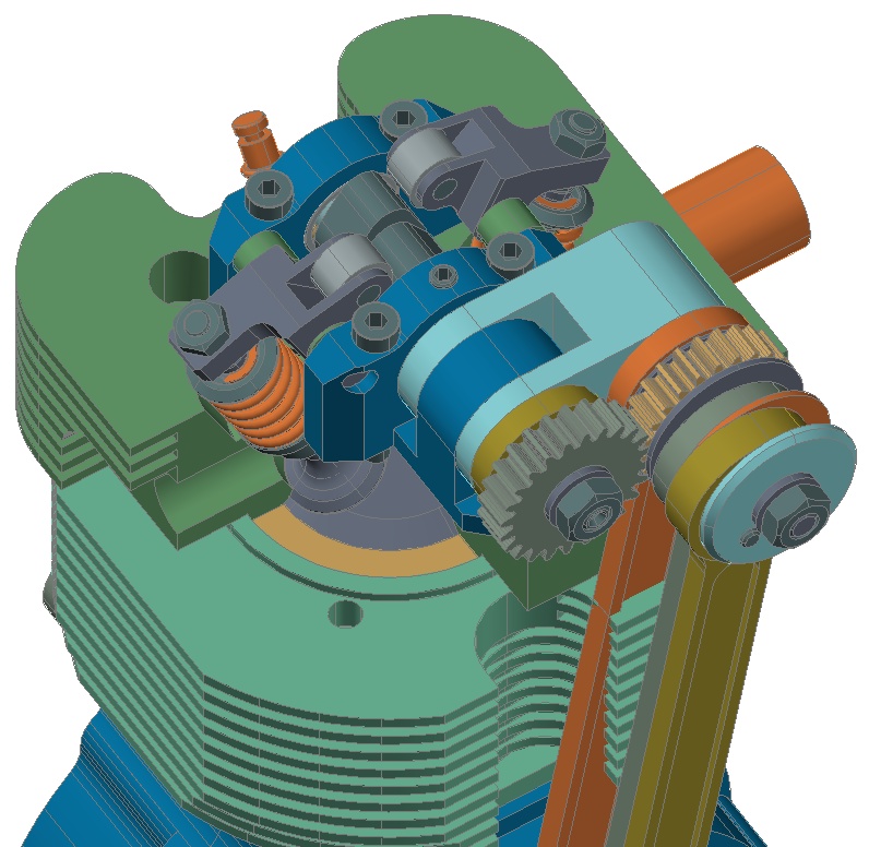
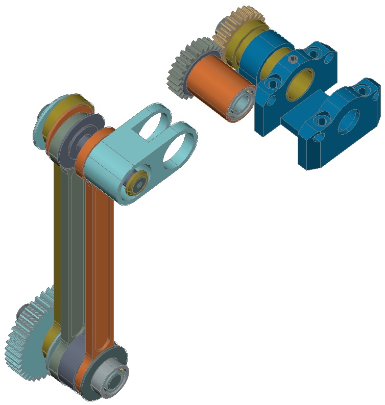
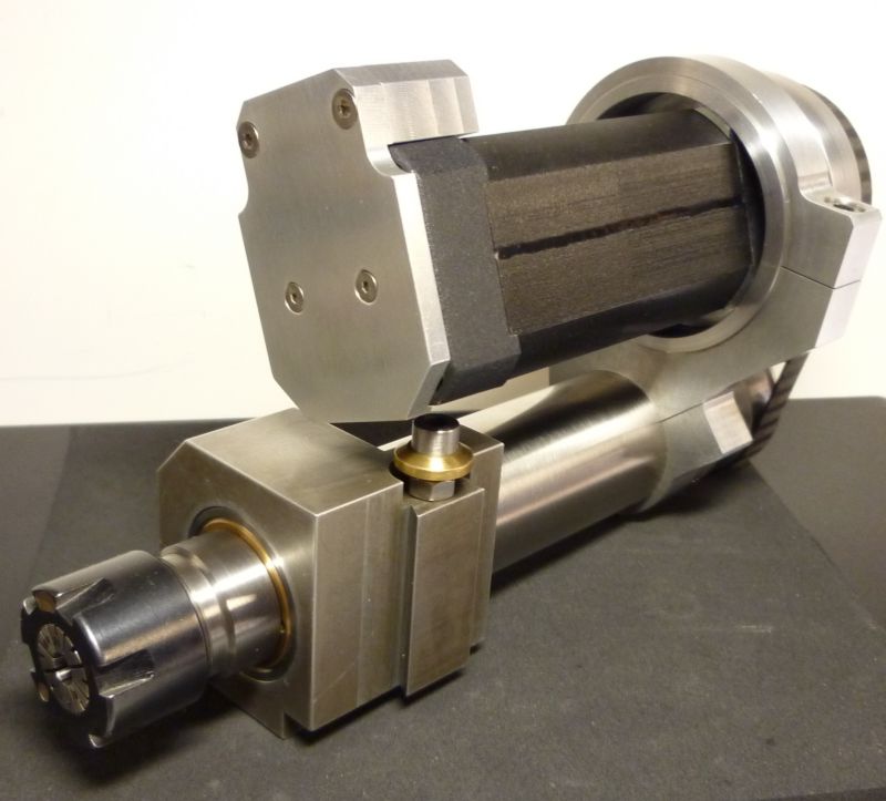
The design of the bigger version proved to be a little more complicated. I intended to get something about 150VA in the power unit and sufficient rigidity in the spindle bearings. Two angular contact ball bearings will be the first choice for this job. But the smallest ones are 30mm in outer diameter (my spindle housing has only 33mm) and they will have a bore of 10mm, no way to build a sense making spindle with this diameter.
In addition I wanted a collets system for the tooling interface and a hollow shaft with minimal 12.5mm inner bore. So I decided to take two double row angular contact ball bearings, FAG 3803 (17/26/7). What is clearly a compromise as they can not take the same load than the bigger (one row) 7202 types, but it will work for my duty.
The bearings get their needed preload from a saucer spring supported by the belt pulley.
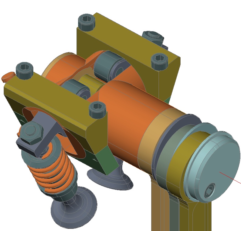
The hollow shaft is made from high carbon steel and got an ER20 interface with a tread for mini type collets nuts.
The collet system is highly universal and allows a wide range of tooling use, but it is no perfect support for larger grinding wheels. For that reason I designed an adaptor which uses the ER cone as a tool seat. The adaptors are made for grinding wheels with a standard inner bore of 20mm (solid corundum and compound dia/cbn wheels as well) and are fixed with a draw bar. The adaptors are much like the short cone SK25 tooling shafts we like to use on professional millers here in Germany, they offer high rigidity, a precise run out and some real fast wheel change.
Okay, that was done quite suiting until here, but how to get some serious 150VA of motor in my small dimensions?
Im absolutely no fan of noisy machines, so normally brushed DC motors are no choice for me. But I didnt want to disturb the whole neat design with a 3 phase motor of nearly 4 pounds weight which in addition will become as big as a drum (compared to the rest) ha ha ha.
So I gave a different motor concept a chance, a brushless direct current servo motor, they have half the size of a comparable induction motor. But they wont run on a normal power supply, you need a special amplifier that synthesises 3 rotating phases of direct current.
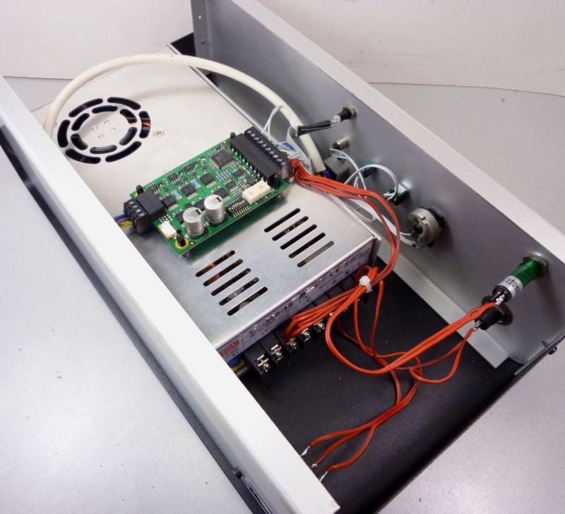
Finally I ordered a DECS 50/5 1-Q-EC amplifier from Maxon. With this controller the servo motor can by driven in a wide speed range and nearly full motor torque is available from about 800rpm up to full speed.
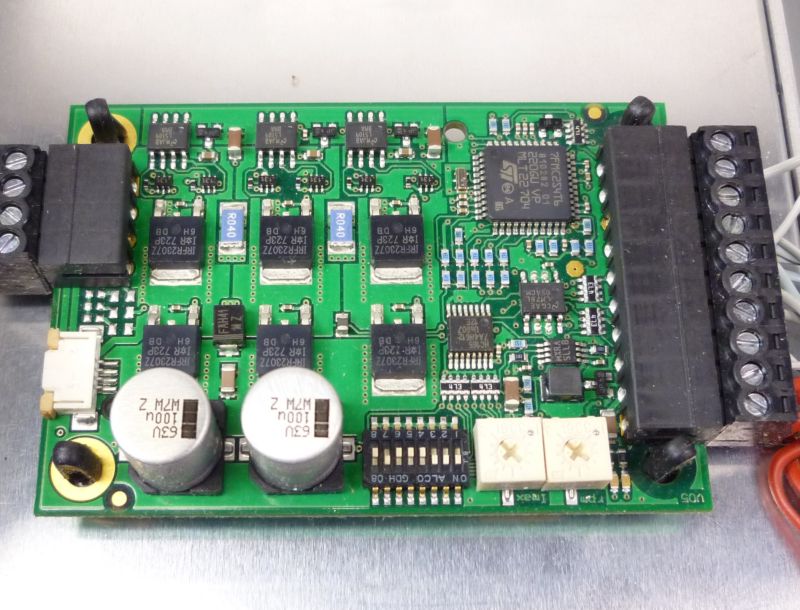
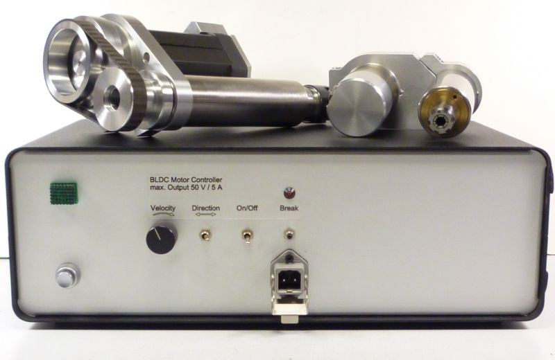
And installed it together with a 48V/7A switching power supply in a housing.
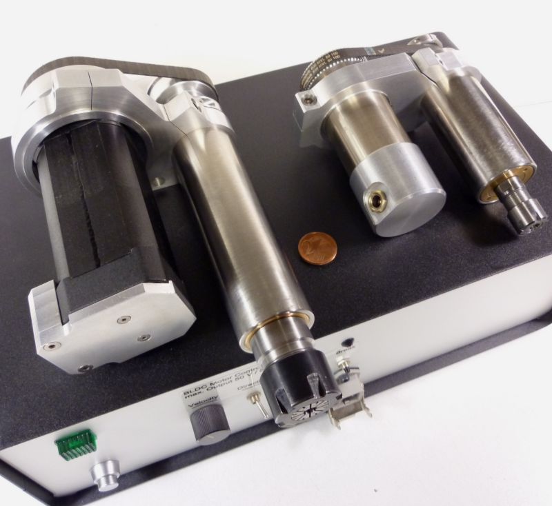
Oops ..someone must have finished the two grinding/milling spindles in the mean time as well ..ha ha ha .
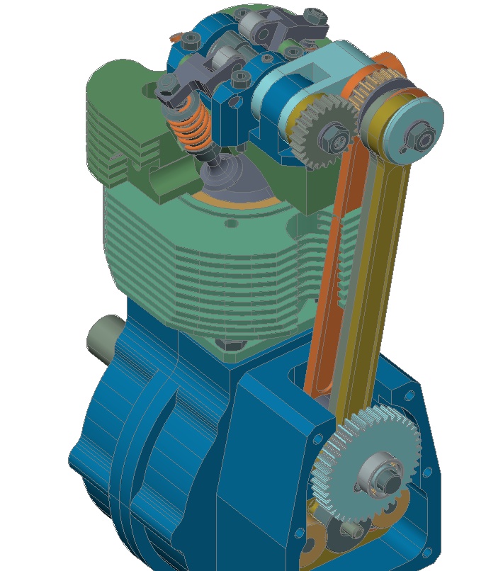
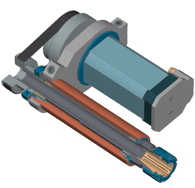
The BLDC Motor comes from Nanotec, a DB42C01 type, only 42x42x100mm and 0.75kg, 48V/150VA, 6000 rpm max. speed range.
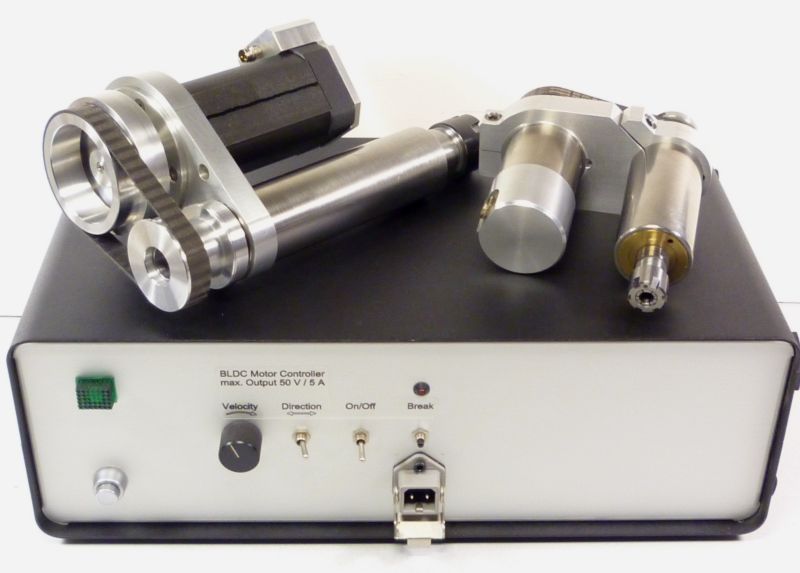
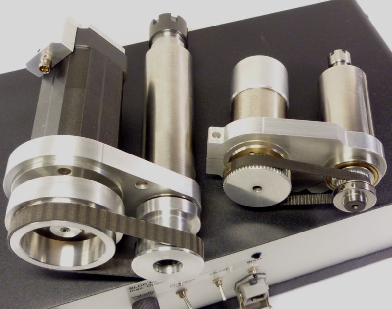
The drive train is realized with a flat belt, which provides a smooth running without any vibrations at high speed. The pulley combination can be altered easily from 1.4:1 to 2.4:1 by using the similar eccentric motor mount system than I had build for the smaller spindle.
As the servo motor goes with this Maxon controller up to 7000rpm (more than the 6000rpm from Nanotecs data sheet), the pulley combination enables maximum speeds of 10tousend and 17thousand rpm. That gives enough speed for all inner grinding jobs with small grinding pens as well. And the system is real quite too, only a small swoosh to hear.
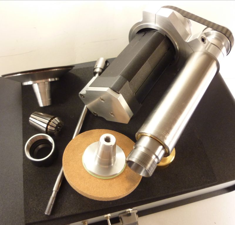
And here the short cone adapters for use instead of the ER collet system.
To install the spindles in the lathe I made a special cartridge for my tool changer system, so changing goes real quick and the mounting is as near as possible to the other components. That provides rigidity and saves space.
As I generalized the outer diameter of my spindle liners both spindles will fit in all adapters I made for several purposes and for use on several machines.
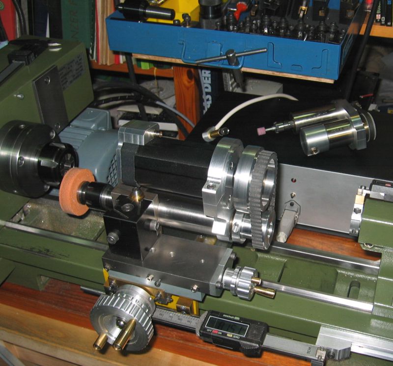
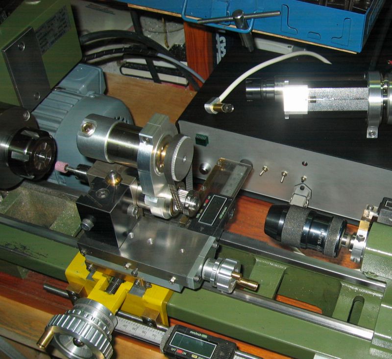
At last here some pictures of the spindles positioned on the lathe.
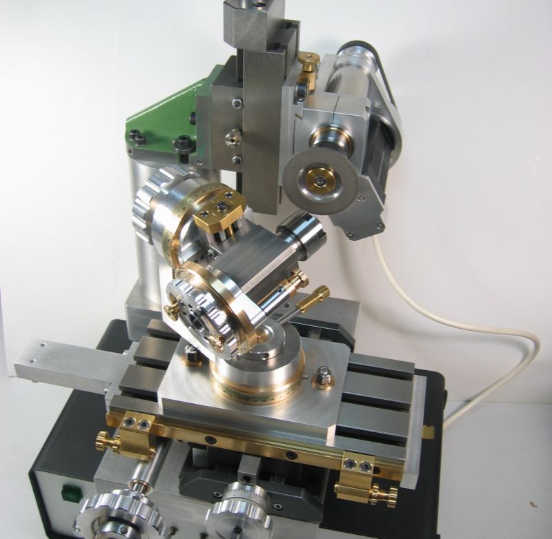
And naturally I use both of them (mainly the bigger one) on my universal tool grinder as well now.
In the mean time both spindles had made a lot of jobs, inner cones for self made collet systems, some outer round grinding and small drilling and milling tasks on parts that could stay directly in the lathe chuck etc. etc .. and the complete work on the tool grinder.
The components proved to be very reliable and the whole concept is really convenient to me, lets say, I dont want to miss this little helpers anymore.
Achim
As the topic compound rest mounted grinders is discussed in the question and answers section at the moment I want to show you my answer to this affair. Some of you will have seen one of the grinding spindles on my already displayed cam grinder as well.
My first attempts at grinding on the lathe had also been with a Dremel like Proxxon miniature grinder which I had placed in a clamping fist on my tool post. But naturally the results turned out more or less disappointing, even after dressing the small grinding pens I had to fight with chatter and the surfaces where mainly rough and uneven. There is simply too little rigidity in the whole spindle bearings, okay, this small handheld grinders are not constructed for that purpose anyway.
So I had to look for another solution ..
For a better understanding of my approach to this (and other) self made tooling I have to remind you that I only have small machines and Im building more or less tiny things with this equipment. So many of my self-constructed items have to fit (and work!) properly in this limited space, and that often leads to dimensions of nearly the size of watchmaker machinery.
People with full grown lathes can simply by a commercial tool post grinder, there is a wide range of offers from cheap to expensive ones with more ore less quality. But the commercial ones dont fit on my PD360 in any way. Even if Im able to mount them, there will be no chance to move around sufficient enough in all the limited areas, not to mention the heavy load on the small lathe support.
A still matching design could be borrowed from the traditional watchmaker milling- and grinding auxiliary spindles, but I dont want to have a transmission above and beside the lathe. I wanted a small and compact but mostly efficient system which is carrying its own drive train. And I wanted the opportunity to carry out light milling jobs with the same equipment on demand.
So I turned on the CAD station and tried to design something that will fit my needs. And as a really small spindle is more convenient for fine jobs, otherwise a more powerful spindle is needed for some bigger tasks, I decided to build two versions.
This is the small one:
I established a diameter of 33mm for all my spindle housings, which fits barely in my machine dimensions but offers enough space for suitable bearings. For this spindle shaft I took a commercial ER11 collets shaft of 12mm diameter, the bearings are normal ball bearing types which get a small axial preload when assembling the rear drive pulley.
Powering comes from a 32V/75VA Escap DC motor which is driven by an adjustable power supply. For tensing the MXL tooth belt the motor got an eccentric mounting ring, so the pulley distance can be varied turning the whole unit in its clamping fist easily, thats what you see on the drawing here:
The pulley train creates a drive ratio of 2:1 which enables a maximum spindle speed of 12thousand rpm. As I said, that is a small but very handy system for jobs like inner grinding jobs and also tiny carbide millers of no more than 2 ore 3mm diameter. This spindle runs very quite and without any vibrations, apartment sessions at midnight will not bother the sleeping neighbourhood ha ha ha .
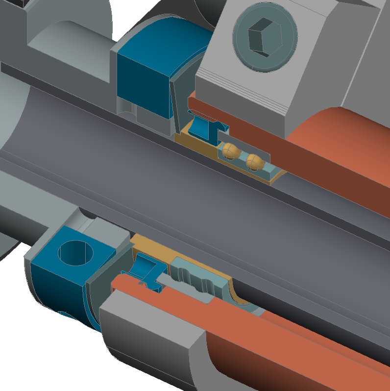
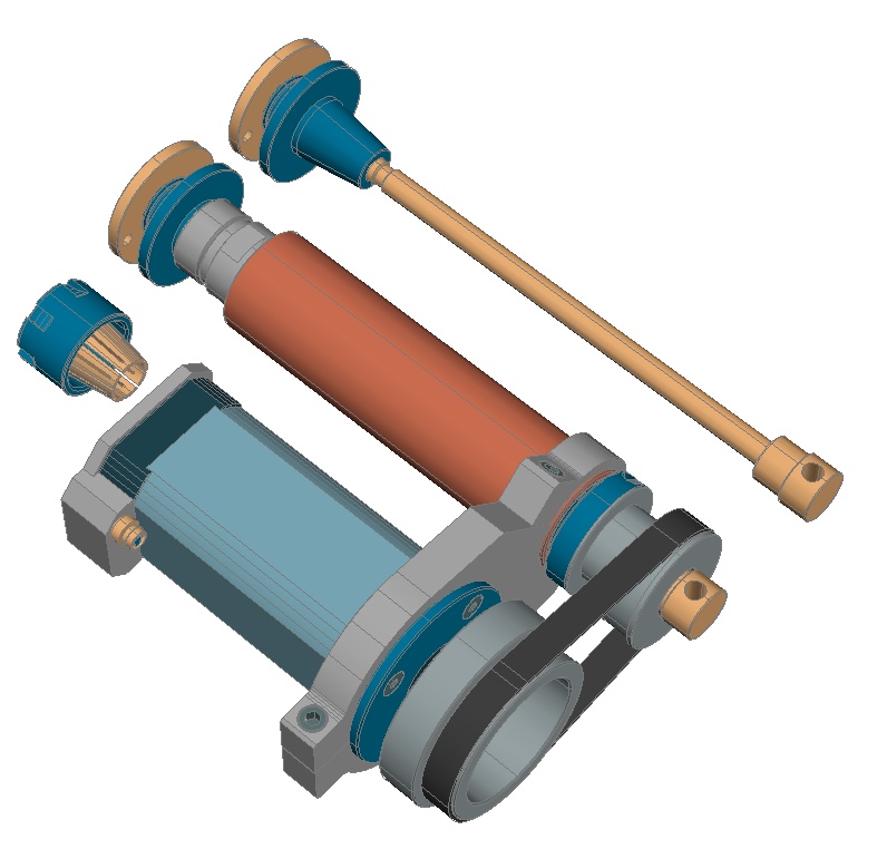
The design of the bigger version proved to be a little more complicated. I intended to get something about 150VA in the power unit and sufficient rigidity in the spindle bearings. Two angular contact ball bearings will be the first choice for this job. But the smallest ones are 30mm in outer diameter (my spindle housing has only 33mm) and they will have a bore of 10mm, no way to build a sense making spindle with this diameter.
In addition I wanted a collets system for the tooling interface and a hollow shaft with minimal 12.5mm inner bore. So I decided to take two double row angular contact ball bearings, FAG 3803 (17/26/7). What is clearly a compromise as they can not take the same load than the bigger (one row) 7202 types, but it will work for my duty.
The bearings get their needed preload from a saucer spring supported by the belt pulley.
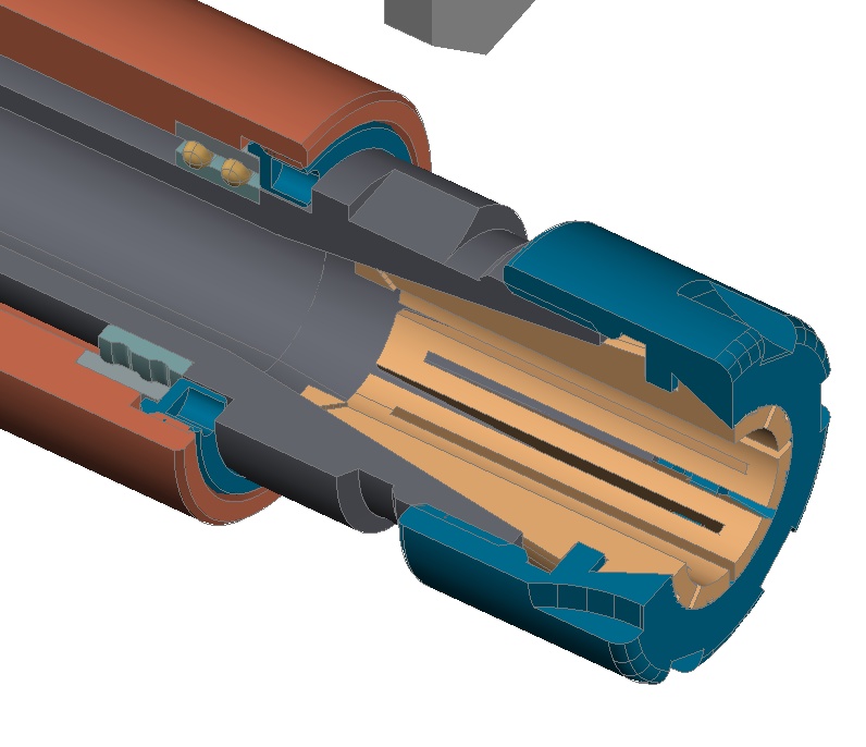
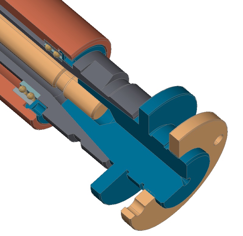
The hollow shaft is made from high carbon steel and got an ER20 interface with a tread for mini type collets nuts.
The collet system is highly universal and allows a wide range of tooling use, but it is no perfect support for larger grinding wheels. For that reason I designed an adaptor which uses the ER cone as a tool seat. The adaptors are made for grinding wheels with a standard inner bore of 20mm (solid corundum and compound dia/cbn wheels as well) and are fixed with a draw bar. The adaptors are much like the short cone SK25 tooling shafts we like to use on professional millers here in Germany, they offer high rigidity, a precise run out and some real fast wheel change.
Okay, that was done quite suiting until here, but how to get some serious 150VA of motor in my small dimensions?
Im absolutely no fan of noisy machines, so normally brushed DC motors are no choice for me. But I didnt want to disturb the whole neat design with a 3 phase motor of nearly 4 pounds weight which in addition will become as big as a drum (compared to the rest) ha ha ha.
So I gave a different motor concept a chance, a brushless direct current servo motor, they have half the size of a comparable induction motor. But they wont run on a normal power supply, you need a special amplifier that synthesises 3 rotating phases of direct current.
Finally I ordered a DECS 50/5 1-Q-EC amplifier from Maxon. With this controller the servo motor can by driven in a wide speed range and nearly full motor torque is available from about 800rpm up to full speed.
And installed it together with a 48V/7A switching power supply in a housing.
Oops ..someone must have finished the two grinding/milling spindles in the mean time as well ..ha ha ha .
The BLDC Motor comes from Nanotec, a DB42C01 type, only 42x42x100mm and 0.75kg, 48V/150VA, 6000 rpm max. speed range.
The drive train is realized with a flat belt, which provides a smooth running without any vibrations at high speed. The pulley combination can be altered easily from 1.4:1 to 2.4:1 by using the similar eccentric motor mount system than I had build for the smaller spindle.
As the servo motor goes with this Maxon controller up to 7000rpm (more than the 6000rpm from Nanotecs data sheet), the pulley combination enables maximum speeds of 10tousend and 17thousand rpm. That gives enough speed for all inner grinding jobs with small grinding pens as well. And the system is real quite too, only a small swoosh to hear.
And here the short cone adapters for use instead of the ER collet system.
To install the spindles in the lathe I made a special cartridge for my tool changer system, so changing goes real quick and the mounting is as near as possible to the other components. That provides rigidity and saves space.
As I generalized the outer diameter of my spindle liners both spindles will fit in all adapters I made for several purposes and for use on several machines.
At last here some pictures of the spindles positioned on the lathe.
And naturally I use both of them (mainly the bigger one) on my universal tool grinder as well now.
In the mean time both spindles had made a lot of jobs, inner cones for self made collet systems, some outer round grinding and small drilling and milling tasks on parts that could stay directly in the lathe chuck etc. etc .. and the complete work on the tool grinder.
The components proved to be very reliable and the whole concept is really convenient to me, lets say, I dont want to miss this little helpers anymore.
Achim
")