Turning down a motor spindle

Home Model Engine Machinist Forum

Help Support Home Model Engine Machinist Forum:

This site may earn a commission from merchant affiliate links, including eBay, Amazon, and others.

JimM

Well-Known Member
Joined
Jan 6, 2009
Messages
170
Reaction score
0
I'm trying to convert my newly acquired milling machine to run on the electrics I have in my garage. Plan is to run the horizontal head/table feed from a single phase motor and leave the vertical head as 3 phase and run this from an inverter for the variable speed facility.

I have a single phase motor of the right size but the spindle is too big for the step pulley. Boring out the pulley isn't really on option so I'm hoping to be turn down the spindle from 24mm to 20mm but have a few questions

1. I've never taken a motor apart but I'm guessing the spindle is integral to the motor and not something I can remove to put in the lathe chuck ?

2. Assuming the above to be correct, I thought I might clamp the entire motor to the lathe bed and use the motor itself to turn the spindle. Motor speed is 1425rpm is this going to be too fast to work in practice.

3. The spindle has a keyway, if I limit my DOC to 0.005" will this overcome the problem of interrupted cut

4. Any better suggestions always welcome (before anybody says it I have got my eye out for a suitable sized motor/spindle combo)

Thanks

Jim
 
[1] Spindle is integral to the rotor which can be removed and put in the lathe, single phase motors often have a centrifugal switch mounted on the terminal end so you undo the bolts holding it after taking the cowling and fan off and see how it fits, you often have to take a couple of screws out to get it to come free.

Sorry can't be more explicit as all motors differ.

[2] You could take the fan off, stick that bit of the rotor in the chuck, support tother end in a centre and lash the body to the bed to stop it spinning, then turn it.
don't bolt it to the bed as you will have hells own they to get it parallel in two planes and on centre hight.

[3] Don't worry, just blast away, it's only the finish cuts that matter.

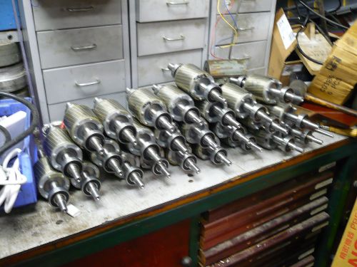
I have to do 30 motors a month, regular job from 28mm down to 24mm, first pass on all reduces them from 28 to 25 or so.
New tip and second cut takes them from 25mm to 24mm in one pass.

Also have to do some from 19mm down to 14mm, again just two passes.

rotors25.jpg


John S.
 
Hi John

Thanks for the useful info, got halfway to getting the rotor out but am stuck again. Front cover is off and that end of the rotor is loose, fan is off but the rotor will not slide out. There's a few screws that look likely suspects but don't want to undo anything and find that some small part is now irretrievably down the back of the motor :)

I've added a few pics, any suggestions on what I need to do to get the rotor out (was contemplating just giving it a whack with the hammer to see if that shifted it !)


IMG_2002.JPG


IMG_2003.JPG


IMG_2005.JPG
 
Just a guess on your problem. It is not uncommon for the out end bearing to be too large to go through the hole n the start switch. When you pull the rotor from the shaft end you hope the shaft comes out of the bearing in the out end bell. If the bearing comes out of the end bell stuck to the shaft you risk destroying the start switch.

You need to tap loose the end bell and see what is happening. It may be necessary to get in with short screwdrivers and take everything loose so that you can pull the bearing off the shaft. If the end bell has an exposed end of the shaft or a dust cap over the center hole you can use a drift to drive the shaft out of the end bell.

There is no problem to reduce the size of the shaft in the lathe but if it doesn't have a center hole you will have to set it up with a steady rest and and get an exact center to support the shaft when you turn it.
 
Give it a whack with a copper hammer to break the end shield away, carefully open it up to see how the switch if fitted is secured.

You will probably have to remove the two nuts in the second pic as they will hold a bearing retaing plate.
Usually these spin, then jam before undoing.
When you come to reassemble it becomes clear how the cam action works.

No idea what the plugs are in photo 3, don't think they are relevant.

John S.
 
John Stevenson said:
Give it a whack with a copper hammer to break the end shield away, carefully open it up to see how the switch if fitted is secured.

Not wishing to appear totally dense (although think that pretence has long gone ) but are you suggesting I hit the shaft or hit the outer casing to separate it from the main body

Thanks

Jim
 
Hi Jim, you probably will have to remove the two bearing retaining screws as John had suggested this is very common on electric motors, with the motor supported vertical on blocks give the shaft a wack with a copper hammer.
Hope this Helps Rob
 
Just to clarify, give the rotor end that's exposed ie, the one with the end cover removed a whack.
Not too hard you want to open the other end up so you can peer inside to see how the switch fastens.

Don't whack the end with the two screws even if they are undone at this point as you could drive the outer of the centrifugal switch, which is usually plastic over the switch contacts and smash something.

All this only applies to single phase motors as some have the switch, some don't, depends on design.

Three phase motors are real simple, same both ends, no switch, whack it either way .

John S.
 
OK, before giving you guys a chance to reply I attacked the motor again. Gave the end cover a couple of whacks to loosen it, then just pulled the rotor/shaft assembly out from the fan end. The assembley is bigger than I had envisaged but will fit on the lathe so I'll turn between centres tomorrow.

The switch is still attached as it sits between the rotor and end bearing and don't want to pull it apart unless I absolutely have to - any reason I can't do the lathe part with the swicth in place?

Thanks for all your help guys - learn something new every day from this site

Cheers

Jim
 
No, don't touch the switch, no need to bother about it, the only worry was some fixed switch plates are the wrong side of the rotor switch and pulling then out without checking can break either or both.

John S.
 
If the bearings are open ( no shields or seals ) you may want to cover them with something to keep the chip's out of them but don't use something loose that can get rapped up in the lathe or you. Cliff.
 
Cliff said:
If the bearings are open ( no shields or seals ) you may want to cover them with something to keep the chip's out of them but don't use something loose that can get rapped up in the lathe or you. Cliff.

Good point Cliff, I'll put some clingfilm (do you call it kitchen wrap in the US ?) round everything to keep the crud out.

Cheers
 
another good way to clean up afterwards... put a magnet inside a sandwich baggie and rub it around the surfaces and crevices. You'll be surprised how much metal dust will be found on a clean looking piece. Turn the baggie inside out and toss in the trash bin.


kermit
 
Back
Top