Team Design 1 - Cam Grinding Fixture

Home Model Engine Machinist Forum

Help Support Home Model Engine Machinist Forum:

This site may earn a commission from merchant affiliate links, including eBay, Amazon, and others.
Hi W/E,

The stationary follower would be above the master cam. The replicated cam would be ground against the vertical face of the grinding wheel. First blush would be to mount the cam grinding fixture on my baldor style import tool grinder located on the tilt table set into the mitre fence slot.

scan0001.jpg


The rig would be spring loaded against the master cam follower with an adjustment screw to allow for feeding the work in slowly.

Anybody out there?

Dave
 
Would it be better to have the master cam and cam stationary (well... they still rotate) and have the follower and grinding head pivot up and down? I'd imagine it would be easier to design and build.
 
We can add that concept to the pile. Sure why not.

I am still looking to create a spec. We should be discussing the differant design points.

Sorry....Designing something can be a lot of work :)

Dave
 
I agree on the need for specs. If we don't have a target, then how do we aim? :-\

Do we want to focus on a single design? Or two?
Do we want a fixture that would be usable with an existing bench grinder?
What size cams do we need to allow for?
On the master cam, do we want to use an inverted master lobe?
How do we control the master and blank rotation? Motor or by hand?
Do we use the wieght of the fixture to self feed, or do we use springs or weights?
What is the most narrow lobe we wish to cut without interfering with an adjacent lobe?

These are the questions that are rolling around in my head. Are there anymore to add to the mix?
 
Minimum width of the ground cam is critical. A bench grinder might be used here for a narrow cam but will need to be dressed accordingly. Alternatively, grinding on the perifory of the wheel would allow use of a dish wheel which are readily available.

Dave
 
Sorry I have been so long but I was looking for the sketch I made of the cam grinder, never did find it.
I was sure I scanned it in to send to someone but can't find a jpg anywhere on 2 hard drives.

I only have the one picture of the cam grinder as shown and unfortunatly it doesn't show the cam end.
So I did this tonight, very rough and it needs some explanation as some drive parts are not shown.
First the cam grinder again to save going back.

cam%20grinder.jpg


now the drawing.

cam%20grinder1.jpg


What is not shown is the drive from the motor to the inverse master cam which on the original was by two pairs of large pulleys just visible to get the speed of the blank down to about 100 rpm.

From the inverse cam there was a chain drive, again just visible to the spindle running at 1:1 to keep it all in time.

The radius of the follower has to be the same as the radius of the tappet, the master cam has to be the same diameter as the grinding wheel and the distance from the pivot shaft to the spindle has to be the same as the distance from the pivot shaft to the master cam shaft

I personally think the inverse master is an easier way to go as regards preparing as all you have to worry about is the sticky up portion of the cam.

 
Hi John! :)

Nice to hear from you. Tell me more about the inverse cam? Is there a mathmatical approuch to laying that out? That math should be part of the design in the end.

Is it easier to machine? I would appear to be a radius cut on a cylinder, and that is certainly simplier than a master cam, but I suspect there is other things going on there.

Warm Regards,

Dave :)
 
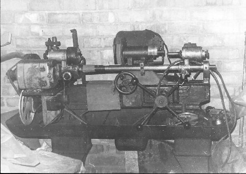
The master cam isn't as easy as just machining a radius into a cylinder although for some simple engines it wouldn't be far off, that's just my crappy drawing.

In the days when we were doing this, mid to late 1970's we had no CAD and it was all the hard way.

There were two methods we used, copy and development.
Copy was reasonable easy in that a known good cam was fitted up to the spindle, the master cam [ MC from now on ] was packed in or out and the follower replaced by a scriber.

Keeping the copy cam in contact with the wheel the whole lot was revolved one rev to scribe a mark on the MC which was then removed to be cut and filed into shape, we used alloy plate from 1/8" to 1/4" depending on what was to hand.

In the development method this was used where we had no cam or wanted to try a profile from another cam onto ours.
Many of the cams were welded up with Stellite and then reground to another shape.

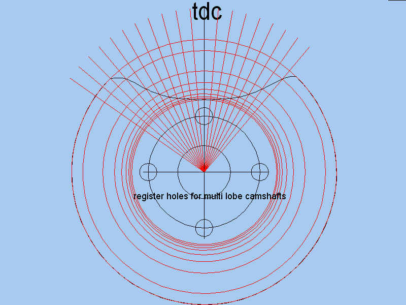
This was done by drawing a set of radial lines every 5 degrees and the opening and closing points marked.
Then diameters were laid off for lift at every 5 degrees and a line blended thru them. pic below:

This was the whole idea of working on larger master cams as it didn't get so cluttered and like a pantograph any errors were reduced by the scale factor.
If you are working on say a 6" wheel and the MC is 6" but you are grinding a 1/2" cam you are working at a 12:1 ratio
so any slight errors get canceled out 12:1

cam%20grinder2.jpg


This MC blank has to be laid out as a 6" cam, not a large cam with a small lobe, this way everything stays in scale and the same MC can be used on any size cam provided that the profile is what is needed.

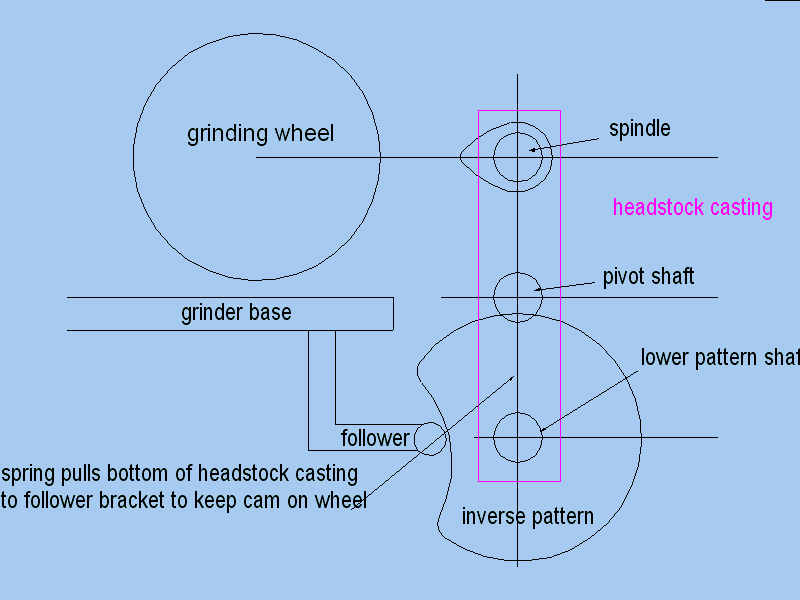
The cutout looks funny with it being the inverse but the data is exactly the same as if you drawn a proper cam and did the same as regards lines every 5 degrees and circles. You can even get the same data with a known cam and a degree plate and dial gauge.

The 4 central holes I missed out of the original drawing and these are so you can move the MC in relation to the camshaft being made so you can do multi cylinder engines.

Today with CAD and even CNC what we did years ago is a damn sight easier. The system does work, the original cam grinder did countless numbers of cams and the racing miles done by these engines must run into the tens of thousands given the average racing bike in the Isle of Man does about 1200 miles in race week including practice.

 
Hi John,

Ahhh! OK Understood.

How difficult do you think it would be to document the layout procedure for that inverse cam?
I think we are going to have to explain that to the average Joe.

I like the index being part of the master. That makes for a simple design.

12/1 is a great reduction ratio. Definitely makes the master less critical.

Sometime during the day today, I'll start putting the concepts and comments given into a spreadsheet to keep track and organize. Then maybe we can have a group poll as to what features are more important than others.

Maybe from there we can set a concept in firm oatmeal ;D

Dave
 
Dave, or anyone?
Do you have a drawing of a model cam with some form of data?
If so can you post it or links to it and I'll do a worked example.
.
 
Hi John,

I have several sets of plans for a few model engines. I am going to go through them because I want to look at diameter and width requirements. I have a few items on the "honeydo" and my kids soccer game today. Sometime later today. I will post the spread sheet with the max and min of these. That should cover most applications.

Dave
 
Hey all,

I was thinking about something more like this. I really like the idea of having the cam's stationary and the grinder head moving up and down (This model is just like a quick sketch, its not that great and it's not completely to scale. Also, haven't added the motor mount or drive belt so it's just floating there ::) )

Pic1.jpg


Pic2.jpg
 
This is a really nice thread, Thanks to all.

What kind of grinder would be floating up and down? Pneumatic?
 
Hi Jones, :)

Thanks for sharing that!
I understand. That is an inversion of the designs we have been talking about. As we are brainstorming, can you expound on your reasons of doing it that way? Does it make the unit easier to make or use fewer parts...or smaller parts....easier to set up....?

By the way...
When you brainstorm, it's pie in the sky, and there are no wrong or right answers. It's an exercise in creativity to get as many ideas down on paper as you can. :)

Critical and deliberate thought comes later after WE pick one idea to design and build.

Warm Regards,

Dave
 
I want to come up with a disign, I kind of have some ideas, but need to see a vid of one that some one has made, I will see if any ideas are on youtube :)
 
Hi Dave,

I just thought of this idea because it's the first thing I think of when I think 'cam grinder' or 'crankshaft grinder'. I think it might be a bit stronger this way, and less liable to twist than the moving camshaft design. I could be completely wrong, I've never built anything like this, but it seems that this one could be made easier to build.
However, I can see that with the original design proposed it would be easier to get the 12:1 reduction on the cams than on this design.

I found a pic of a cam grinder which has already been built which looks very similar to the model I made:
05gears07.jpg


Im interested to hear everyone's opinions on the two different designs, and new ideas.
 
Great Post Jones,

Now thats what WE are looking for....."heres what I think and why" Perfect!

It sure gets the juices going!

By the way, the base of that machine appears to be a table saw top. I think there was a right up in HSM on a cam grinder that used a table saw top.

The arm appears to be a miter saw arm maybe?

Thanks! Let's keep the thread and information flowing in. We can pick the best parts of it all and design our own.

Dave
 
Here's a thought regarding the picture that Jones has posted... Instead of having the master cam near the cam blank, why not have the master cam behind the pivot point? This would allow for altering the ratio between the master and blank more so than a design similar to this.

I like the stationary base and the rigidity it offers. The drawback I see to it is the weight and possibly the final size the machine would be. This might make it hard to work with in the HS environment, and storage of the unit will certainly need to be considered as well. Thoughts??

I really think that when we are done with this project, we will have the best design for a cam grinder suitable for use in the HS.
 
Hi W/E,

What the "back pivot" design that Jones published brings is the ability to swing the wheel up out of the way for inspection and measurement. Look how much room you have to get a set of mics in or even mount and indicator stand. I think a "monolithic" flat base has some advantages too from the perspective that it's easier to measure flatness, parallelism and run out from a qualified surface. However, I don't think we need one as big as a saw table.

Something maybe 12" x 18" would be about the right size. How about an import black granite surface plate?
Drill some holes and bond in some steel inserts with epoxy. It's done in industry all the time.
www.landis-us.com, www.nanotechsys.com, for instance.

......more for the pile of ideas ;D


Dave
 
I think we are getting some great thoughts here. Let's get a few more then hash out a set of specs. My thought is we aren't too far from deciding on a design and firing up the old 'puters.
 
Back
Top