Runner
Well-Known Member
- Joined
- Feb 10, 2011
- Messages
- 124
- Reaction score
- 17
Hi all,
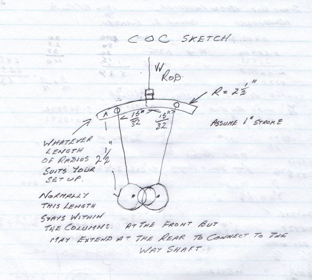
I am building a twin cylinder launch engine with Stephenson's reverse valve gear. It is of my own design, I haven't produced drawings, just made it up as I go. No castings are used, utilising stock material that I have to hand. The preconceived technical requirements that I have established for the launch engine is 1.375" stroke, 1.25" bore. In designing the valve gear I have decided upon a 0.1875 " offset on the eccentrics producing a 0.375" throw. The expansion link has a 0.8125" distance between the points where the eccentric rods connect and the curvature in the expansion link is 2.5" radius, to suit the length of the eccentric rods and straps that are also 2.5". I have completed it all except designing and producing the cylinders and steam chests, which will be made out of gunmetal which is going to be an expensive buy (relatively) so I am concerned that my version of Stephenson's valve gear is going to be a goer, before committing to the purchase of gunmetal for the cylinders and steam chests. My concern is that the expansion link rotates rather a lot, producing a steep angle to valve crosshead, making the valve cross head sit almost on the corners of expansion link, however it's the die that transmits the motion from the eccentrics to valve crosshead. This angle is controlled by the eccentric offset of 0.1875" and the distance between the the eccentric rods of 0.8125". This is rather difficult to explain and probably difficult to understand.
I expect that some leeway is available in designing versions of Stephenson's reverse valve gear, because I have seen pictures of many and they appear to be variations on a theme. However, there is probably an optimum solution. What is this? Will my design be suitable as is?
Thanks in advance.
Brian


