Steam Engine: Info Please

Home Model Engine Machinist Forum

Help Support Home Model Engine Machinist Forum:

This site may earn a commission from merchant affiliate links, including eBay, Amazon, and others.

roman

Member
Joined
Dec 27, 2010
Messages
7
Reaction score
0
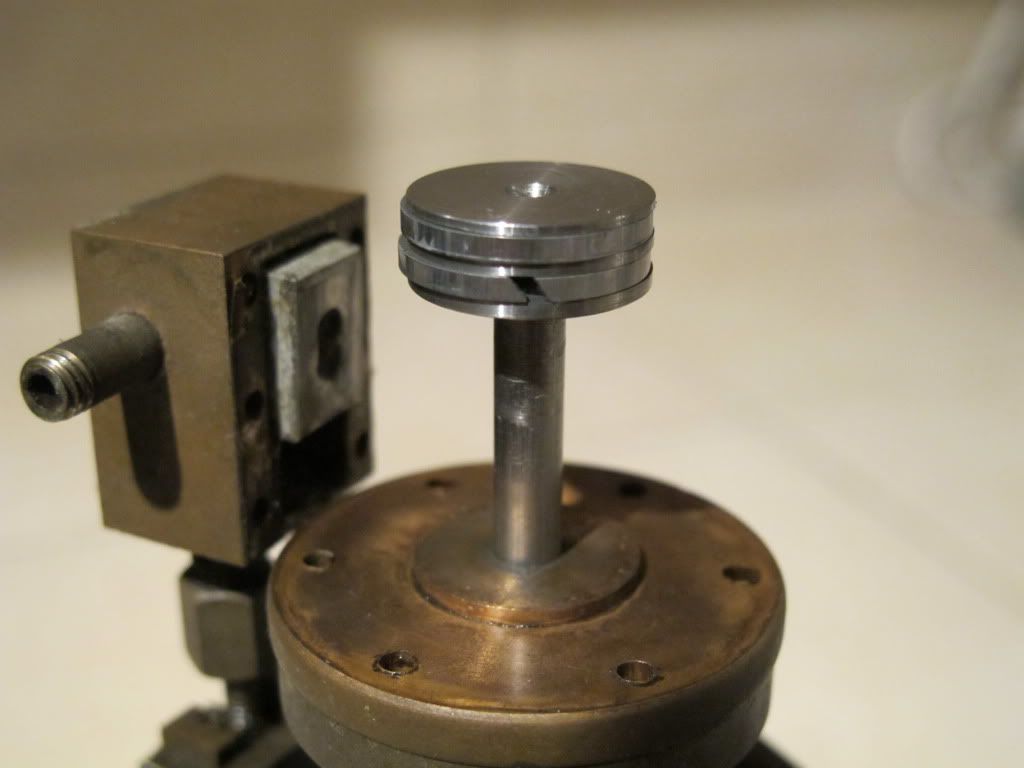
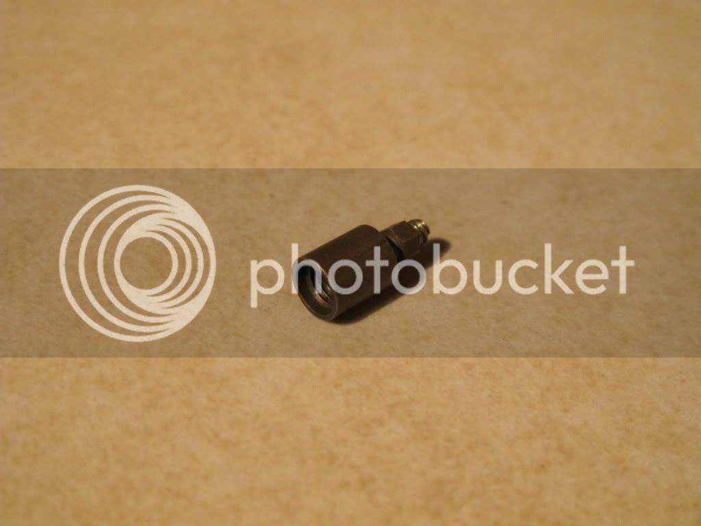
I received this steam engine as a gift for Christmas. I did not find any like this on the Internet. Total height with the stand is 8". I'm open to any information.

Here is a photo of it:

IMG_2499.jpg


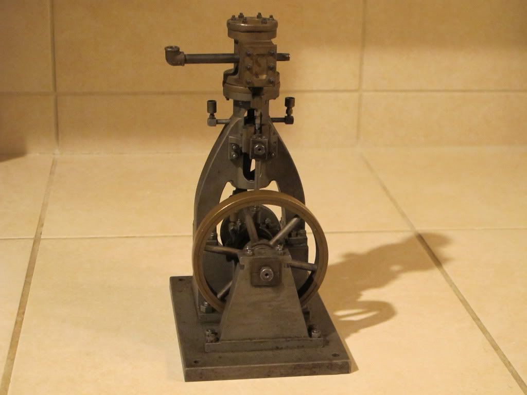
You can view more photos here:
http://s808.photobucket.com/albums/zz10/romyald/Steam engine/

Thank you everyone! Happy Holidays!
 
Welcome Roman.

I tend to disagree. It's a superbly built engine, but the location numbers stamped in various components makes me think it is the product of somebody's home work shop.
 
Pat J said:
Nice engine. What is the overall height?

Pat J

Thanks Pat J. The overall height is about 8 inches (20 cm.). The weight is 7 lb, 6. oz (3.34kg).
 
Another thought,

Could be a journeyman project for a fitter or engineer. They used to have to do that...

Dave
 
wow,

you have a good connection to santa (?) VERY COOL MACHINE could it posssibly be a preproduction model for a bigger machine, I like the revolving oilers on the rod bearing - supercool !!!!
 
I'm still not convinced. There are some (and were more) very fine quality castings available on the hobby market and many include cast-in rectangular section ports (Stuarts come to mind here).

The clincher, to my mind, is the use of studs and nuts in such a small engine, almost invariably, a commercial engine of that size would use commercial fasteners.

Nope, unless it is a commercial engine that has been heavily re-worked, I am still of the opinion that it has been home built. The level of detail is too high to be otherwise.

As an example, here is a beautifully executed version of the Stuart No.9

 
As a long time collector of these kinds of engines, I'm going to have to back Tel on this one. It's not an engine I can say I've seen before, but it does have all the hallmarks of a hand made engine, probably from an old kit. There were many sources, some very small and in and out of business in a short time. Not that unusual to see oilers on them or crowned flywheels, for that matter. Several have come through here with those features.

Could it be a real world engine? Anything is possible, and I've seen engines of similar size that powered sewing machines, dental equipment, small tools, an organ blower and even pumping bodily fluids in a funeral home. This one just doesn't ring right for and finish of commercial engines of the era. Commercially produced engines of those times tended to have a bit more flourish to the body and tended to be more decorative, even down to pin striping and calligraphy.

You're not likely to find a whole lot of information, unless lady luck is on your side. Once the story behind an old engine is lost, it is extremely rare that you ever get even a whiff of it again.

Steve
 
It appears to me that the base and bearing stands were probably machined from solid stock; in the close up pictures you can almost see the cutter marks from the shaper. Maybe Roman can confirm this.

It really is a nice engine though.

Dave

 
Thanks everyone for replying to this post, I liked reading everyone's thoughts.

Here are a few more photos, one of them here and the rest on my Photobucket album:

IMG_2527.jpg


Album: http://s808.photobucket.com/albums/zz10/romyald/Steam engine/

I would like to ask if anyone can make me oil cups, like in this photo:

IMG_2541.jpg


I need about 4-6, two of the oil cups need to have caps made of the same material. If anyone can help me, it doesn't matter where you live. I can send an example in the mail. I will pay with any method (money order, check, PayPal, etc.). Thanks!
 
Hi Pat,

I have a PM Research bottle engine with crowned flywheels.....and they were machined in.

Dave
 
No one has mentioned that the flywheel is two different colors, This could be paint or a made up flywheel. A built up flywheel would make me think home built.

I do not see a counter bore on the cylinder. The cylinder cover is stepped for the bore size as I see it. The ports into the cylinder look like 2 square passages now that is interesting as it seams to indicate they were cast in.

I agree that this engine was made to work for a living but it could have been made in a home shop to power something on a farm or a home shop in the days before electricity was common in rural areas which was not really all that long ago in my area. There once were a lot of places that would make a casting from a wood pattern.

There are more than a few folks on this forum capable of scratch building this engine.

Dan
 
certainly no expert here, but it seems odd to me that a manufacturer would cast the cylinder and make the frame out of stock. I also see no provision for insulating the outside of the cylinder, something I would expect a manufactured engine with long term use in mind would include.

Randel
 
my thoughts on the flywheel are that it is made of a hub, spokes, an inner and outer rim. the inner rim and hub are drilled for spokes then the outer rim is pressed over the inner rim to secure the spokes in place and hide the holes.

Randel
 
Wow! I am surprised something like this does not have any ID cast or stamped into it. I am curious to know if its possible to trace it "back" where this came from I mean family wise who gave you the gift, where did they get it ect?? I would love to see the boiler that this might have used!

Could those number stamps suggest a kit? Forgive me guys but I am thinking that this is either a kit or factory unit.

;D

 
Again, thanks everyone for helping.

I do not know the history of this engine, the only thing I know is that it is from Idaho. The person who sold it to me, his parents had a storage business and about 30 years ago they auctioned the stuff in the storage because the person was not paying.

Can someone help me make oil cups like I asked earlier?
 
Roman,
Where are you located?

If we know what city/state/country you live in, we are more likely to be able to offer our assistance with your engine.

There are HMEM members from all over the world, and I am sure more then a few of them (us) would be willing to assist you with the oil cup duplication. I notice that in your pictures you are displaying the caliper measurements in metric, so I assume you are not in the US? This may make it logistically more difficult for someone to offer assistance because shipping internationally is or can bemore of a problem.

On your oil cups, do you have any idea of what the size of the external and/internal threads are? are they SAE standard or metric? I am guessing that you want to replace the missing oil cups on your engine, and you want all of them to match, so you would replace all of them with new ones, some or all of which would have screw on covers. Is this correct? I notice that all of the oil cups on your engine are internally threaded, but none have caps.

The Oil cups that you show look very much like the ones that Stuart sells:

http://www.stuartmodels.com/accessories.cfm/mainaccess_type/7/the_type/Oil%20Cups

In regards to your engine, there is something that looks very familiar to me in the way the base and column are shaped, but I just can't place it. I think I have seen plans for this in an early 1900's book. I will keep looking through my Library of material to see if I can find it.

Jim in Minnesota
 
Firstly, thanks for posting the extra pics Roman, they give us a little more insight into the engine, but, alas, not much into its origins. Personally, I will stick with my original view that it has been built by a modeler, whether in a home workshop or at 'work' in meal breaks is hard to say.

Pat, the more I look at that frame, the more I'm beginning to think that it is not a casting at all, but rather very skillfully machined from the solid. But I still can't get around those studs, they, for me, are the clincher. Also the scale of the engine - at 8" tall, with a 5/8" bore and a 3 1/2" flywheel it is sort of in the class of the Stuart 10V - not really and engine for anything in the way of 'real' work, unless you were a professional puller of wings off flies.
 
The one thing that caught my eye is the "mitred or oblique"ring gaps, I may be wrong but I don't ever recall seeing this on a model. I've worked on a few worthington simpson duplex pumps tho' and the rings were usually of this type.
 
The few model engines I have made with piston rings all have mitred ring gaps. :-\

Best Regards
Bob
 

Latest posts

Back
Top