saddle adjustment woes!

Home Model Engine Machinist Forum

Help Support Home Model Engine Machinist Forum:

This site may earn a commission from merchant affiliate links, including eBay, Amazon, and others.

pmdevlin

Active Member
Joined
Feb 5, 2012
Messages
43
Reaction score
3
Hi all, for the first time in 3 years its time to give my Chester conquest some love. I had noticed some play developing somewhere, but wasn't sure where, after the strip down, its the saddle. I have read various ways to get the adjustment, and I want this a good as I can get, my thinking is I'm building the machine back up on the saddle, so if that isn't right, everything else will be a waste of time

So, endless fiddling, fitting, refitting, fiddling, and 3 hours later its still rubbish, so I tried the feeler gauge idea. This proved to be better, as now I have equal settings on all the 4 adjusting screws, using the feeler gauge between the saddle and the two strips and settling for 10 thou

my question is, I tighten the centre socket head screw, so far so good, but are the outer two socket head screws on each side just nipped up, when I go tight, the saddle locks up, and no amount of resetting the adjusting screws seems to work, with the slop eliminated. If they are not tight, then what stops them vibrating loose?

Many thanks
Paul
 
If the screws don't have locking nuts fit locking nuts, if the screws are too short for locking nuts fit longer screws and locking nuts.

- Nick
 
I'm at a loss too about the use of a feeler gauge. Again, I question why a gib adjustment 'starts in the middle' Yes, it does say that in the manual- but 'WHY?'

A bit of a tangent but there is a library of comments- some good and some not so about the poor gibs on small Chinese lathes. I assume that these have been read and digested.


Err? Mine are generally pegged or something done about fresh air that should really be filled around the so called gibs.

'Nuff for the moment?

Norm.
 
Paul,

I have done a bit of fiddling with these small Chinese imports and on their gib setups, they are usually abysmal.

The first things to check is see whether the gib is actually straight and the same thickness (not height) along it's whole length. This is the usual cause of problems.
If it is off thickness, then really a new gib strip should be made, if it is bent, then straighten it out as best you can, even a couple of thou out on both these things can cause problems.

Also make sure that the gib has been put back correctly end to end and the right way up, if it isn't right, then usually the 'dimples' in the gib for locating the setting screws aren't in the right position. To check if it is right, stripe some layout fluid along the length of the gib on the side of the adj. screws and insert it so no gib is showing either end. Tweak up the adjusting screws gently, then release screws and draw out the gib. The tightening marks will usually show if the gib is in the right position, if they are say to just one side of each screw dimple, then push or pull the gib strip one way or the other.

If everything is OK up until now with the things above, then measure the distance between the dovetails of the cross slide, if they are out, you will never get it back into true unless you put that problem right. This is how to measure it with a couple of rods, one in either dovetail and measure as best you can.

Swingup19.jpg


I have had very good success making new gib strips for these smaller machines out of PTFE sheet, but care must be taken as it gives off nasty gasses when machined, but even brass or bronze are better than the scrap bits of steel they usually fit.

I hope this helps a little

John
 
Last edited:
Sorry Paul, I thought you were on about the cross slide gibs.

If it is in the saddle gibs, then a whole new formula is required to put thing right permanently.

Fitting tapered gibs solves 99% of the problems, and I have only ever done one of those when I straightened out a banana shaped mini lathe, but it turned it from a horrible mess into a high precision machine. Plenty of info on the net about them, but the info would need to be calculated out for your machine, and might require a bit of machining of the main casting if your ways aren't the same measurement all along the bed, like this banana casting. It was even worse on the back side.

Darren3.jpg


These are in thous, and you can see how much they vary from one end to the other. How is a jib strip supposed to cope with up to 0.007" difference?

John
 
Last edited:
If the screws don't have locking nuts fit locking nuts

Nick, yes they have locking nuts, well 3 of the 4 have, the fourth is also shorter, A friend with the same lathe has confirmed his is the same, otherwise it fouls the apron, not a great design is it!

I'm at a loss too about the use of a feeler gauge.

Hey Norm, after reading way too much, I found this, it sort of made sense, it proved to be a reasonably reliable starting point, after another two hours of saddle on, saddle off and fine tuning, it feels a lot better than it was , virtually no play, until I slide the saddle to the ends of the bed, it gets tight, but I'm thinking those areas are out of the usual working area

taken from http://www.mini-lathe.com/Mini_lathe/Tuning/tuning.htm#Saddle

Here's a procedure suggested by Bruce Griffing:
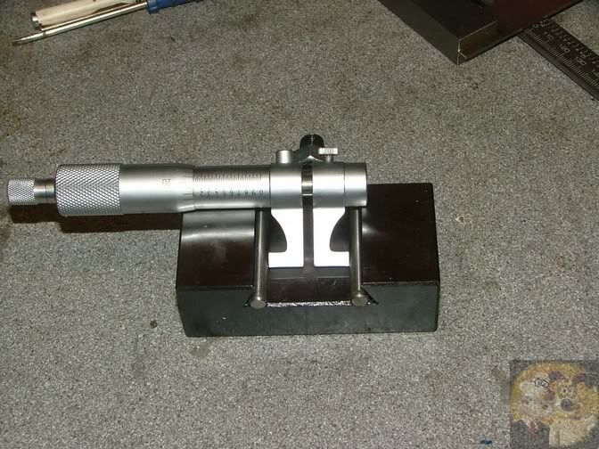
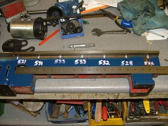
I began by removing the saddle.* I also removed the apron, though that is not necessary.*** On each side, there are 3 socket head cap screws and two adjusting screws.*** In this procedure, you remove the two end SHCS's and don't use them until the end.** You begin by alternately loosening the center cap screw, adjusting the two adjusters and tightening the center screw until you achieve a 30 mil gap at both ends of the cast iron strip.** In this case the gap is measured between the iron strips and the saddle.* I used a feeler gage to measure the gap.* This should be done for both sides of the saddle.*
The next step is to loosen the center SHCS and put the saddle back on the lathe.*** Tighten the center SHCS and measure the gap between the ends of the strap and the underside of the ways. ** This should be done at both ends and on both sides.** If the gap is zero, go back to the beginning and increase the initial gap to 40 mils.** But it should be greater than zero, so record all 4 values.** Remove the saddle again and do some math.** If the gap with the ways was 12 mils then you want to reduce the* saddle gap from the initial 30 mils to 19.* This will reduce the gap with the ways to 1 mil - the target.**
This should be done for both ends of the strip - so it is a balancing act between the two adjusting screws.** Once the correct gap is set at both ends of both sides, install all of the SHCS's but leave them loose.* Reinstall the saddle and tighten the center SHCS on both sides. ** If the 1 mil gap is correctly set, the carriage will move freely at this point.*** Then the end SHCS's are adjusted to achieve the desired trade between rigidity and friction.** At this point, you are bending the strips to close the one mil gap at each end.*
This method works very well and is much easier than it sounds.** It minimizes stress on the strips and achieves good balanced retaining force.* It may be old news, but I haven't seen it yet. * One minor point - to do this you need some narrow feeler gages.* I actually used shim stock to measure the strip to way gap.*


John, the plates under the saddle that control the adjustment appear to be straight, I tried them on a piece of glass, they do however show some signs of wear. Given we try to have some degree of precision, this seems a real imprecise way of setting up the machine, relying on 4 crappy little screws with locknuts, and 6 socket head screws to finish it off.

I have followed the above recommendation, then had to spend a while fine tuning, problem is start to tighten up the 4 outside socket head screws, it all goes tight, loosen off the adjusting screws, play is introduced:wall:

Ive got it close, not perfect, but I suppose with a cheap machine I cant expect perfection

Paul
 
Hey Norm, after reading way too much, I found this, it sort of made sense, it proved to be a reasonably reliable starting point, after another two hours of saddle on, saddle off and fine tuning, it feels a lot better than it was , virtually no play, until I slide the saddle to the ends of the bed, it gets tight, but I'm thinking those areas are out of the usual working area


Whilst this may be true, there is no indication of the true wear- possibly in the number 1 shear. My opinion and obviously from my guesses
 
My old lathe has wear of the ways near the chuck. My simple test is to set the locking gib for slight drag then roll the carriage towards the tail stock. Mine locks up about 1/2 way there so the ways are worn for sure. I could blue and scrape to make things better but I seldom use the full length of the machine so wear will happen again near the chuck.

I have accepted that this lathe will never be high precision but for my needs it works just fine.

Another point of view for your consideration.
 
After what feels like hours, I got the saddle to an acceptable fit, given its a used machine, and not exactly on the high end of quality! its real good, but, it does a job for me:thumbup:

So, during the build up process the biggest surprise was the cross slide, it had endplay, and after reading up, I had to sort out the fitting of the leadscrew, all was going well, slowly, slowly getting thing nice, then, would you know it I took too much of the locating plate thingy and it was too tight, so now had to clean up the screw, at the flange that goes into the plate (all the wrong terms, sorry!) but its now sorted.
Here come the idiot question, there is no play in the carriage, none in the cross slide or compound slide, I believe the apron lock nut is operating nice, so, I can move the saddle left and right by just pushing it, is this correct?

I was thinking, when turning, what stops it moving back away from the work piece? In the past, I never used the compound slide, I always used the apron wheel to advance towards the stock and held it, partly ignorance, and partly as the compound slide had play in it. I now know that was wrong, and I should be using the compound slide, do I lock the saddle with the locknut to stop the saddle moving?

Many thanks

Paul
 
Hi Paul,i have just bought a second 7x14 lathe and am proceeding with a no of mods.If you follow the thread you might find it interesting.Bazmak second lathe
 
I can move the saddle left and right by just pushing it, is this correct?l

Yes, that should be possible.

I was thinking, when turning, what stops it moving back away from the work piece? l

When you're turning an OD you will most often using the handwheel or leadscrew to move the carriage and the cross-slide to alter OD.
The top or compound slide spends most of it's life in the position which gives minimum overhang and maximum rigidity for normal turning and is predominantly utilised for tapers, precise short feeds and advancing thread cutting tools into the work at a set angle.
If you are using the top slide to machine a taper or a short, very precise part you would lock the carriage in place whilst doing this.

- Nick
 
many thanks Nick,

your explanation really hit the mark,

very much appreciated

Paul:thumbup:
 

Latest posts

Back
Top