Question for the Steamers

Home Model Engine Machinist Forum

Help Support Home Model Engine Machinist Forum:

This site may earn a commission from merchant affiliate links, including eBay, Amazon, and others.

cobra428

Well-Known Member
Joined
Apr 1, 2009
Messages
1,105
Reaction score
1
Hi Guys,
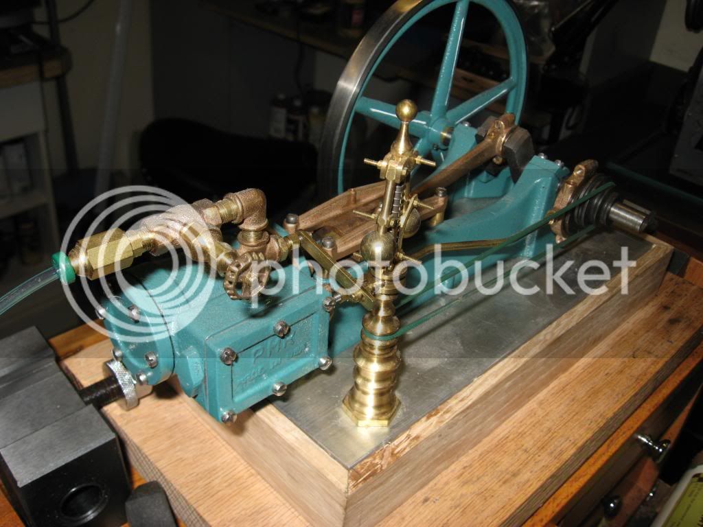
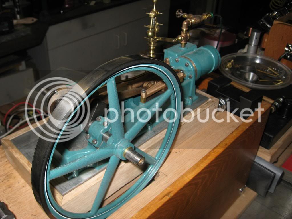
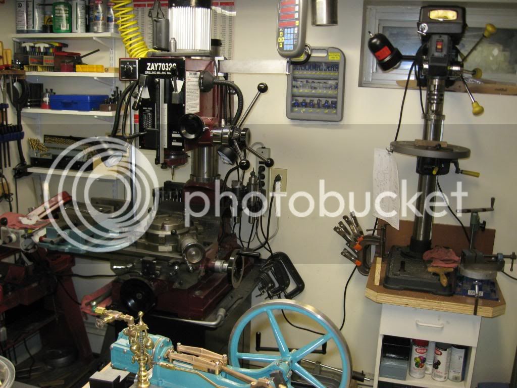
I have a question regarding where to go with my exhaust. I want to finish up a live steam display with a PMR boiler #1 and eng #1. It's only been 1 1/2 years since its been 90% complete with 90% to go :big: I want to clean up my shop from a couple of those projects abandoned for something better ???
PMR dumps the exh into the water refill tank in their instructions but....I've seen pic's of other methods (I think). One was a straight pipe to the top of the boiler stack and the other is the same but through a condenser first. I really would like to get the billowing white puff puff out the top of the boiler
Pro's... Con's?? A better way??

http://www.limws.org/Thumbnail-folders/Schaublin/Schaublin-Pages/Image11.html

Engine in bottom of pic PMR 1 with Electors gov. (mod)

IMG_0079.jpg


Any help gladly appreciated
Tony
 
:) :D ;D ;)

Hi Tony,

Nice shop, a place for everything and none of them in their correct place.... bit like mine.

To answer your question I have a question...... are you using a lubrication system on your engine? (very nice by the way).

If the answer is yes, then Under no circumstances can you run this back to your water feed tank and you really only have two choices remaining which are: -

1/ run the exhaust steam through a condenser to remove the steam oil and any condensate from the exhaust and then pipe the clean steam outlet from the condenser up the inside of the funnel to a point about 1/2" - 1" from the top.

or

2/ run it directly to the funnel top (as above) but leave out the condenser.
Unfortunately, if you choose this option you will have to be prepared for some spitting of water condensate and oil which will make a bit of a mess of your display and could spray unsuspecting onlookers with very hot and nasty gunge, I don't think they would be very appreciative of this. ??? :( :mad: :mad: (I would go with the first option).


If you are not using a lubrication system then either of the above would be Ok, again option 1 would be my choice, and the same problem with spitting water can occur, or you can run the exhaust back into your water feed tank, since it will not contain any oil.

Oil will create a lot of problems if you allow it to get inside your boiler. :( :( :(

Hope this is of some help in answering your question.

Best regards.

SandyC ;) :D ;D


Thanks SandyC,
I did make a lubricator for the engine and was planning to use it. So, condensor is in my build plans. Now all I have to do is figure out how to make one! I have the book Steam and Stirling Engines You Can Build. In the book is a V4 cyl osc with the whole plant, boiler condenser and .... I quess I'll follow that plan for a condenser.

For the full effect of everthing has it's place but .......

http://www.homemodelenginemachinist.com/index.php?topic=4817.0

Here's some pic's and and a video of my PMR #1
IMG_0160.jpg

Gov screws need cutting!
IMG_0161.jpg


Thanks Again
Tony

PS Stay well! We Need your know how :bow:
 
A very nice looking model. But I must make one criticism- the slotted head screws are a major turn-off to me. No real engine would have had such screws.

On my recent Rider Ericsson engine I used some hex stock and made all the bolts. You can get small hex head bolts, but watch out, many of the standard hardware store types have a very thin head that is very non-scale looking.

This is an item that really bothers me- Ive seen many otherwise very nice models that just look wrong with slotted head screws.
 
Ron
My first thought was that you were being "unfair", but after looking the engine over, I'm going to have to agree with your thoughts. I know you well enough to know they were not meant to offend anyone. That engine is just way too nice to not be outfitted with hex bolts. It would put the candles on the cake.

I'm the same way about socket head screws. They look fine if the engine is a Plain Jane type of project, but a well appointed engine like this one, at least in my mind, deserves to look as if it could be fitted to a real world job. Not meaning to offend anyone or appear critical, I've always felt that using the "right hardware" just makes a kind of statement.

Steve
 
Ronny baby,
I love you, we see eye to eye! Hardware completes the picture! Those are there for now. Trust me, after the full bling, those will be SS hex heads with washers. I am gathering a big collection of cheese head slotted 5-40 screws from the hardware kits that come with these kits good for assy and test not for bling. Give me a little time :big: I even have some 1/16 walnut to wrap around the cyl. And have some doll house bricks and grout to cover the base!
Tony

PS I was posting as you were Cedge Thank you for my defense
 
yes, I did not mean to offensive with my comment, sorry if anyone took it that way.

I also hold parts together with whatever is handy while building- more often now I use allen cap screws because they are so easy to hold. And while building a model we must remove-replace every screw about a thousand times.

When its all done is the time for the neat finish screws.

On my Rider I made them all form 12L14, but that can rust easily, so I plated them with an electroless nickel solution from Casswell.
 
Hey Ron,
No offense taken! I was thinking of getting a box of 5-40 allens too. Just because of what you said 1000 times. They are a lot easier to deal with than slots. How did you like the plating? I have the same kit from Caswell for a different project.
Tony
 
Ron, I have a PM Research kit (vertical coke bottle), too. It's always bugged me that you get cheesy hardware with the kit instead of hex heads. Mine weren't even brass, but some pre-rusted steel ones! I suppose that's the difference between a $100 kit and the more expensive Stuarts and others.
 
On the traction engines models it is usual practice to have the exhaust enter the base of the chimney and then turn it through 90 degrees so it blows straight up. The pipe is also reduced in size at this point to what is refered to as the blast nozzel, to increase the velocity.

This arrangement has a vast effect on the rate at which pressure can be raised and maintained as the steam flowing up the chimney draws the fire. Maybe not so critical if you are firing with gas but without it a coal fire will die.

This is the same principal as used on th efull size engines which are run with lubrication and no condenser.

Jason

PS Nuts & studs for me ;)
 
Hey Jasomb,
Thanks. I noticed on some models that the pipe into the stack was a smaller copper tube. Ah Ha that explains it, a nozzle/atomizer. Studs and nuts scratch.gif That's something to think about. I'm going to have to look in my Lindsay's steam books and see whats going on :idea:
Tony
 
Studs and nuts would have been the traditional way engines were mostly held together not bolts/screws be they hex head or slotted. If you do go for nuts then they were also taller than the mass produced nuts used in cars and construction and probably only chamfered on one face.

Jason
 
Say there Tony, what is the color name that you used on that #1 engine and whose label was on the container? It is an interesting shade, something different than the usual Greens, or Maroons etc.

BC1
 
Studs and nuts are probably more prototypical for a large stationary engine than hex head bolts.

The engine exhaust steam on locomotive and traction engines was directed up the stack to increase the fire draft. The steam pipe is fitted below the smokestack, centered on the stack, and about 1/3 the diameter of the smokebox down from the base of the stack. This exhaust is very effective in providing draft- you can actually see the fire brighten up on each stroke in a locomotive.

There was also a small steam pipe lead to this same point that was controlled by a valve so the fireman could increase the draft on a fire when stationary. This valve is called the blower valve. A few minutes before we pull out of the station we crack the blower to liven up the fire. Once underway we close the blower and rely on just the exhaust steam.

Stationary engines did not usually do this, they often had auxilary engines running blowers for fire draft, or they had very tall stacks for natural draft.

Marine engines never used a stack exhaust, they always ran condensing.
 
Thanks RonG
You just made up my mind for me! Studs and nuts it will be :bow:
Tony
 
Good call

You should have nuts & locknuts on the bearing caps, may have to turn the locknuts down from full nuts. Also aim for approx one turn of exposed thread on the studs above the nuts and a slight radius to the end of the studs. Ideally the studs should be threaded either end with a plain section in the middle not "allthread" or "studding"

And a nice gib key on the flywheel rather than that grub screw will finish it off.

Jason
 
BC1,
FYI The paint is a Krylon product, Engine Paint color Ford Green and I got it from McMaster
Tony
 
Is that really a shade of Green on your PMR engine? Gees' it looks to have a Bluish tint to it, at least to me anyway. I'm sure that you got the idea that was brought up RE: the use of studs etc, here are a couple of shots of that very thing on my #1. (which has yet to be finished :hDe: )

Cheers
BC1

DSCN1511.JPG


DSCN1512.JPG
 
Ron G.

RonGinger said:
.....Marine engines never used a stack exhaust, they always ran condensing.

Not necessarily true...It depends.

Many New York Harbor tugs ran non condensing simples. The NYC #16 for instance. In their casethey had water tanks on board...though I don't think they ran up the funnel.

Many Fresh water craft also ran non-condensing drawing water from the body they were in. I know several steam launches that do just that and exhaust their steam up the stack for draft...
 

Latest posts

Back
Top