


mklotz
Well-Known Member
A recent thread about proofing squares...
http://www.homemodelenginemachinist.com/index.php?topic=4094.0
got me to thinking. How could one quantify the accuracy of his square using only items available in the average shop? (Testing a square by drawing lines with two different orientations of the square will show whether it's more or less square but won't quantify how far out it is.)
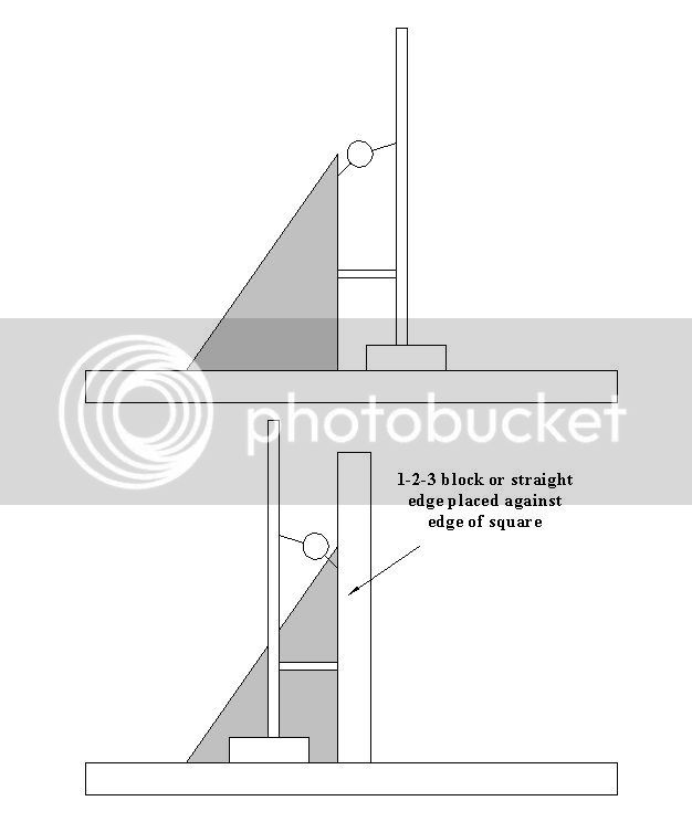
I came up with the scheme shown in the attached sketch. The square is placed blade up on a flat surface. A base is fitted with a mast that holds a spacer ring near the bottom of the mast and a DTI near the top. This base is placed such that the spacer ring touches the square's blade. In this position the DTI is adjusted to about half deflection and zeroed.
Now the base is slid over the beam of the square (a cutout in the base allows this to be done) and the spacer ring is pushed in contact with the opposite side of the beam. The reading on the DTI now indicates how far out of square the square is.
What do you think? Would it work?

http://www.homemodelenginemachinist.com/index.php?topic=4094.0
got me to thinking. How could one quantify the accuracy of his square using only items available in the average shop? (Testing a square by drawing lines with two different orientations of the square will show whether it's more or less square but won't quantify how far out it is.)
I came up with the scheme shown in the attached sketch. The square is placed blade up on a flat surface. A base is fitted with a mast that holds a spacer ring near the bottom of the mast and a DTI near the top. This base is placed such that the spacer ring touches the square's blade. In this position the DTI is adjusted to about half deflection and zeroed.
Now the base is slid over the beam of the square (a cutout in the base allows this to be done) and the spacer ring is pushed in contact with the opposite side of the beam. The reading on the DTI now indicates how far out of square the square is.
What do you think? Would it work?
")