Preamble to a Stirling

Home Model Engine Machinist Forum

Help Support Home Model Engine Machinist Forum:

This site may earn a commission from merchant affiliate links, including eBay, Amazon, and others.

remout

Member
Joined
May 4, 2010
Messages
17
Reaction score
0
Tormach CNC Mill
Experience level: none

I want to build a Stirling. I've got the plans from Jan Ridders and the more I looked at them the more I realized how much I don't know. I decided to start with Machinists wax and post the process here in hopes I will hear a better way of doing things.

Here is a pic of day one:

Flyweey.jpg


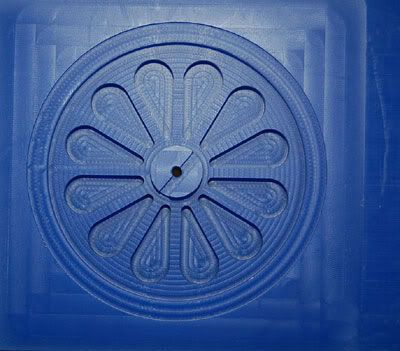
My steps today were:

Cut a 1" thick block of wax

One side was flat to I put it flat side down, in a vice, and faced a 0.0100" off of the uneven side to even it up. That was enough to take a bit off of the entire surface.

I then worked in a CAD program and cut what you see.

My plan for the next steps are:

Turn it over in the vice (using the center hole for alignment) and face down until it matches the first side. I cut the gaps between the spokes full depth so I would not have to worry about them not lining up.

I guess then I will have to carefully mount it independent of the vice so I can make the big circular cut and allow the stock material to fall away. This seems weird but I don't see another way?
 
In this photo the engine in the upper left the fly wheel was cut simular to what you are planning.
I wanted a curved spoke so I cut the center hub and the spoke cuts all the way through.

Then flipped mounted to a plate located on center or crank hole with 2 clamps inside and cut the od transferred clamps to out side and cut the under cut and hub.
I've made a few flywheels in this way but I now have no access to NC so I do everything conventional which takes more set ups and a different approach. But as I said your approach is sound you'll just need to work out the clamping on the second side.

group1.jpg
 
remout said:
I guess then I will have to carefully mount it independent of the vice so I can make the big circular cut and allow the stock material to fall away. This seems weird but I don't see another way?

That wax model looks nice! Bearing in mind that I've got zero CNC experience, couldn't you write your code to cut the outer perimeter as an "interrupted cut" , leaving a few places where you don't remove any metal to act as holding tabs so that the excess metal doesn't fly off, and then cut those by hand, leaving just a little bit of clean-up on the rim of the wheel?

I'm sure there are some CNC guys on here who will chime in the right terminology for what I've tried to describe! ;D

Cheers, Joe
 
My first attempt at a metal flywheel

flywheel.jpg


It turned out OK but I'll do better.
I mounted a lathe chuck on a piece of aluminum. I then clamped the setup to the mill table and used that to hold the stock.

I think my problem was due to centering. The first side turned out OK but the flip side is off center.

While the mill is great for cutting the inner design, it sure seems like this would be easier and better on a lathe.
 
remout said:
My first attempt at a metal flywheel

flywheel.jpg


It turned out OK but I'll do better.
I mounted a lathe chuck on a piece of aluminum. I then clamped the setup to the mill table and used that to hold the stock.

I think my problem was due to centering. The first side turned out OK but the flip side is off center.

While the mill is great for cutting the inner design, it sure seems like this would be easier and better on a lathe.
Looks pretty good for a first part I say.

For CNC flywheels, I've CNCed out the spokes and roughed the rim, then taken it over to the lathe to finish the rim.
 
How would I get a smooth finish on the face of the spokes? I can't get a fly cutter in there. Would this be done on a lathe?
 
remout said:
How would I get a smooth finish on the face of the spokes? I can't get a fly cutter in there. Would this be done on a lathe?
Check out Bogstandard's article on making flywheels from plate on a lathe-- http://www.homemodelenginemachinist.com/index.php?topic=1809.0 That's the lathe-way.
Otherwise you can always hand finish, tumble or sandblast them as well. I often tumble parts to get rid of the endmill marks. Unless your cutters are dull or the machine is out of tram, they're usually light and easy to remove.
 
What does "tumble" mean?

Oh Boy this feels like a stupid question:)
 
remout said:
What does "tumble" mean?

Oh Boy this feels like a stupid question:)
Basically putting the parts in with some polishing media (walnut shells, plastic media, rouge, etc) and shaking them around for a long time. Sometimes rotary drums, but most often vibratory bowl tumblers.

Caswells has a little bit on it: http://caswellplating.com/buffs/vibratory_tumblers.htm

A good source of small cheap vibratory tumblers are the ones rifle and pistol shooters use to clean brass cases for reloading. HF has a couple models. They'll take longer to do hard metals and the smallest don't like wet media.

 
Easy enough.

Any advice on what media works best with Aluminum and Brass?

Thanks!
 
I don't have a lathe so I'm stuck with the Mill

Success today!

flywheelv2a.jpg


flywheelv2b.jpg


It's round (a first)!
It has a decent finish, on the outer section, done with a fly cutter (a first)!
It has a chamfered radius (a first)!
All this learned right here...
No bandaids
No broken tools
No drama
Less than 1 hour to make (defiantly a new high water mark for me)


I just might be ready to move up to 4" and brass :)


Back
Top