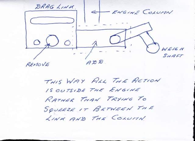
Hello Lads, as many of you know from reading my WIP thread I have/am still in the process of hacking together a different linkage to operate the twin valve sheaves on The Smitty. (ref. "building Smitty 101" in WIP section) I would like to see some detailed photos of how others have accomplished this, either from scratch or in 'kit/casting' form. Originally the drawings called for a rather long, silly looking "L" shaped lever attached to a spring that motivated the valve driving plate from side to side. I wish to fabricate a set of linkages that will do the same operated by a hand wheel arrangement similar to many of the marine types. I realize that the geometry of such set ups is critical but I still need to see some working examples to assist me in figuring out my problem. The linkage that I have made thus far has a tendency to want to move in a back and forth kind of rotation just a bit as opposed to merely swinging in an arc. I am thinking that the attachment point to the valve plate may or may not be suitable for what I am wanting to do. So, drawings, crap-O-Cad, or any sim programs would be most appreciated. I've been working on this for a little over a week and have hit a brick wall of sorts in finding a solution. Once I have a successful solution, I can complete this engine and move on to others in my stable. Thanks in advance :bow:
BC1
Jim
BC1
Jim


