Milling practice

Home Model Engine Machinist Forum

Help Support Home Model Engine Machinist Forum:

This site may earn a commission from merchant affiliate links, including eBay, Amazon, and others.

Mo deller

Well-Known Member
Joined
Mar 14, 2009
Messages
212
Reaction score
2
Thought I would share this interesting little job I have done for my cousins. They are keen on aviation history and have founded a museum based in Surrey UK. One project is a cockpit display from a P63 Kingcobra. They needed two seat brackets so they could bolt the seat on and came up with the original drawing for the part and asked if I could make them.
Not being required to fly they were not too bothered about fine tolerances which was just as well as they appear to me to be very close with the tongue being offset by 1 thou. Well that's if I read it right ;D.
Attatched the drawing and here's a photo of the brackets.
P39seatbrackets_1.jpg

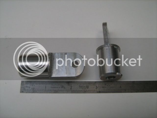
As I said it was good practice and I certainly need it on the mill. I find it very difficult to keep track of things and think about backlash and trying to re measure after you have made a few cuts. I found at one point I needed 16 thou off so I took 10 and measured again. Wow 1/2 thou undersize ??? Anyway I think they will probably do what is required of them.
Here's a link to their website
http://www.wingsmuseum.co.uk/

Peter.


P39 seat bracket drawing.jpg
 
Onya Pete, they look good to me
 
Thanks tel.

Did no aircraft buffs spot my deliberate mistake? Kingcobra is a P63 not 39 as I put ::). Doh I hate it when that happens.
 
I noticed it but I didn't think it worth jumping on. Looks good from where I'm sitting.
 
Those look good, Peter.
The odd one (or two) off part is one of the shop jobs that I get a lot of enjoyment from. These kind of things are fun. It's nice that you got to use a print!

I'd like to see that museum. Some day, if I ever get across the water...

Dean
 
Neat little job there. Looks good.

Some of these parts still catch me off guard, they appear easy until you get started.

Thanks for posting the print, I like looking at "real drawings". The prints you see nowadays lack the character of the hand drawn and lettered ones.

Not being required to fly they were not too bothered about fine tolerances which was just as well as they appear to me to be very close with the tongue being offset by 1 thou. Well that's if I read it right

Looks as though they wanted to avoid going beyond three place decimals. If I am reading it right, the decimal dimensions are +-.010 as noted in the title block, in which case .093 is close enough to half of .187.

Kevin
 
Thanks Jared, Deanofid and joeby.

Dean, hope you make it across one day. Nice web site you have.

joeby, glad you found the drawing of interest. I hadn't spotted the .010 reference you mentioned and it took me a while to find it. I don't understand why the measurement of 93 thou is there if the thing can be central anyway. Maybe it is just me not being trained to read drawings.

Peter.
 
Hello,

I am wondering how it was attached at the drilled end?

Best Wishes

Chuck M
 
speakerme said:
Hello,

I am wondering how it was attached at the drilled end?

Best Wishes

Chuck M

Hello Chuck, sorry I don't know at the moment. Both ends have drilled holes in so not sure which you mean. My cousin should get them this weekend so hopefully I'll get some feedback when he tries them for size :)

Regards
Peter
 
Mo, I believe the .093 dimension would fall under "design intent" or CYA. If it was not there, the machinist could place the .187 tab almost anywhere and still have a part in spec., going by the "do not scale drawings" rule. Then the liability falls back to the engineering department.

Sort of like the story about a machinist who had to make a tube of sorts, where the ID was dimensioned larger that the OD, so he turned a bag of chips in as the finished part.

I like the way the drawing has the "next assembly" table. You can easily look up the drawing for the mating part to see how it's supposed to fit. I haven't seen that on a drawing for a long time.

Also note everyone involved in the final part drawing has his name on the title block. That would give you the incentive to make sure you did your part correctly, I would think. The name of the individual who checked the drawing before release is also on there. I think standard practice these days is that the draftsman checks his own drawings, sometimes not a good thing.

The wife and I were doing some cleaning up around the house a while back, and up on a high shelf I found a stack of drawings I had done while I was an apprentice. The engineering department had AutoCad running on 286 and 386 computers, but you were not permitted to use AutoCad until you could correctly do, by hand, a complete set of prints for making a part. The drawings I have are the original hand drawings, done on vellum, with a lot of red marks on them. The Chief Engineer did all the checking on these and I had to redraw them with any corrections until they were right. I learned a lot about manufacturing from a bunch of people who were very good at what they did. Somehow, today, it seems as though most of that attention to detail is missing from the workplace.

Kevin
 
I understand what you mean regarding the 93 dimension. To someone like yourself who is trained to read it makes sense. I looked at it and it just seemed to draw attention to the fact it was off centre. If there had been no dimension but the centreline was drawn I would have took it to mean in the middle. I thought I studied it pretty well but next time I'll have a bit more understanding of what to look for.

There was one other thing that puzzled me though. The hole drilled into the round end appeared to have been changed in depth but was the same in the note at the top, 5/8 if I remember correctly,cant be bothered to look again now. I couldn't see a dia. mentioned for it. We came to the conclusion that it was not important in that it didn't locate on anything.
I'm interested to know how you would interpret that.

Peter.

 
Looks as thought the original drawing didn't call out the hole depth, only the 5/8" diameter. The depth was added in the revision.

It is more than likely a step to reduce the possibility of weakening the part by drilling too deep.

You are probably correct that it doesn't really matter for a non-flying aircraft. It would have mattered for the production part possibly for fastening. I imagine this part would be inserted into the tube and perhaps welded or drilled through the sidewall and held by screws or rivets. Possibly the hole was there for fastener clearance?

Speculation on my part.

Kevin
 
Nice job on the fittings Mo,

Chances are, the hole in the round is for weight reduction of the part. It doesn't seem like much, but when that is done on a hundred fittings it adds up over the whole plane.

Kenny
 
I still don't get that as I only see a reference to depth and none to dia. If you got that drawing would you take it to be a 5/8 dia to 5/8 deep?

Hello Kenny, I had wondered if it was purely to save weight. Hope to find out more when they get used.

Peter.
 
The leader note on the hole says 5/8 1 Deep. The revision block shows the change from no depth callout to the 1 Deep.

The drawing is a little fuzzy, but that's what it appears to be.

You will see various ways of calling out depths, most prints I've seen in the last few years that were generated by CAD programs indicate a depth by a line with an arrow pointing downward. That's all, no wording.

A little off the subject, but the callout, I would assume, means 1" deep at full diameter. A rule of thumb for a drill point is .3 times the diameter for the point on a 118 degree drill point. Using this to get a full diameter 1" deep with a 5/8" drill; .625 x .3 = .1875, 1 + .1875 = 1.1875 deep.

Kevin
 
Ahh yes I see. To my untrained eye all I could see was the depth. My mind was fixed then and I guess I just didn't register the line that was a number one as anything.
All a bit of a minefield it would seem.
Thanks for your explanation and I am glad it was of interest to you and the others. I wasn't sure if I should post it at first but glad I did now.

Peter.
 
I'm always happy to see that something I've posted may have helped someone.

The older, hand drawn prints are more interesting to look at for me, and I think I pay more attention to the little details on them than on the CAD generated drawings. I sometimes miss little things on CAD drawings and get called on it.

Glad you posted also!

Kevin
 
joeby said:
The older, hand drawn prints are more interesting to look at for me,
Kevin

Me too. They look like a real person did it. I much prefer working off hand drawn prints that stick to proper drafting conventions than the newer, more sterile stuff.

Dean
 
hi mo deller nice work on the fittings! got a couple questions if you dont mind.
first what order did you machine them?(turn od ,mill flat etc)i ask because i sometimes find myself unable to do
the next op. because i cant hold the part or cant dimension off it.

second did you use a rotary table to radius the end? thanks for any tips and again nice work!
shoprat
 
shoprat said:
hi mo deller nice work on the fittings! got a couple questions if you dont mind.
first what order did you machine them?(turn od ,mill flat etc)i ask because i sometimes find myself unable to do
the next op. because i cant hold the part or cant dimension off it.

second did you use a rotary table to radius the end? thanks for any tips and again nice work!
shoprat

Hello shoprat, yes I faced the end then turned the dia. and drilled the end. Then turned them round in the chuck and faced to length.
Onto the mill then held in a chuck on an upright rotary table. Milled the flats and then drilled the hole. The radius I marked out and hand filed.
I know what you mean about holding and measuring stuff. Can't think of any tips I'm afraid as this is a steep learning curve for me too. I find that measuring seems to become more difficult once I have started. Everything seems to get in the way ;D.

Best wishes
Mo.


Latest posts

Back
Top