


mklotz
Well-Known Member
I've long wanted to build a computer-controlled steam engine - to my mind the perfect marriage of antique and modern technology.
Now, I have some elementary theoretical and hands-on experience with electronics from my grad school days and years of building useful stuff - mostly with TTL chips (yes, I'm that old). However, I'm certainly no electrical engineer nor computer hardware expert and so I needed to educate myself about microcontrollers, which are the obvious choice for the project I'm contemplating.
So far, my efforts in that direction have been very rewarding and I wanted to pass along a bit of what I've learned to others who may be contemplating computer-controlled projects and are intimidated by the electronics involved in such an effort.
I bought the "BASIC Stamp Discovery Kit" from Parallax Corp. for $160.
http://www.parallax.com/Store/Micro...efault.aspx?SortField=ProductName,ProductName
Now before you stop reading because of the price, bear with me for a few paragraphs and you may come to understand why that's not as bad as it sounds.
This kit includes absolutely everything you'll need to hands-on learn about programming microcontrollers. It includes a manual (shown in the photo below) that will guide you through every step, even if you can't tell a resistor from a capacitor. (It's written at such a no-assumptions-about-the-reader level that it might even satisfy Zee.)
Before I get into the kit details, though, it's worth taking a few minutes to write about why you might want to know something about microcontrollers. Even simple timing and sequencing operations can require lots of components, serious electronic knowledge and some soldering skills to implement. Microcontrollers substitute simple programming skills for all that electronic know-how and solderless breadboards eliminate the need for soldering components plus, once a circuit has been built and evaluated, it can quickly be torn down and the components reused in the next exercise. The programming language is very similar to the old BASIC language - very conversational and easy to learn. The manual describes the language as simply and thoroughly as it describes the electronic details.
Ok, onward. Here's a photo of the board...
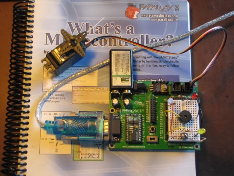
At the lower left is a connector that is used to connect the board to your computer. My old computer had serial ports so my board has a serial connector. Since my current computer is all USB, I use a USB-to-serial port emulator cable. If you have USB ports, you can buy the board already set up to accept a USB cable.
To the right of the connector is the Stamp microcontroller. It looks like a small circuit board of its own and it plugs directly into the main circuit board. On this mini-board are a number of components - a clock generator, the interface to the computer cable, an EEPROM to store the program, some power control circuitry and, at bottom center, the actual microcontroller (the black rectangle about the size of a pencil eraser).
Aside: The mini-board is about the size of a large postage stamp, hence the name "Stamp" microcontroller.
At top left the large black rectangle is a rechargeable 9V battery that supplies all power for the board. (An input jack for an external power supply is provided on the board but, for desktop programming, it's easier to use a battery.)
At far right, the white rectangle is a solderless breadboard where you plug-in components to perform the experiments in the manual. I'll write more later about the stuff you see plugged into it.
The red-white-black cable leads to an ordinary radio control servo as used in RC models.
The board has plugs for attaching four servos directly and more can be added using the breadboard.
Some connectors, a power switch and a power-on LED round out the complement of stuff on the board.
How do you use it? The kit supplies you with a programming editor that you install on your computer. Using that editor, you write a program to perform the task(s) you wish to accomplish. Press the editor "RUN" button and the program is automatically downloaded into the EEPROM and stored there. Press the "RESET" button on the board and the program runs. My programs always run perfectly the first time out") but, if you need to make corrections, simply make them in the editor and repeat the process.
but, if you need to make corrections, simply make them in the editor and repeat the process.
I wrote a simple demo program to show a few things. The code looks like this...
Don't attempt to understand the entire program but do glance at the code so that you can see how natural the programming language is. It only has about fifty commands so learning it is a weekend's work.
The program is exercised in the video below. Once the program is started, it flashes the red LED in the upper right of the breadboard exactly seven times.
Aside: Building a circuit to flash an LED is no big accomplishment but building one to flash exactly a prime number of times would require some rather clever circuitry.
After flashing the LED, the controller waits for me to push the sequencing switch in the bottom center of the breadboard. It indicates that it's waiting by lighting the yellow LED at lower right.
When the switch is pushed, it flashes the two color (red/green) LED at upper left exactly ten times. (It's a bit hard to see the two colors in the video but they're there.) Then it waits on the sequencing switch again.
Next it exercises the servo, moving it to its extremes and center point and then executing a slow sweep (as would be used in an optical search implementation).
Finally, it plays a few sounds through the piezoelectric speaker - the round black cylinder in the middle of the breadboard.
[ame]http://www.youtube.com/watch?v=NI7-0pGZmTw[/ame]
Now think about it. That's a lot of controlling and manipulating for a breadboard that contains little more than five resistors, a few wires, and the controlled circuit elements. Try duplicating that level of control without a microcontroller and you'll get a feel for just how useful this device can be in your shop.
A few more words in this (already lengthy) monologue...
The Stamp has sixteen I/O ports, each separately programmable, so the capacity for controlling a serious number of operations simultaneously exists.
You will have noted that, during the video demo, the board was not connected to the computer. The board can be run in stand-alone mode - think of controller embedded in a project. Also, the Stamp can be removed from the board (carrying its program with it) and used in other breadboards or projects.
You can buy more Stamps from Parallax and use the board to program them. This makes the $160 price tag a bit more palatable.
When connected to the computer, the microcontroller can "talk back" to your computer, displaying messages, counts, and information it's acquired on a "debug screen" that is part of the editor. This raises the possibility of using it as a data acquisition or monitoring device.
I'm certainly not an electronic expert but I'll try to answer any questions you might have. There are certainly others on this board who know far more than I on this subject. Please feel free to correct any mistakes I've made or add to the information presented here.
Finally, I hope at least a few of you find this information useful.
Now, I have some elementary theoretical and hands-on experience with electronics from my grad school days and years of building useful stuff - mostly with TTL chips (yes, I'm that old). However, I'm certainly no electrical engineer nor computer hardware expert and so I needed to educate myself about microcontrollers, which are the obvious choice for the project I'm contemplating.
So far, my efforts in that direction have been very rewarding and I wanted to pass along a bit of what I've learned to others who may be contemplating computer-controlled projects and are intimidated by the electronics involved in such an effort.
I bought the "BASIC Stamp Discovery Kit" from Parallax Corp. for $160.
http://www.parallax.com/Store/Micro...efault.aspx?SortField=ProductName,ProductName
Now before you stop reading because of the price, bear with me for a few paragraphs and you may come to understand why that's not as bad as it sounds.
This kit includes absolutely everything you'll need to hands-on learn about programming microcontrollers. It includes a manual (shown in the photo below) that will guide you through every step, even if you can't tell a resistor from a capacitor. (It's written at such a no-assumptions-about-the-reader level that it might even satisfy Zee.)
Before I get into the kit details, though, it's worth taking a few minutes to write about why you might want to know something about microcontrollers. Even simple timing and sequencing operations can require lots of components, serious electronic knowledge and some soldering skills to implement. Microcontrollers substitute simple programming skills for all that electronic know-how and solderless breadboards eliminate the need for soldering components plus, once a circuit has been built and evaluated, it can quickly be torn down and the components reused in the next exercise. The programming language is very similar to the old BASIC language - very conversational and easy to learn. The manual describes the language as simply and thoroughly as it describes the electronic details.
Ok, onward. Here's a photo of the board...
At the lower left is a connector that is used to connect the board to your computer. My old computer had serial ports so my board has a serial connector. Since my current computer is all USB, I use a USB-to-serial port emulator cable. If you have USB ports, you can buy the board already set up to accept a USB cable.
To the right of the connector is the Stamp microcontroller. It looks like a small circuit board of its own and it plugs directly into the main circuit board. On this mini-board are a number of components - a clock generator, the interface to the computer cable, an EEPROM to store the program, some power control circuitry and, at bottom center, the actual microcontroller (the black rectangle about the size of a pencil eraser).
Aside: The mini-board is about the size of a large postage stamp, hence the name "Stamp" microcontroller.
At top left the large black rectangle is a rechargeable 9V battery that supplies all power for the board. (An input jack for an external power supply is provided on the board but, for desktop programming, it's easier to use a battery.)
At far right, the white rectangle is a solderless breadboard where you plug-in components to perform the experiments in the manual. I'll write more later about the stuff you see plugged into it.
The red-white-black cable leads to an ordinary radio control servo as used in RC models.
The board has plugs for attaching four servos directly and more can be added using the breadboard.
Some connectors, a power switch and a power-on LED round out the complement of stuff on the board.
How do you use it? The kit supplies you with a programming editor that you install on your computer. Using that editor, you write a program to perform the task(s) you wish to accomplish. Press the editor "RUN" button and the program is automatically downloaded into the EEPROM and stored there. Press the "RESET" button on the board and the program runs. My programs always run perfectly the first time out
but, if you need to make corrections, simply make them in the editor and repeat the process.I wrote a simple demo program to show a few things. The code looks like this...
Code:
' {$STAMP BS2}
' {$PBASIC 2.5}

'MICROCONTROLLER DEMO PROGRAM

p CON 15
s CON 12
d CON 250
i VAR Word
duration VAR Word
frequency VAR Word

DEBUG CLS
LOW 1

'Blink red LED seven times

FOR i=1 TO 7

DEBUG ? i

HIGH p
PAUSE d
LOW p
PAUSE d

NEXT

GOSUB switch_wait  'wait for the carbon-based computer

'operate bi-color LED ten times

FOR i=1 TO 10

HIGH 14  'red
LOW 13
PAUSE d

LOW 14  'green
HIGH 13
PAUSE d

LOW 14
LOW 13

NEXT

GOSUB switch_wait  'wait for the carbon-based computer

'operate the servo

DEBUG CLS,"CCW 10 o'clock",CR

FOR i=1 TO 150
PULSOUT s,1000
PAUSE 10
NEXT

DEBUG "CW 2 o'clock",CR

FOR i= 1 TO 150
PULSOUT s,500
PAUSE 10
NEXT

GOSUB Center

DEBUG "Continuous CCW motion",CR

FOR i=500 TO 1000
PULSOUT s,i
PAUSE 10
NEXT

GOSUB Center

GOSUB switch_wait  'wait for the carbon-based computer

'make some sounds with the piezoelectric speaker

FOR duration=15 TO 1 STEP 1
 FOR frequency=2000 TO 2500 STEP 20
 FREQOUT 9, duration, frequency
 NEXT
NEXT


DEBUG "all done"     'indicate program completed

END

'--------------------------------------------------------

switch_wait:      'wait for switch to be pushed

HIGH 1         'light yellow LED to indicate waiting

agin:
IF (IN0 = 1) THEN
 LOW 1
 RETURN
ELSE
 PAUSE 100
 GOTO agin
ENDIF

'-------------------------------------------------------

Center:       'drive the servo to its centered position

DEBUG "Center 12 o'clock",CR

FOR i=1 TO 150
PULSOUT s,750
PAUSE 10
NEXT

RETURN
Don't attempt to understand the entire program but do glance at the code so that you can see how natural the programming language is. It only has about fifty commands so learning it is a weekend's work.
The program is exercised in the video below. Once the program is started, it flashes the red LED in the upper right of the breadboard exactly seven times.
Aside: Building a circuit to flash an LED is no big accomplishment but building one to flash exactly a prime number of times would require some rather clever circuitry.
After flashing the LED, the controller waits for me to push the sequencing switch in the bottom center of the breadboard. It indicates that it's waiting by lighting the yellow LED at lower right.
When the switch is pushed, it flashes the two color (red/green) LED at upper left exactly ten times. (It's a bit hard to see the two colors in the video but they're there.) Then it waits on the sequencing switch again.
Next it exercises the servo, moving it to its extremes and center point and then executing a slow sweep (as would be used in an optical search implementation).
Finally, it plays a few sounds through the piezoelectric speaker - the round black cylinder in the middle of the breadboard.
[ame]http://www.youtube.com/watch?v=NI7-0pGZmTw[/ame]
Now think about it. That's a lot of controlling and manipulating for a breadboard that contains little more than five resistors, a few wires, and the controlled circuit elements. Try duplicating that level of control without a microcontroller and you'll get a feel for just how useful this device can be in your shop.
A few more words in this (already lengthy) monologue...
The Stamp has sixteen I/O ports, each separately programmable, so the capacity for controlling a serious number of operations simultaneously exists.
You will have noted that, during the video demo, the board was not connected to the computer. The board can be run in stand-alone mode - think of controller embedded in a project. Also, the Stamp can be removed from the board (carrying its program with it) and used in other breadboards or projects.
You can buy more Stamps from Parallax and use the board to program them. This makes the $160 price tag a bit more palatable.
When connected to the computer, the microcontroller can "talk back" to your computer, displaying messages, counts, and information it's acquired on a "debug screen" that is part of the editor. This raises the possibility of using it as a data acquisition or monitoring device.
I'm certainly not an electronic expert but I'll try to answer any questions you might have. There are certainly others on this board who know far more than I on this subject. Please feel free to correct any mistakes I've made or add to the information presented here.
Finally, I hope at least a few of you find this information useful.
