Bernd
Well-Known Member
I was asked if I would do a small write up on how to make a counter bore tool, form here on in call a c'bore. So here's the write up.
First for you newbies who may not know what a c'bore is. This is a commercial one. It followed me home from work many long years ago.

It is made up of three pieces, the pilot (left), the cutter itself (middle), and the holder (right) This one has a pilot size of .385", the cutter 5/8" dia. and the holder is universal. It will hold a range of different size cutters and pilots. You can use different size pilots with the same cutter. It all depends on the size hole you have and what size you want the c'bore to be. The pilot has a very fine thread on the small dia. to hold the whole works together.

Now we are going to make our own c'bore. It's very simple. First you will need a piece of drill rod (silver steel) close to the dia. of the c'bore you need. For example, for a 2-56 screw you will need a c'bore of .375" dia. for the head of the screw and .201" dia. (#7 drill) for the pilot. Chuck a piece up in the lathe and follow the diagram below.

Next set up your vertical mill with a vise and some parallel packing such as shown in the diagram below. Use a cutter close to dia. of the drill rod (silver steel) and proceed slowly cutting the teeth of the c'bore. Make sure the center of the cutter goes past the pilot shoulder. You can either cut 3 flutes or 2 flutes or more if you so desire, but 2 or 3 will do the job nicely.

Once you are done cutting out the flutes you will need to back off the top land of the cutting edges. Use some kind of marking compond so you can see when you have approximately .010" to .015" of top land left on the cutting edge. Same for the sides of the flutes. They will need clearance on them too. I've marked it as 10 degrees but less will do also, say down to about 7 degrees.

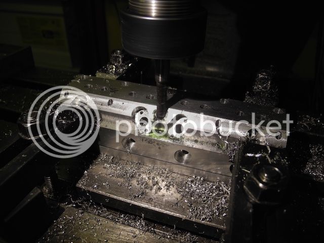
Here's a picture of what it looks like in the mill. You'll notice that I used a hex cutter fixture I made. You don't need it to make that one tool, but it is nice to have if you are going to make several of different sizes. It's nothing more than a piece of cold rolled hex stock with a .500" reamed hole. I then made a bushing to hold smaller dia. stock.

Here I'm filing the clearance angles on the back side of the cutting teeth. Notice that I'm using a safe file. (one with no teeth on the side) This will keep from marking up the side of the pilot.

Here I'm filing the Clarence angle on the back side of the flutes.

Your cutter is now ready for use in aluminum or brass. If you are going to use it in any kind of steel I would recommend that it be hardened. That's another whole subject in itself.
I made several cutters before I got one to cut properly. It seemed like I never quite got my filing of the angles down properly. Also you can use this method to make all sorts of other cutters, such as, two lipped end mill, counter sink, that special tap you can't seem to buy. I got these methods from "The Shop Wisdom" series put out by Village press and the Bedside reader series by Guy Lautard. Very valuable books to have in my opinion.
If you have any questions on making a c'bore please feel free to contact me through this site or my e-mail address. I would be more than happy to answer any questions you might have. If I can't answer them I'm sure some one here will.
Regards,
Bernd
First for you newbies who may not know what a c'bore is. This is a commercial one. It followed me home from work many long years ago.
It is made up of three pieces, the pilot (left), the cutter itself (middle), and the holder (right) This one has a pilot size of .385", the cutter 5/8" dia. and the holder is universal. It will hold a range of different size cutters and pilots. You can use different size pilots with the same cutter. It all depends on the size hole you have and what size you want the c'bore to be. The pilot has a very fine thread on the small dia. to hold the whole works together.
Now we are going to make our own c'bore. It's very simple. First you will need a piece of drill rod (silver steel) close to the dia. of the c'bore you need. For example, for a 2-56 screw you will need a c'bore of .375" dia. for the head of the screw and .201" dia. (#7 drill) for the pilot. Chuck a piece up in the lathe and follow the diagram below.
Next set up your vertical mill with a vise and some parallel packing such as shown in the diagram below. Use a cutter close to dia. of the drill rod (silver steel) and proceed slowly cutting the teeth of the c'bore. Make sure the center of the cutter goes past the pilot shoulder. You can either cut 3 flutes or 2 flutes or more if you so desire, but 2 or 3 will do the job nicely.
Once you are done cutting out the flutes you will need to back off the top land of the cutting edges. Use some kind of marking compond so you can see when you have approximately .010" to .015" of top land left on the cutting edge. Same for the sides of the flutes. They will need clearance on them too. I've marked it as 10 degrees but less will do also, say down to about 7 degrees.
Here's a picture of what it looks like in the mill. You'll notice that I used a hex cutter fixture I made. You don't need it to make that one tool, but it is nice to have if you are going to make several of different sizes. It's nothing more than a piece of cold rolled hex stock with a .500" reamed hole. I then made a bushing to hold smaller dia. stock.
Here I'm filing the clearance angles on the back side of the cutting teeth. Notice that I'm using a safe file. (one with no teeth on the side) This will keep from marking up the side of the pilot.
Here I'm filing the Clarence angle on the back side of the flutes.
Your cutter is now ready for use in aluminum or brass. If you are going to use it in any kind of steel I would recommend that it be hardened. That's another whole subject in itself.
I made several cutters before I got one to cut properly. It seemed like I never quite got my filing of the angles down properly. Also you can use this method to make all sorts of other cutters, such as, two lipped end mill, counter sink, that special tap you can't seem to buy. I got these methods from "The Shop Wisdom" series put out by Village press and the Bedside reader series by Guy Lautard. Very valuable books to have in my opinion.
If you have any questions on making a c'bore please feel free to contact me through this site or my e-mail address. I would be more than happy to answer any questions you might have. If I can't answer them I'm sure some one here will.
Regards,
Bernd