Making a prismatic tool height setting guage for the lathe

Home Model Engine Machinist Forum

Help Support Home Model Engine Machinist Forum:

This site may earn a commission from merchant affiliate links, including eBay, Amazon, and others.
Joined
Dec 26, 2008
Messages
3,697
Reaction score
685
Location
Crewe, Cheshire, UK
This is a carry over from a little while ago where I was discussing one of these tools.

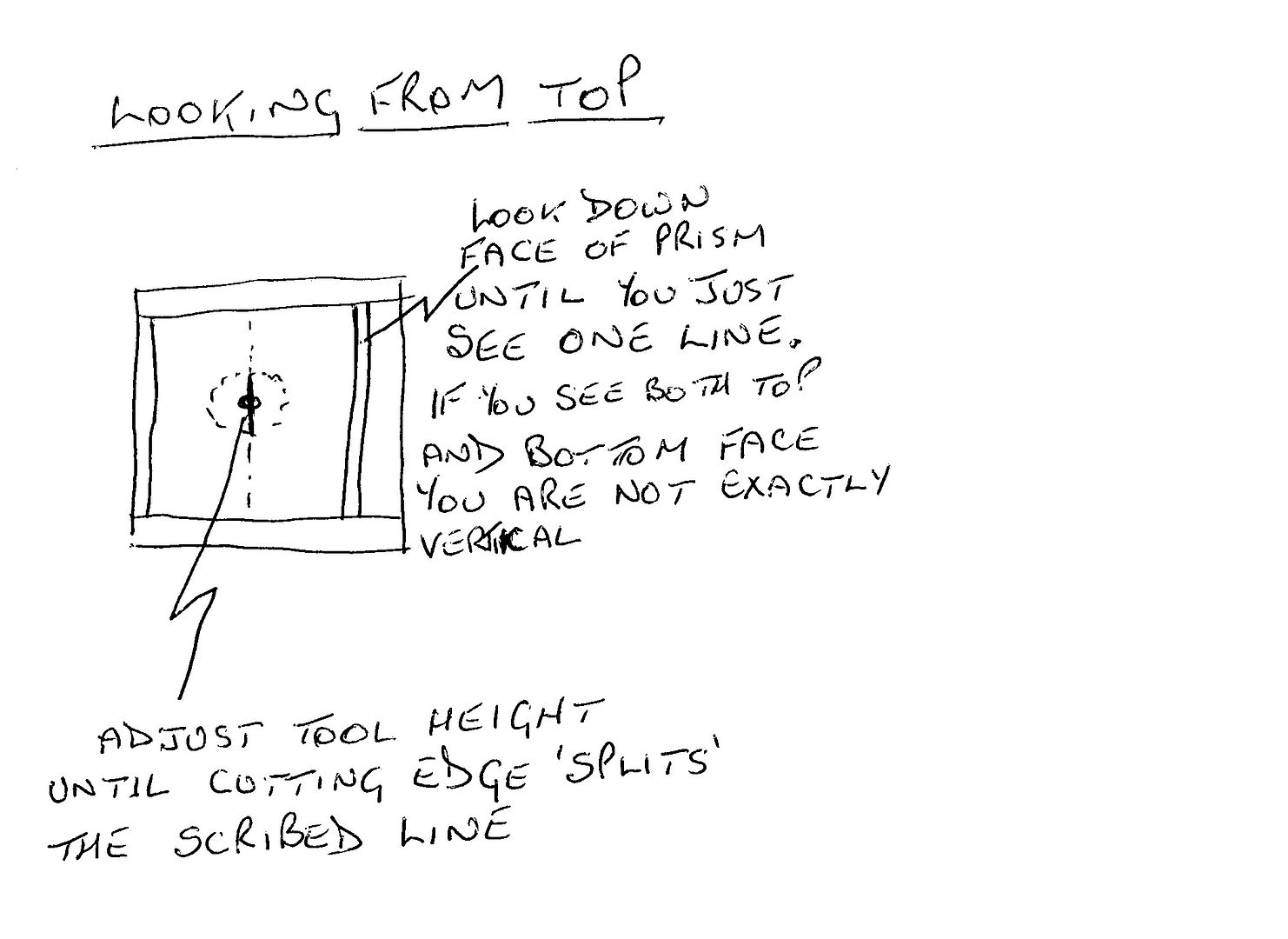
This little device is needed by myself because I can't now get down low enough to use my 'split the line' gauge that I have used for a fair while now. I was going to use a 10mm prism but thought better of it and I am now using a 15mm one. I bought a pair of them from China at just under 10 pounds for the two.

These are now my ramblings where I used what I had to hand and designed it on the go.
---------------------------------------------------------------------------------------------

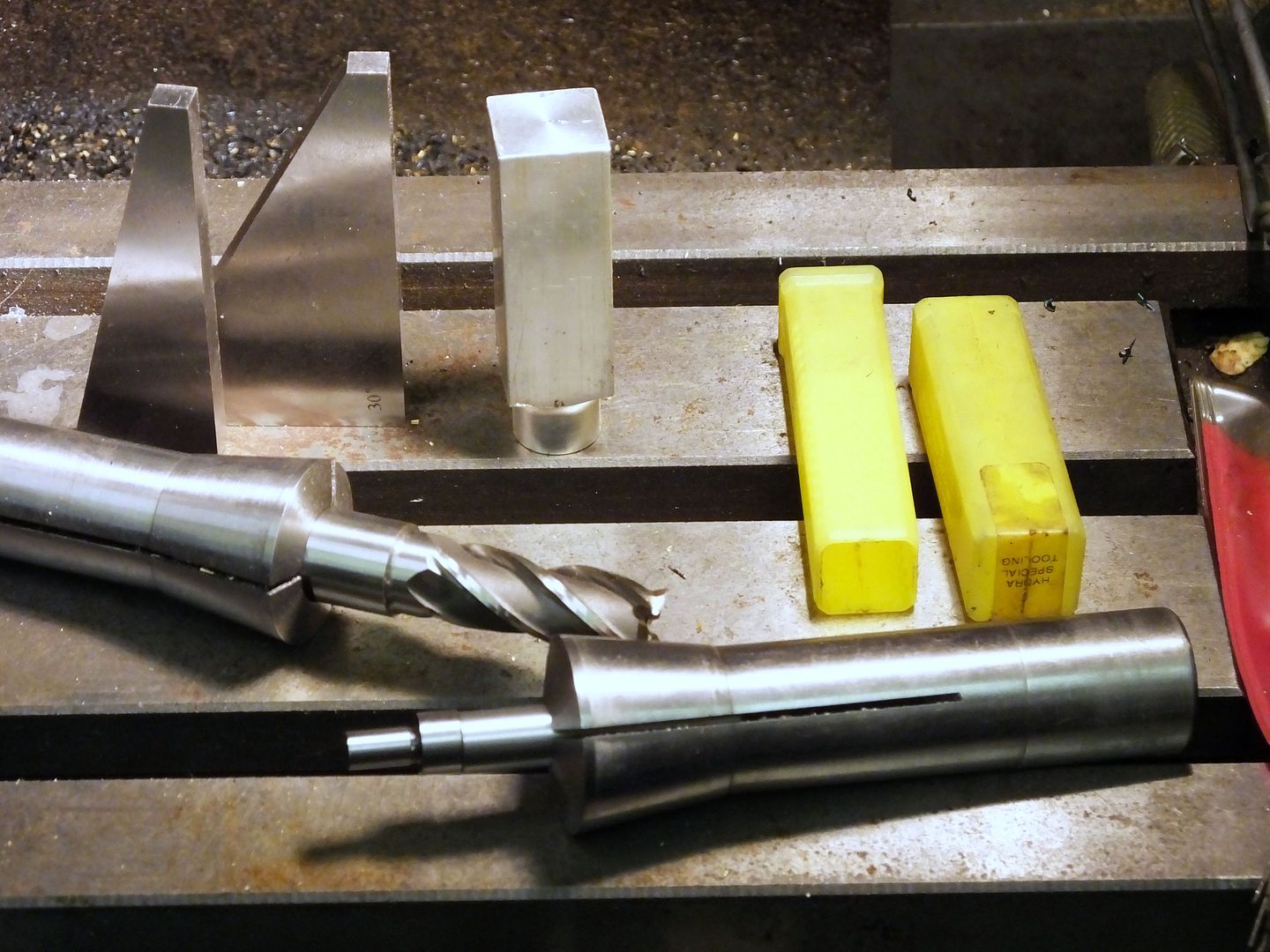
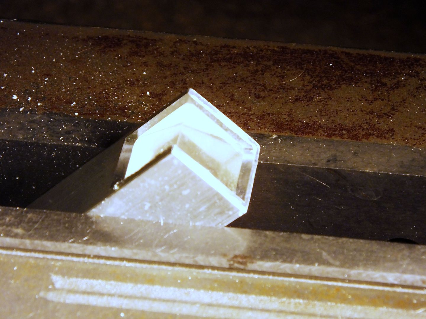
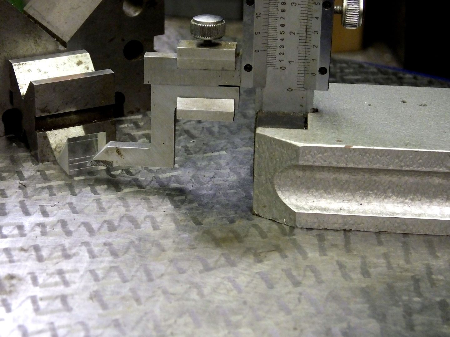
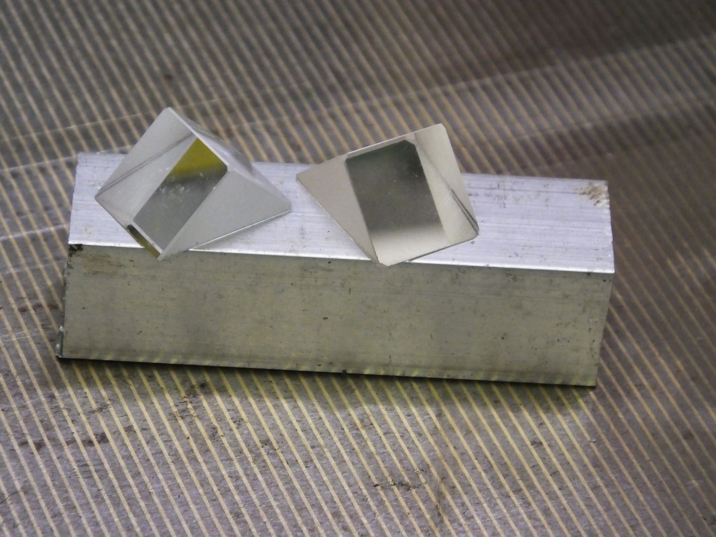
These are a few of the bits, a 2.75" length (not critical) of 3/4 ali bar, and the couple of prisms I mentioned above.

Prism%2001_zpsuad9z4ho.jpg


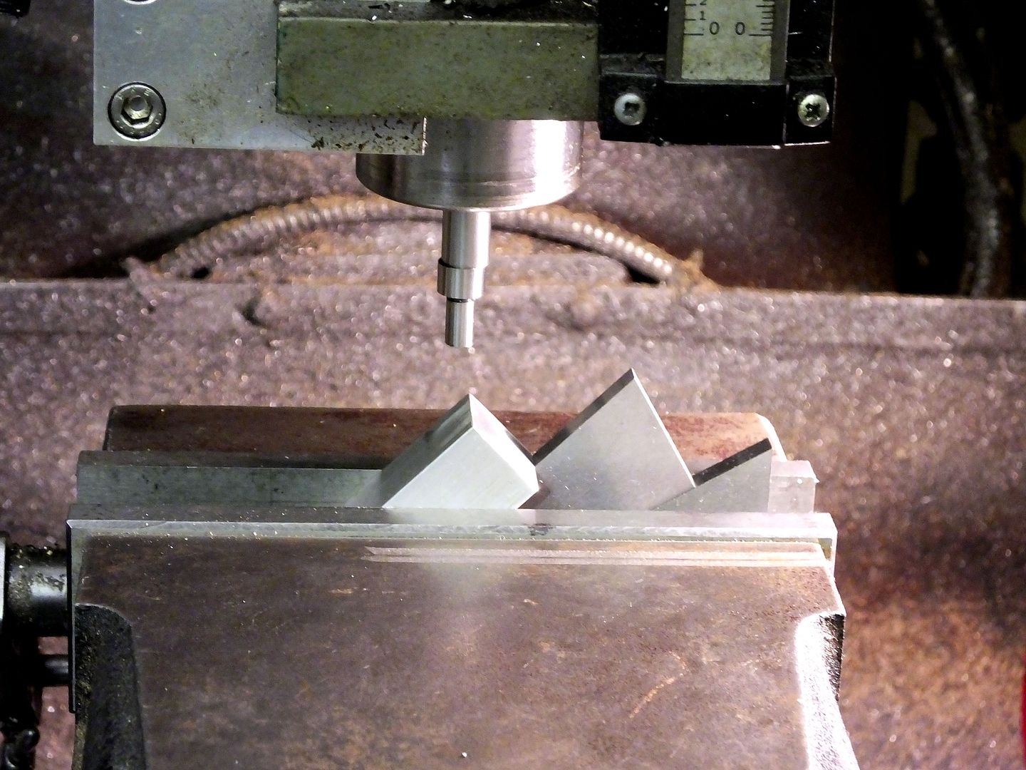
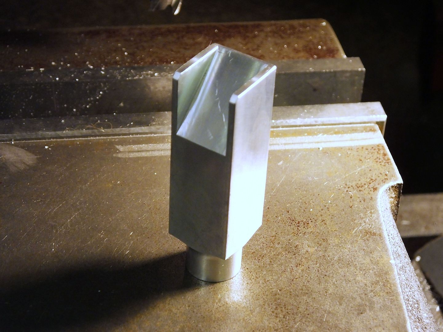
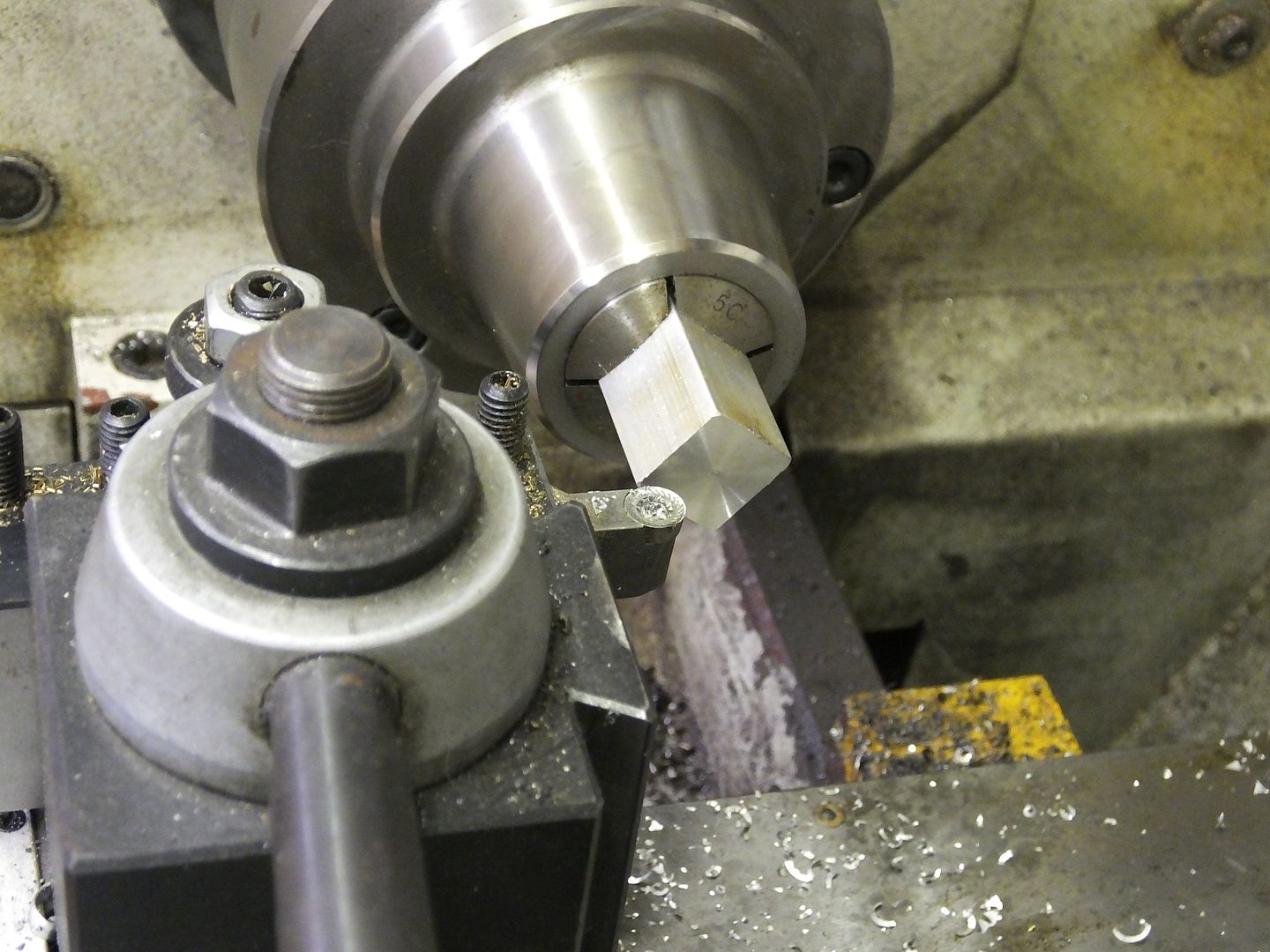
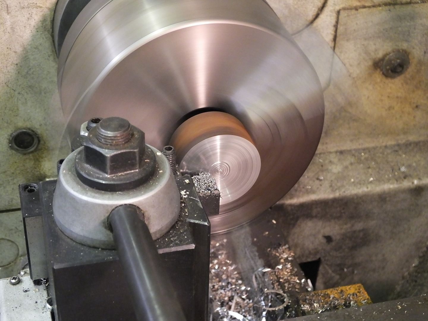
Both ends of the bar were faced up with one of my favourite cutters, a profiling tool.

Prism%2002_zpsnqa44e63.jpg


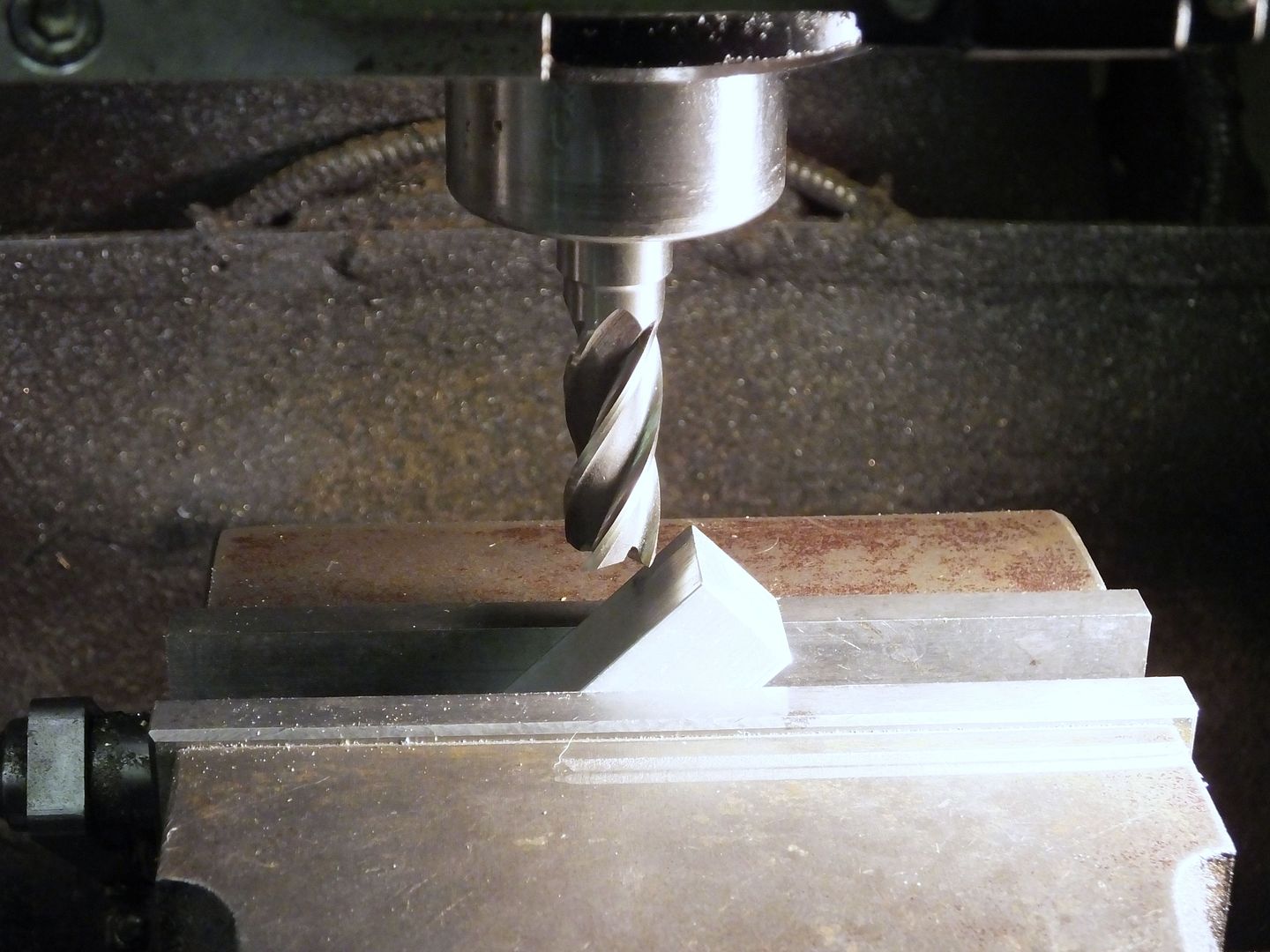
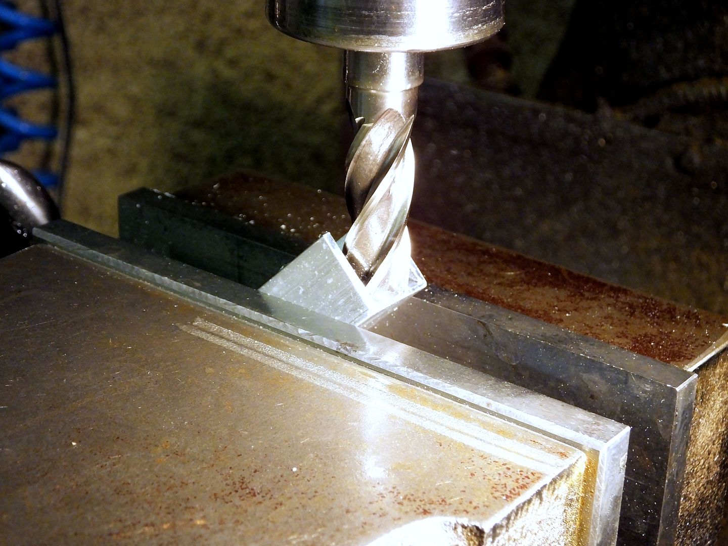
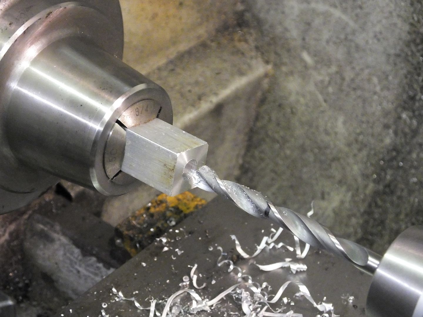
A 9mm bullet point drill was was used to drill about 1" deep in one end. This drill should have been 8.9mm, but what is 0.1mm between friends.

Prism%2003_zpsflohyfzo.jpg


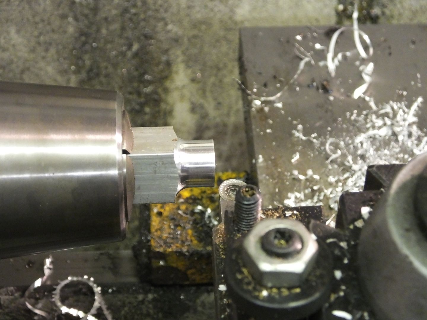
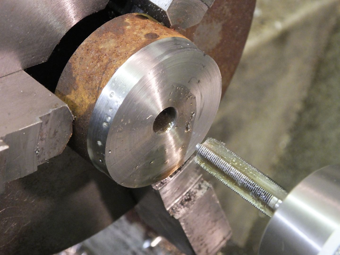
The end of the bar was profiled down a little, just so that certain items don't become bulky, namely the locking nut.

Prism%2004_zpszabrmnx3.jpg


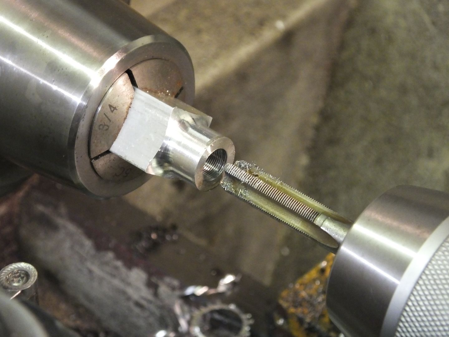
The 1" deep hole was then tapped out to 3/8" x 40 TPI model engineering thread.
The reason I used this thread, which I use on almost all things like this, it gives a nice fine adjustment as one full revolution gives 0.025" rise or fall, the same as an imperial micrometer.

Prism%2005_zpsuofyh9ca.jpg


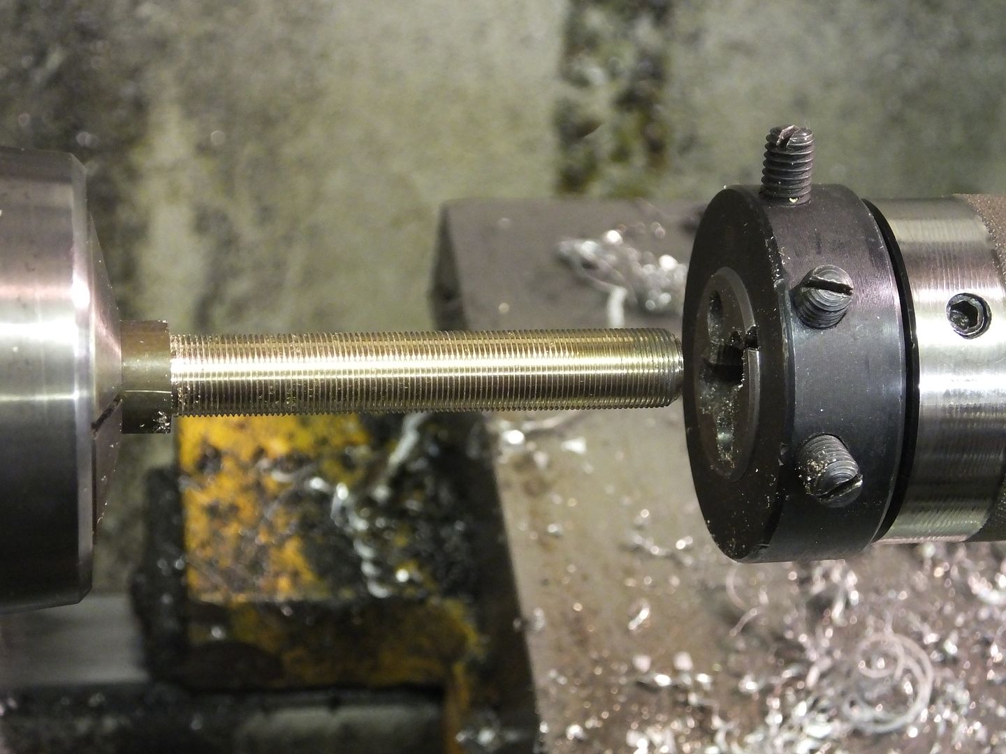
Next up was a piece of brass bar turned down to 3/8" by about 2.5" long and given the same sized thread as above. The length of these parts would need to be made so that the finished tool can be adjusted to length for your particular lathe centre height.

Prism%2006_zpszdh3qjep.jpg


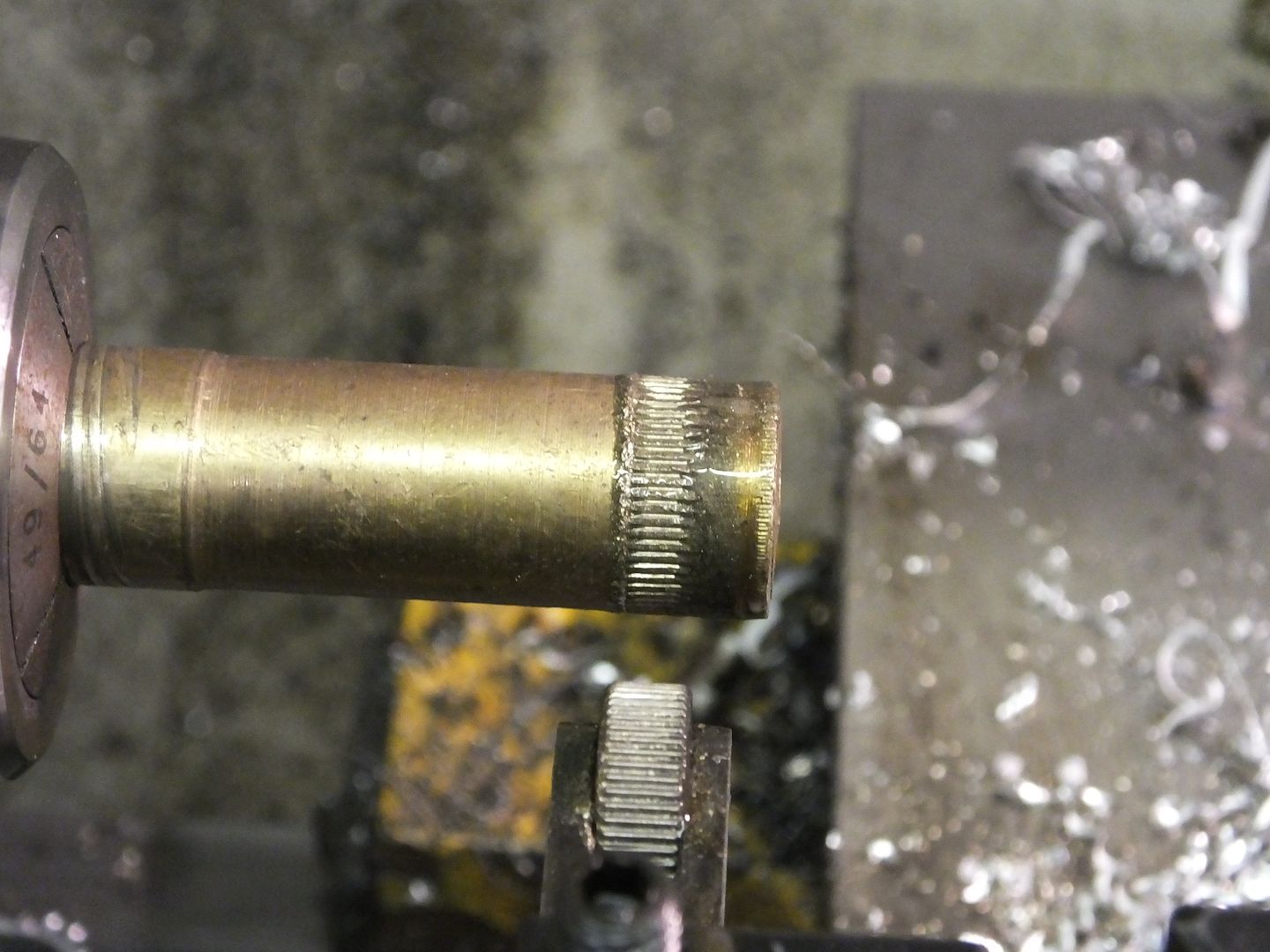
Another bit of brass was drilled and tapped through and a bit of straight knurl given to the outside.

Prism%2007_zpsrlsjft70.jpg


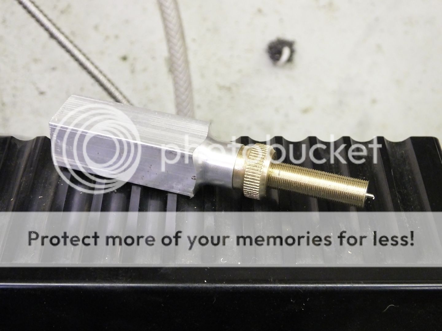
The brass locking knob was given a bit of a profile by eye and the three parts assembled to check for fit.

Prism%2008_zps8yp2197s.jpg


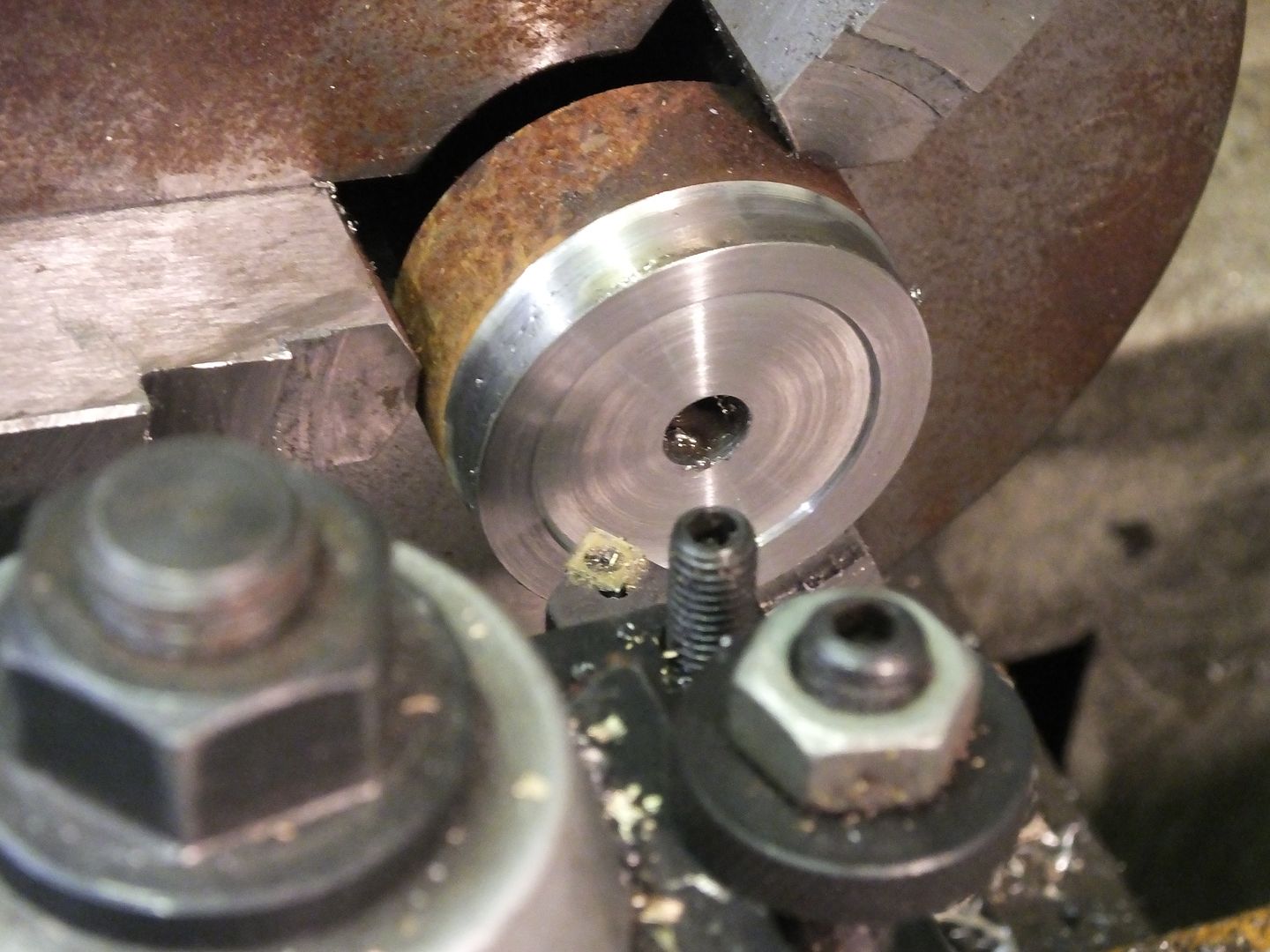
I stepped outside my workshop door and found a bit of rough stuff which was about the right size, so I mounted it up into a soft jaw chuck (it just so happens where I had bored it was near enough the right size) so this can help me keep things straight and parallel. One end was faced, and a bit down one side as well.

Prism%2009_zpspvwvhbnl.jpg


This time, the piece part was drilled all the way through and the usual thread cut through it.

Prism%2010_zpsiickdvxt.jpg


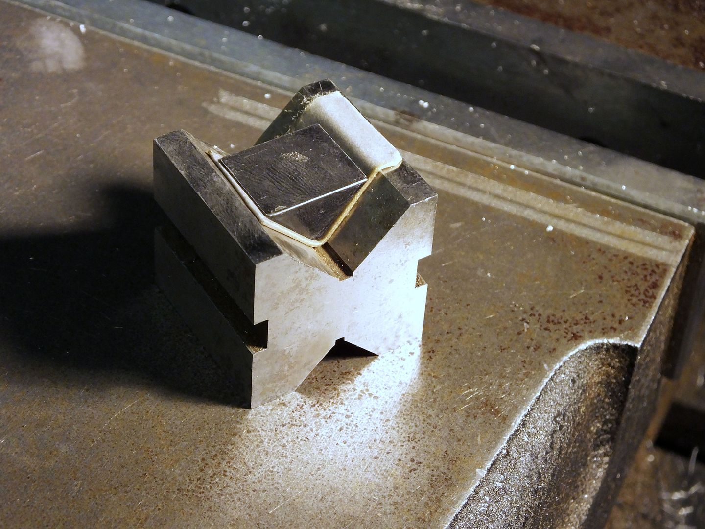
A small recess was formed into the bottom of the base just so that there is less chance of a bit of swarf kicking the tool off upright.

Prism%2011_zps6cvs7lny.jpg


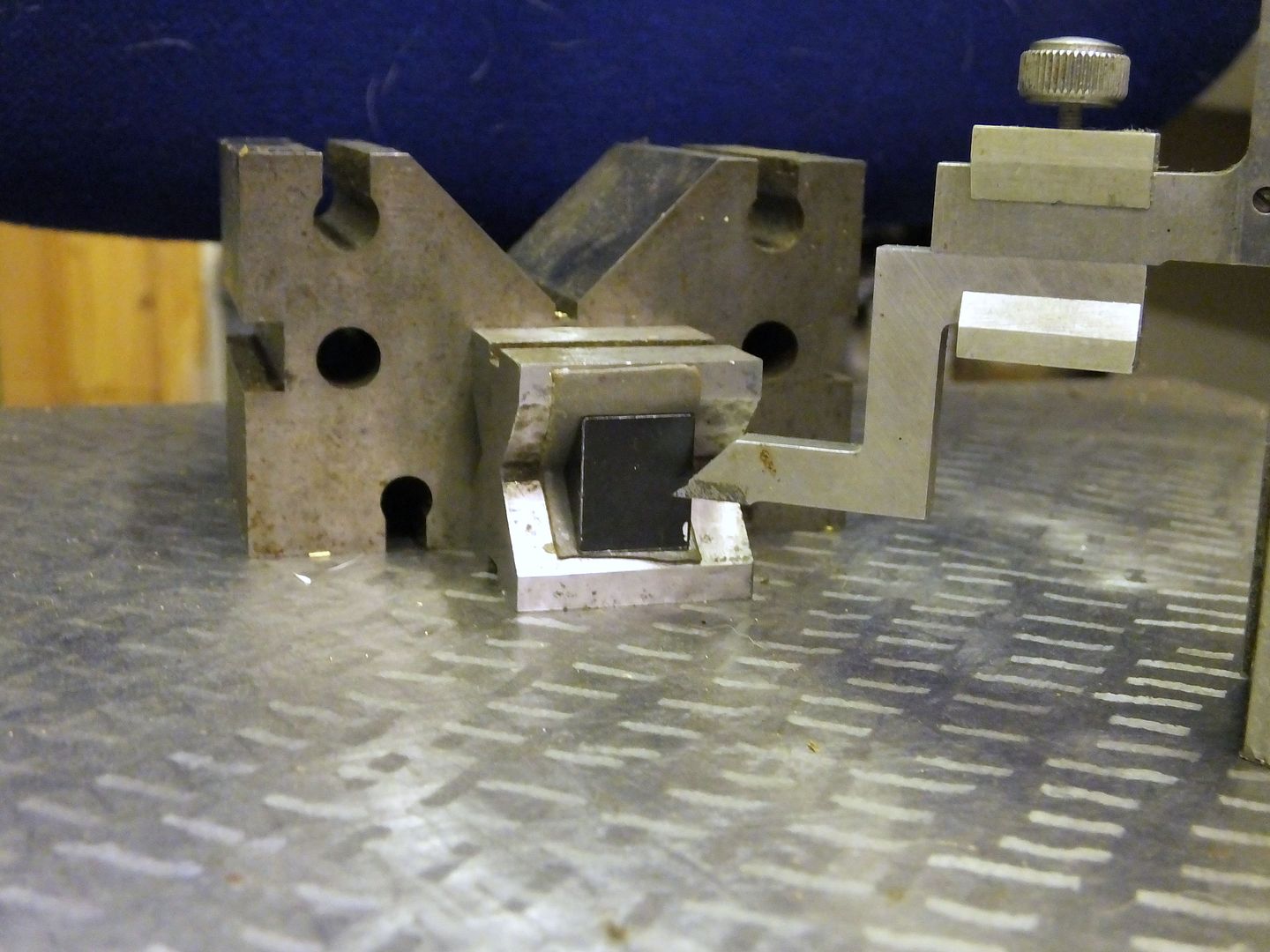
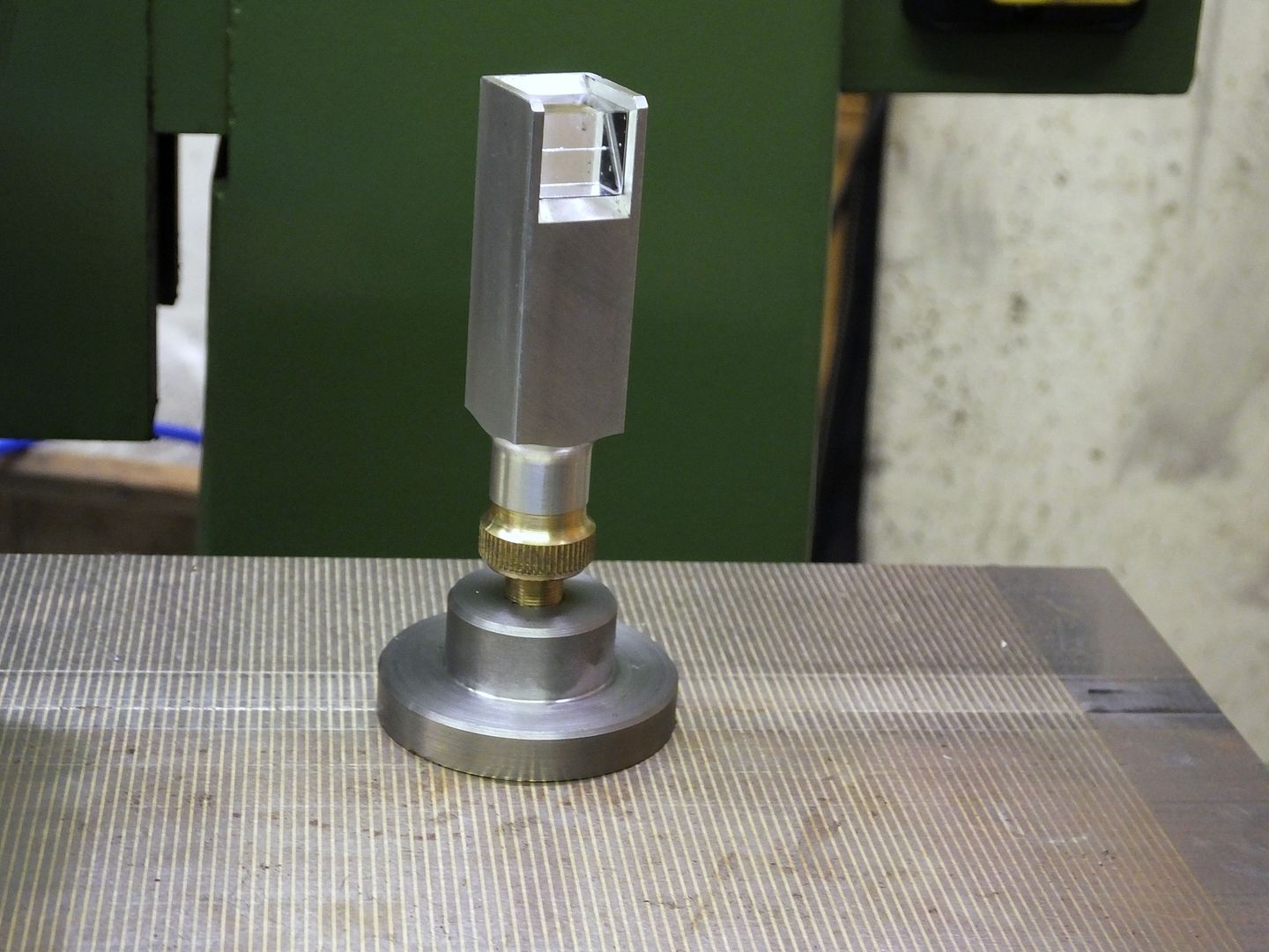
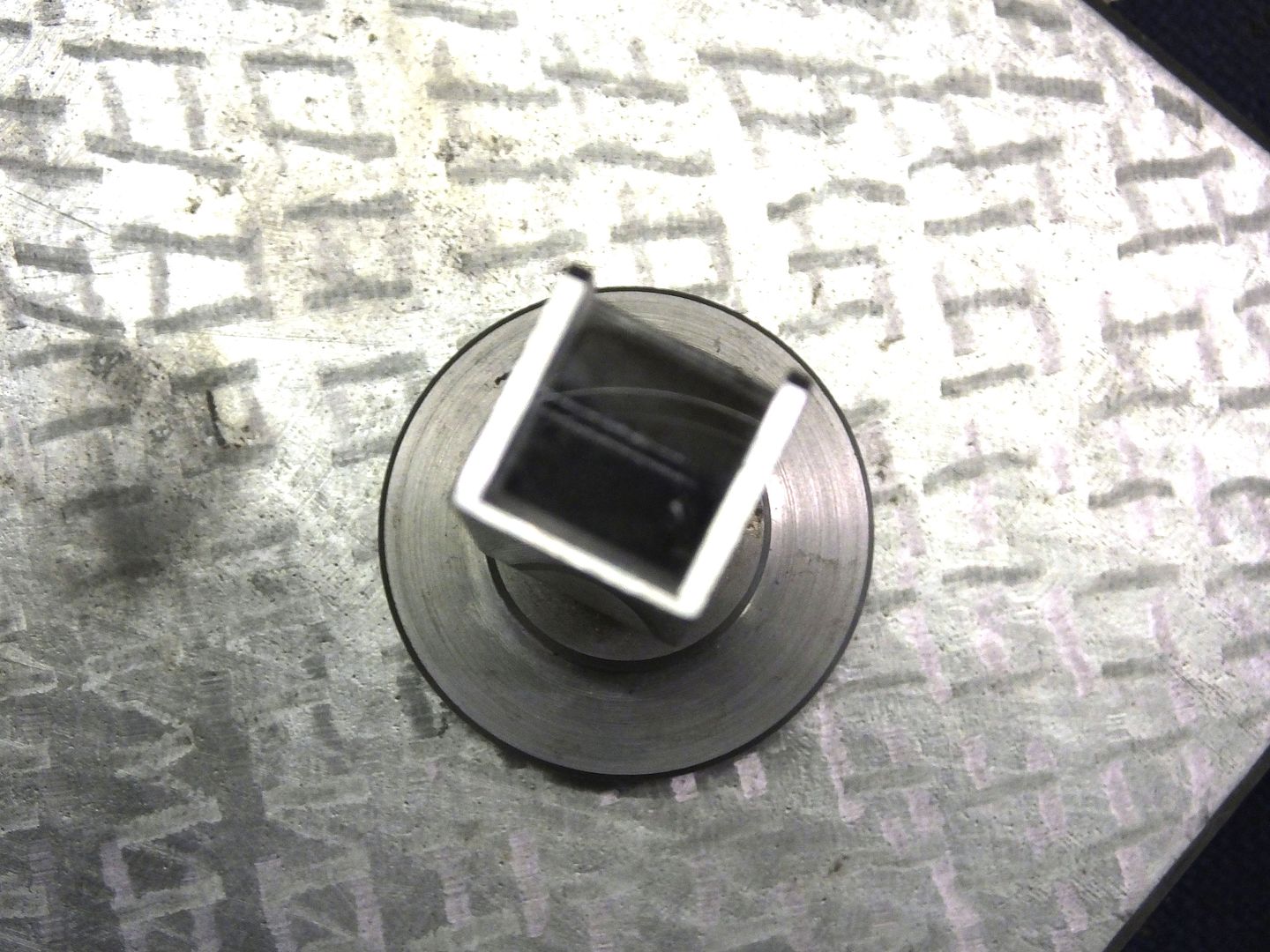
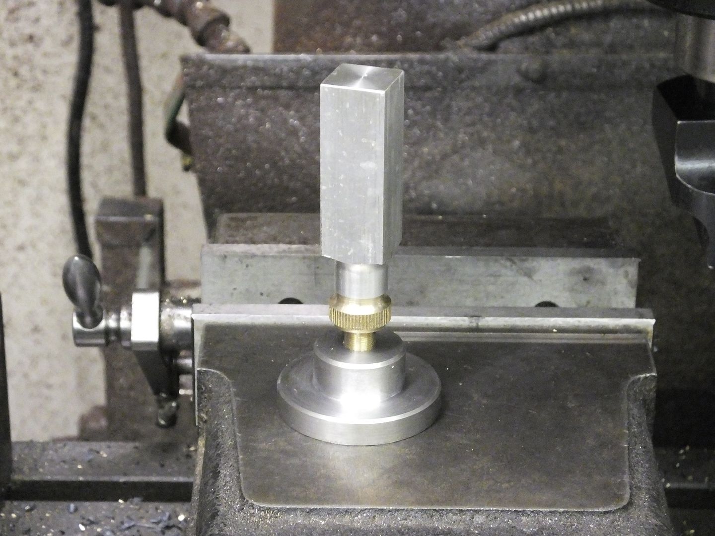
The part was turned around in the soft jaws and a bit of profiling was done to reduce weight and make it look a little nicer. All the bits were then assembled to make sure I can get the adjustment I need.

Prism%2012_zps5mgllr6k.jpg


So this is as far as I go now, I will finish the write up tomorrow if all goes well.


John
 
I'll have to read that again but I like it!

My recent 'exploit' so far is to use a USB Microscope for £50 from Maplins. There was one at £30 too.

So my recent exploits were to photo my broken tooth implant and send it to my daughter who has a Master's in Dentistry for comment.

Again, my 6 way turret is finally to arrive, hopefully to fit on my MyfordS7B and probably I'll need something for alignment.

So I'm also wondering about your idea for either my Stent or Clarkson T&C.

So keep posting

Thanks

Norman
 
Thank you Norman, but as I said before, I have a couple of 7mm cameras that would have done the job but it is all the trailing wires and need of a computer to display it that put me off.

BTW, I used what materials I had available for this job, it could have been a bit of round for the top and square for the base, as long as the prism can be mounted (next installment) then everything should be fine. Same as the thread used, it was only because it is what I have, almost anything can be used within reason.

John
 
John, Thanks!

Really, I am too old to understand any of these electrical gadgets. As you see, I haven't a clue on how to post pictures here.

Probably not interested but who knows?
Best Wishes

N
 
Now to the second part of this build, milling machine work.
-----------------------------------------------------------------------------

So to start, this is a picture of the bits I will be using.
A couple of angle blocks that when put together give me 45 degrees, a 14mm tungsten end mill cutter and my Starrett imperial edge finder, because the material is imperial and I need to find the centre.

Prism%2013_zpsbjkhniwz.jpg


So the part was set into the vice resting on the two angle blocks and the centre of the job was found, I then reverted to metric to cut the slot in the top to take the 15mm wide prism.


Prism%2014_zpsytemommf.jpg


Now that I was on centre, the table Y axis was locked up, the angle blocks removed and the cutter put into the spindle ready to start cutting in the X axis.

Prism%2015_zpsofdclscf.jpg


I was soon down to depth, then I stepped either side of centre with the cutter by 0.5mm and took a cut along each side face, this is to give me the 15mm width I require.

Prism%2016_zpsaqpgub4t.jpg


Notice how deep I went with the slot, this was done to give a bit of protection to the prism during use. The prism fitted perfectly.

Prism%2017_zpsaxtacagx.jpg


The completed metal bit for the top half of the tool.

Prism%2018_zpscykox16t.jpg


Now came the delicate bit, scribing a line across the long edge of the prism, you only get one go at this so I decided to try it out on one of the 'bit knocked about' prisms that I had off my mate.
So using a piece of heavyweight double side tape, the prism was bedded down into the V of a V block.

Prism%2019_zps26vgbwi5.jpg


I sharpened the tungsten edge of my height gauge on a very fine diamond lap until it was sharp enough to shave with, then set it to half the height of the V block.
Holding the block very tight, I scribed my line across it.

Prism%2020_zpsbshkxi7f.jpg


With a minuscule amount of superglue down the corners of the mounting slot, the prism was stuck in there.
I am leaving this 'old' prism in there as it looks to be very good as it is, the line from this angle looks a little thick, but actually it isn't, it is the same thickness as my split the line gauge, which will be great for me.

Prism%2021_zpsqzvkxxpp.jpg


I did try it out on my lathe cross slide, just to see how easy it was to use, so I fitted a centre into the tailstock and checked it out from about 1" away from the centre. I set the line until the centre split the line, then moved the tool away to about 4" away, it was still perfectly splitting the line, so a bit of a result.
With my troublesome eyesight, I thought I would have to fit some sort of magnification onto it, but I could see it perfectly clearly, plus it was very easy for me to look over the top of my toolpost to see everything, I think I may have cracked it, but until I feel good enough to get back on my lathe, things will have to wait a little longer before I do things in earnest and actually set a tool up with it and try it out.

Prism%2022_zpsrpxh3cj3.jpg


John
 
That's an interesting Doo-dad John, nice job!
I'll have to dig through my bit box, there's some prisms in there somewhere!

- Nick
 
Thank you Nick.

I have yet to try it out in anger, but from preliminary results it looks like it will solve my problems.

The one I saw at a model engineering show at Olympia, London (hundreds of years ago) was a very basic affair, with a prism just stuck onto the top of a bit of round bar which was held in a base similar to mine with a grub screw to give up/down adjustment. So it could be made almost any way as long as it works, mine is just like I do anything, belt and braces and made to the best of my abilities.

John

BTW, this is really the first machining project I have completed and shown since I became active again, and hope to pick up a few more of my previous trailers as I become more confident about it. Those failed because I was overstretching myself at the time.
I have relearned a lot about my machines doing this one, but I did have trouble with getting my mill running again, I had forgotten what all the buttons do and the DRO was just out of my league for about an hour, I just kept pressing buttons to see what they did, and had to reset a few times because I confused it somewhat.
 
Nick,
Don't go too fast as I have hit a problem with my method after trying it out actually setting it up. I found that eyeing down the front of the prism as shown in my sketch just wasn't wasn't accurate enough, so I am going to scribe a couple of lines on the two other faces rather than the hypotenuse. Like the chap in the link I gave, he used two lines for alignment on his.

It isn't safe enough yet for me to get back in the shop, and a brain scan this Thursday should see what is going wrong.
When that is sorted (hopefully), I will get back in there and show the results with the new prism.

John
 
Sorry this fix has taken so long, being banned from entering my shop by my doctor doesn't help.

So taking life into my own hands and not having any machines running I managed to get this little tool working perfectly.


I measured down the short sides and halved it using my height gauge.
Then using the gauge I scribed short lines on each of the short faces, after sharpening up the tip again, glass soon makes it blunt.

DSCF6311_zpsjl3mlg0x.jpg


So a quick stick like I did before with the prism and it was ready for use. Sorry about the fuzzy pic, but it does show what I was after.

DSCF6315_zpss9ib5w3x.jpg


Now this time it really does work perfectly.

Line up the two scribed lines by eye, then raise or lower the tool tip until it is perfectly in line with your two overlaid prism lines. It is as easy as I say it.

I tried it out on a couple of known height tools, and it showed them perfectly in line.
I am not allowed to run machinery at this time, but will prove it if ever I am allowed back in the shop by the medicos.

Job done, but not quite dusted.


John
 
Steal away Pete, all my ramblings are free to anyone who wants to read about them.

I have been having to do things like this for the last 10 years or so, just so that I can keep on machining. Unfortunately, falling over with the collywobbles three or four times a day looks like it might be the end of it all, unless they can do something about it.

John
 
Last edited:
Check me on this, John.

The two lines need to be exactly the same distance from the 'back' corner of the prisim.... right? The closer to exact they are, the more 'accurate' the level when the two lines are viewed through the face of the prisim?

Thanks,
Pete
 
John

This really looked like a neat project and I have been following along. I have drawn it up in CAD but not built it yet. I included a picture and have some questions. I did not get the position of the scribed faces although I think I figured it out.

The model on the right shows the long face attached to the mounting block with the two scribed lines one on the top and another on the side - is that correct? And as Pete asked is the distance from the edge I show to each line the same? It would appear that must be critical.

Is there a third scribed line on the long side? See picture of prisms.

When I get some prisms I will give this a try. I found some that 18mm wide with a 22mm long face, says they are for fingerprint systems and cost about $7.

Thanks for the help.

Bob

Prism Ht Gage Drawing.jpg
 
Bob,

Only two scribed lines are required, the one on the long (hypotenuse) is not required, that was my first attempt which didn't work.

As long as the two scribed lines are done from the right angled corner, and at the same height from that corner, then they will be at the correct relationship to each other, it is just that I wanted mine to be exactly half way up the face, they don't have to be.
Also, I didn't scribe all the way across the faces as the height gauge had trouble starting from the very edge, as long as there is enough to line up with each other, then it is fine.
Be careful with the type of prisms you obtain, they MUST be mirrored on the hypotenuse (long) face otherwise the tiny amount of glue used to stick it down will show through when you try to align the lines. You could get away with non mirrored ones if you use a mechanical method of fixing it in place, say a tiny brass or nylon grub screw either side, plus you need to have an almost mirror finish on the angled face it will sit against, or maybe a tiny bit of flattened out cooking foil underneath the prism.

Hope this helps.

John
 
Last edited:
Well, I've ordered a few prisms, 10mm and 15mm sizes, and when they get here I'll make up one of these gadgets for my lathe. I've already thought of ways to use such a thing as a 'level' for set-up and lay out work on various projects....

Brilliant, John, just brilliant!!

Pete
 
I'm glad it will be of use to you Pete.

All from something I saw at a model show many years ago.

It just needs someone like yourself to find other uses for the concept.

I have thought about using one for setting the tool length if ever I get my CNC mill up and running as the height setters are rather expensive to buy.

John
 
Pete

where did you find your prisms? I know the ones I am looking at do not
have a mirrored surface as John suggests. The mirrored ones I find are over $100 each!

Thanks

Bob
 

Latest posts

Back
Top