I don't know either. I'll ask the next time I see him. It seems another issue is how well the engine breathes, but the auxiliary exhaust should help that issue. I had been thinking 5:1. 6:1 sounds good.
But first, a mock up and a lot more thinking is in order.
What do you mean by auxiliary exhaust? The exhaust gasses will be forced out the exhaust valve on the exhaust stroke. A restrictive valve will only require more power to do so.
By auxiliary exhaust, I mean ports located at the bottom of the cylinder, as in a 2 stroke engine. That leaves less exhaust to exit the undersized valve.
Now that is really old-school!
I have never herded or seen such an engine running. I only know that they did it that way in the early days (and quit it). But I really like that idea!
That's pretty funny nick. What's the fun in taking maybes and wild guesses out of the equasion? Isn't that the spice of life? The CH47 Was nothing but maybes and wild guesses and according to modern aerodynamics, would only fly if someone balled it up and threw it off the drafting board. But I've ridden one and they are awesome. So maybe a little imagination is all you need to go beyond your standard 6:1 protocol.
That's pretty funny nick. What's the fun in taking maybes and wild guesses out of the equasion? Isn't that the spice of life? The CH47 Was nothing but maybes and wild guesses and according to modern aerodynamics, would only fly if someone balled it up and threw it off the drafting board. But I've ridden one and they are awesome. So maybe a little imagination is all you need to go beyond your standard 6:1 protocol.
Whoa! After a short stint on the old Google Machine, I find the octane rating of Coleman fuel is 50-55. Makes me think that a true CR of 4:1 is about all that stuff can support.
Building the engine with higher compression ratio allows some compensation of bad seals (common error source!).
You can easily decrease the compression ratio afterwards by exchanging the head gasket for a bigger one, if compression ratio turns out to be way to high.
Speaking of fuels, has anyone tried E85? I know nothing about the stuff, but it is available to me. It seems regular gasoline and Coleman fuel are used, but no talk of other fuels.
Whoa! After a short stint on the old Google Machine, I find the octane rating of Coleman fuel is 50-55. Makes me think that a true CR of 4:1 is about all that stuff can support.
Everything else about the engine design also comes into play. I run kerosene in small engines at 8:1 and even higher. Kerosene is closer to diesel fuel than it is gasoline, and you can't even find an octane rating, it has a cetane rating. E85 is fine, but can cause corrosion compared to a petroleum fuel.
The auxiliary exhuast sounds interesting in it's own right, but this was stopped when they figured out to just open the exhaust valve BBDC. Early engine valve timing didn't make too much sense when we know what we do now.
I'm not saying do or don't. What I was saying is that I wouldn't not do something the way you want to do it because someone thinks it's against standard practice or has an easier way to do it. I'm absolutely brand new to this model engine building but for my day job I work on diesel engines with a 23:1 compression ratio. To achieve that high compression most of our engines use a kerosine based JP8 style of diesel with a cetane number around 35 or so if I remember right. So unless there is something I'm overlooking here, I just don't see why you couldn't do a longer stroke higher compression engine the way you had originally wanted to. Good luck to you whichever way you decide to take this project though!
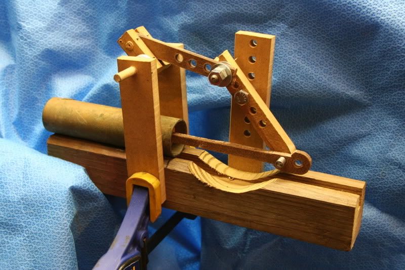
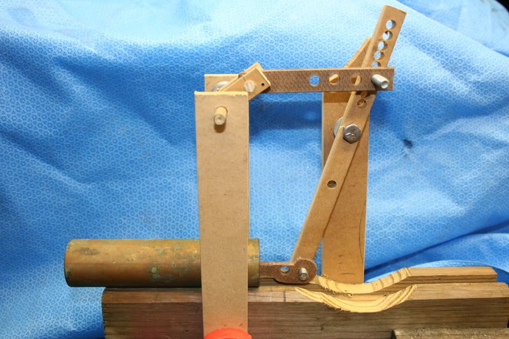
As promised, I have given this engine quite a bit of thought. It was obvious it was going to be long and spindly looking. After much thinking and a couple of nightmares, this is what I came up with:
Gentleman, meet Funky.
A horizontal gasoline beam engine.
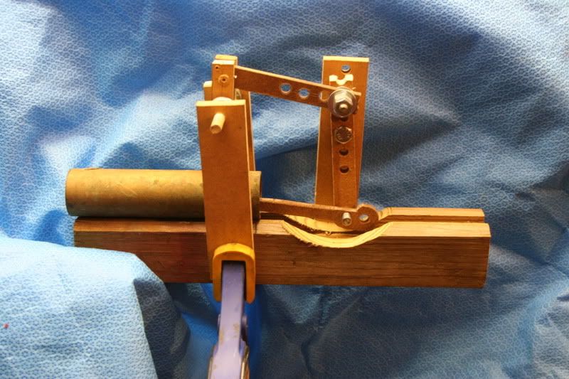
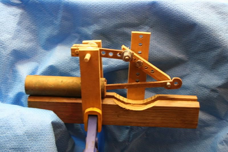
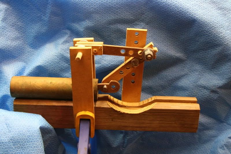
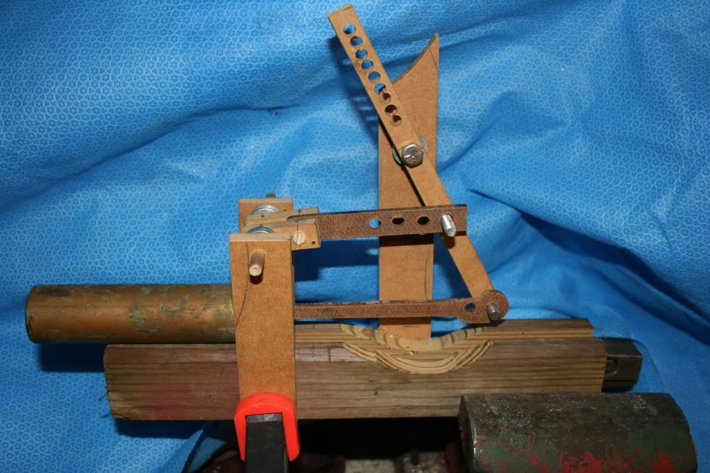
A few more photos of the engine as it goes through one rotation.
The bore is 1 1/8", stroke 3 3/4", crank throw 3/4" (1 1/2" stroke of the connecting rod. Keep in mind this is the crudest of mock ups, done to get a feel of the concept. The rest of the engine would be totally conventional, with the exception of the auxiliary exhaust. Any ideas or comments?
I have mentioned this before on this forum and I am attempting to tie up all the loose ends, but I am the grandson of Hamilton Upshur and I have been working with my Aunt to redo the website where his plans are sold. Tripod is quite dated and the advertisements just make the site unreadable. In the process of fixing this the website has moved locations
UpshurEngineWorks.com
this is the new web address for Upshur Engine Works. you will notice it looks identical to the old site, minus the nasty ads. Hopefully this will continue to suffice as I work as hard as I can to put together a new and improved site.
If anyone knows any other place on the internet where the old web address is still advertised can you please change it or bring it to my attention. I can be emailed directly at [email protected]
After further cogitation, I really like the idea of balancing the engine using reciprocating weight rather than rotating weight. How about using the "lever" engine design, but with a counterweight on the end of the beam?
Any thoughts on which design would make the most interesting engine?
Looks better to me. With the first setup, the flywheel is quite up in the sky. The second one looks more natural.
As it is now, stop playing around and make chips!
Looks better to me. With the first setup, the flywheel is quite up in the sky. The second one looks more natural.
As it is now, stop playing around and make chips!
There's only one problem with making chips: I have no idea how I'm actually going to make the thing. So far, this has been an exercise to determine proof of concept and gain some idea of proportion. In fact, I'm thinking I will have to pursue a wooden mockup a little further, something that is actually made to predetermined size and conformation!
Unless, or course, someone comes up with drawings.


")