You are using an out of date browser. It may not display this or other websites correctly.
You should upgrade or use an alternative browser.
You should upgrade or use an alternative browser.
Line-Shaft Clutch
- Thread starter Brian Rupnow
- Start date

Help Support Home Model Engine Machinist Forum:
This site may earn a commission from merchant affiliate
links, including eBay, Amazon, and others.
Herbie--Don't rush in where angels fear to tread----You are going to have your hands full getting your first engine to run. By the time you get to that stage, I'll have figured out whether or not this clutch is going to work.---BrianI am getting a strong urge to make this attachment for the Rupnow vertical engine.
-If you go back and look at reply #8 you will see that on the original line shaft clutches, the tapered bits on the end of the arms have a thread in them. I think that was how they adjusted to compensate for wear and to make sure that both arms extended equally. Of course, here in "Model world" I don't have to be quite as concerned with wear. Now that I have actually made the arms, I see that I could have incorporated a threaded fastener into them to provide the same service, however, as in most things I build, this is my 'prototype", even if I never build another one. Before this week, I always wondered about this type of clutch and how it actually worked. But----There are about a million mechanical things floating around in the back of my mind that I kind of wonder about, but unless I make a conscious effort to recreate the design and build one myself, they are only vague thoughts. One thing I can say for this clutch, based on my experience so far---There isn't much "between" to this clutch. It's either ON or its OFF. Probably it transfers less shock to the driven machinery than a dog clutch would, but there isn't a whole lot of "slippage". There doesn't seem to be any replaceable lining on the friction shoes either from what I can see in the photograph in post #8.
My clutch is all finished and seems to work well. If I can find the energy to get things set up, I'll post a video. I think since I already have my Kerzel hit and miss out on the bench I will use it as a driver, thru the newly made clutch, to the steel ball elevating staircase. If everything works as I hope, I will put up a link to the drawings.-- Most line shaft clutches I remember seeing had the line shaft overhead, and a long handle that hung down for the machine operator to pull to engage the clutch. Of course my memories are from sawmill stuff in the 1950's.---Brian
Brian
if your bored and want to go for a few hour drive down towards Sarnia, head over to Petrolia On and check out Baines Machine and Repair. He still runs almost his entire shop using overhead flat belt system.
http://www.hardoilnews.com/21863676
and
http://lostlambton.proboards.com/thread/33
Click on the second picture or the link below
http://s209.photobucket.com/user/lost_lambton_found/media/industries/65f81eb6.jpg.html
I used to hang out there a bit in my early teens. He's good friends with my dad but he probably wouldn't remember me (or at least I wouldn't expect him to). I stopped in a few years back when I was home and just stood and took in the whole overhead system again. So cool.
Well, I'm all set up and ready to go. I realized that the drive wasn't going to work on the Kerzel, because the gas tank was in the way, so I stuck the Rupnow Vertical in there instead. However, I've ran into technical difficulties. My clutch which worked so good when testing it in the lathe is letting me down in "actual circumstances". The coned hub which the lever moves back and forth is supposed to turn freely, so that when it is engaged it doesn't see any load from the lever. When engaged it is supposed to turn with with the central hub and arms. For some reason that isn't happening, and it is creating drag where there shouldn't be drag, and making my drive belts slip. I'm too tired to fight with it anymore today, so I am going to clean up, go upstairs, and drink wine.
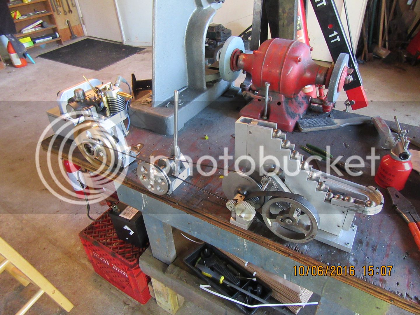

Right now I'm not too impressed with my clutch. In all my years in engineering I have never had particularly great results with sliding mechanisms. It seems that nothing has fundamentally changed. Pivots rule!! I will make one more stab at making my clutch work tomorrow. if I don't have immediate success, there is going to be a design change. I haven't lost all that much if I go to a total design change. The frame and pulley have the most work in them, and that will stay. I have to think on what to do next.---Brian
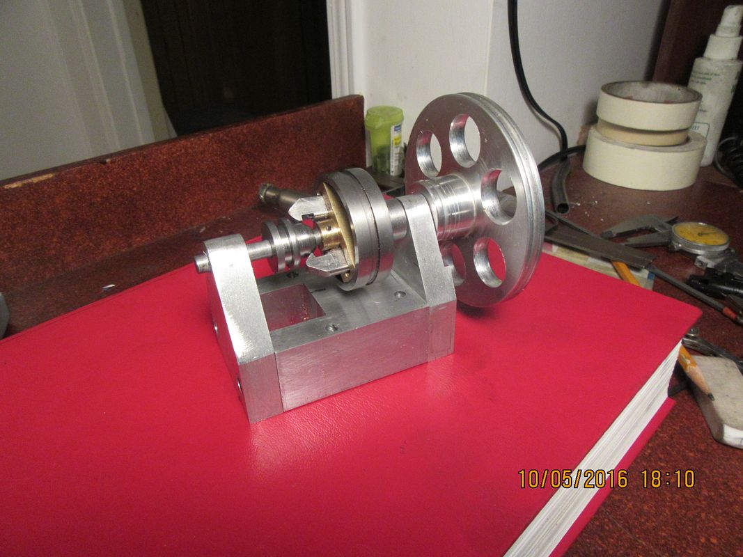
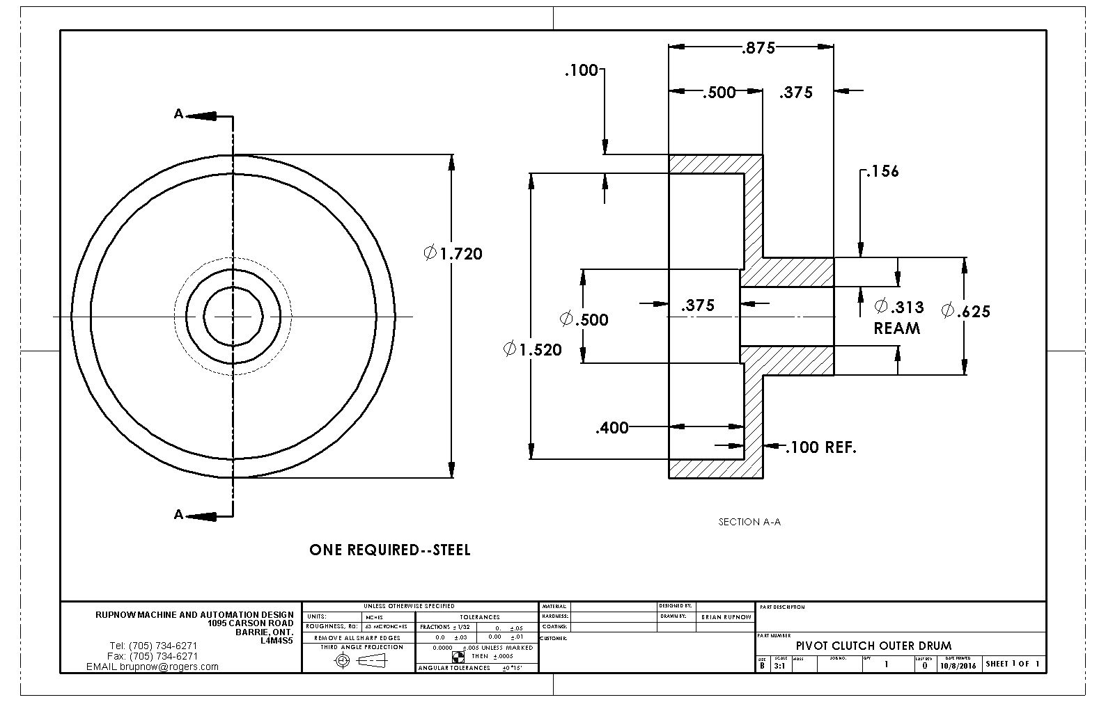
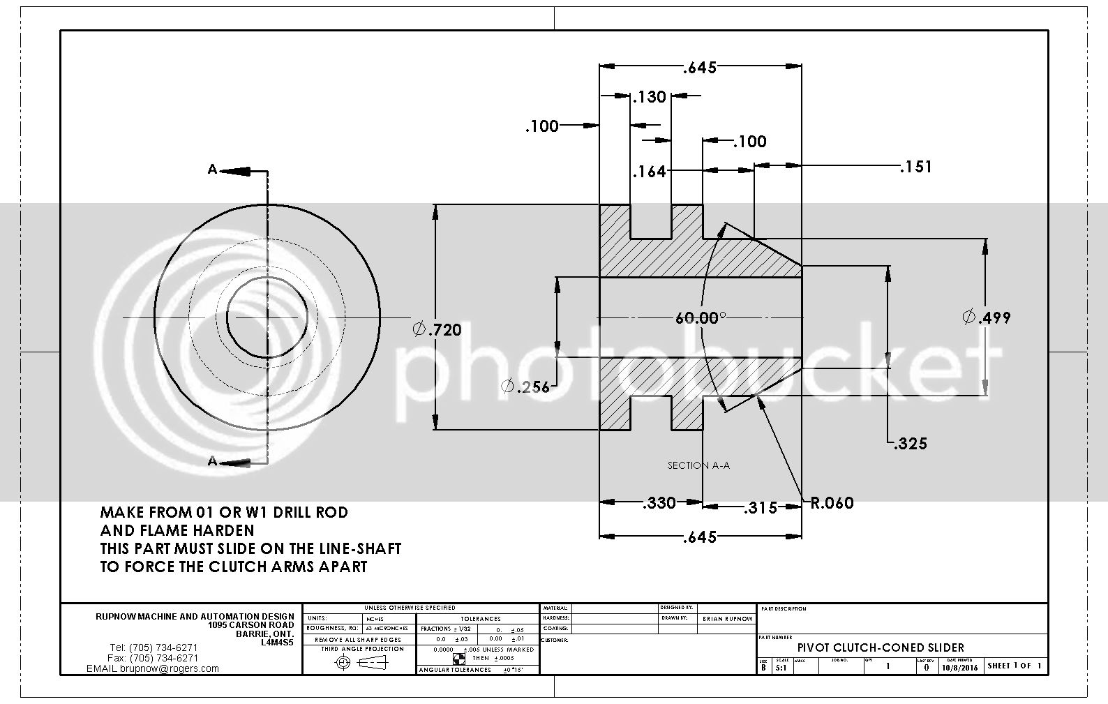
So there we have it--An operating line shaft style, expanding shoe drum clutch. This was not a great effort in terms of engineering, as I followed a design from long ago. The problems came in reducing everything in size to end up with a 1/4" shaft and a 1.7" outside diameter drum. The original full sized clutches had better proportions, and the contact surfaces on the end of the arms which the sliding cone bears against to operate the clutch had threaded ramps, which could be used to set the pressure on the shoes, and equal travel on each arm. My initial attempt to operate this clutch yesterday failed because there were too many points of "binding" in all of the mechanicals. I took it all apart this morning, added a few clearances to critical areas, and made a new coned slider out of O1 material which I flame hardened. That seemed to do the trick, and as the video shows, the clutch does operate.
[ame]https://www.youtube.com/watch?v=y5m5SrYTjFk[/ame]
[ame]https://www.youtube.com/watch?v=y5m5SrYTjFk[/ame]
Interesting project
Thank you for sharing, nice video
Michael
Thank you for sharing, nice video
Michael
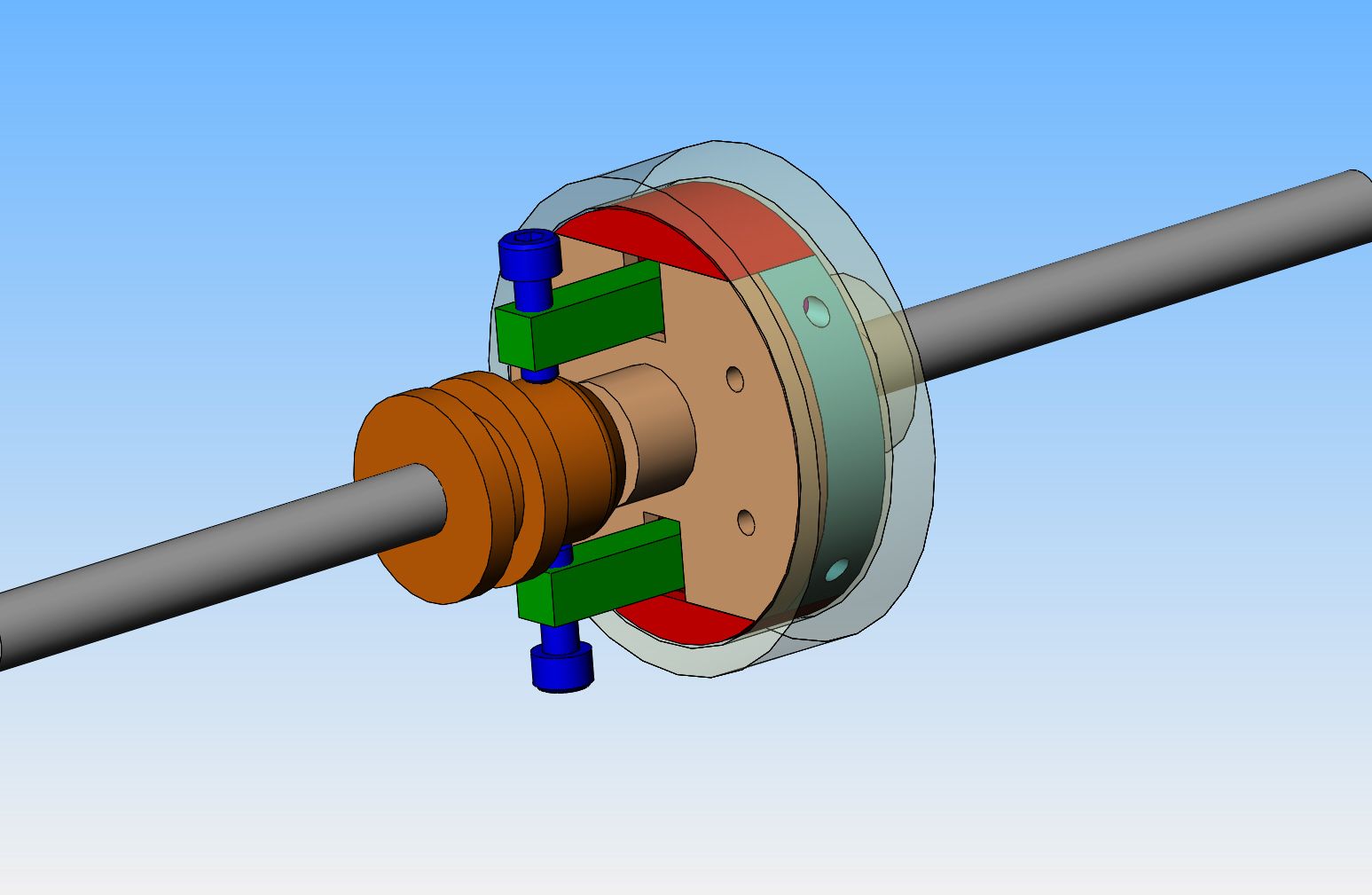
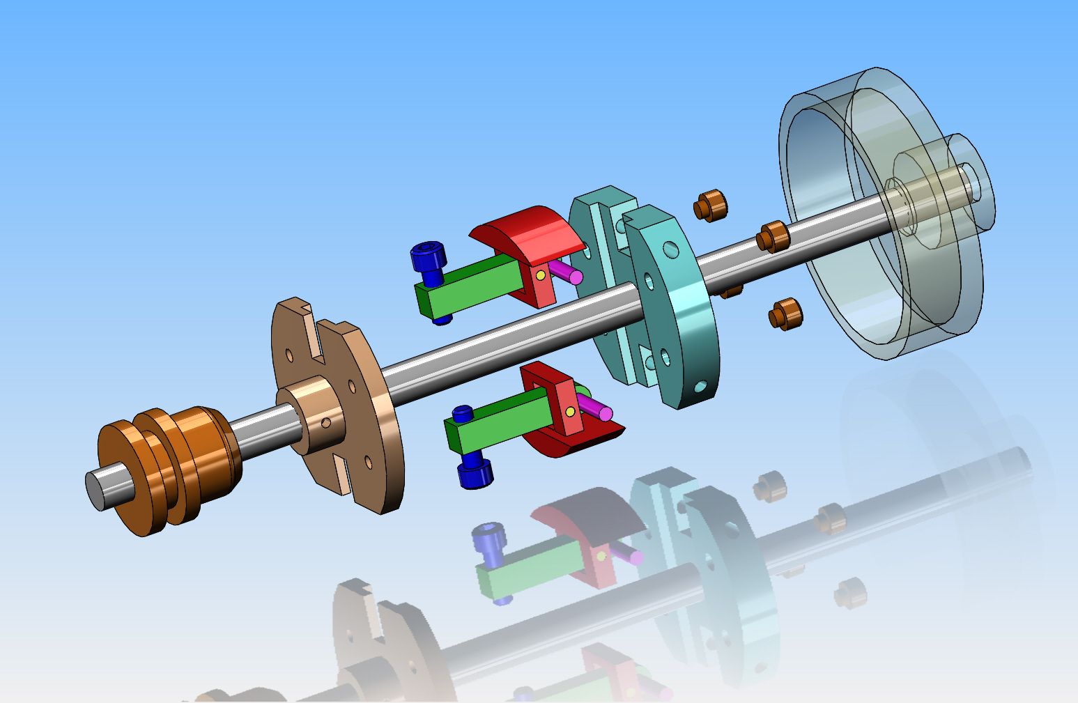
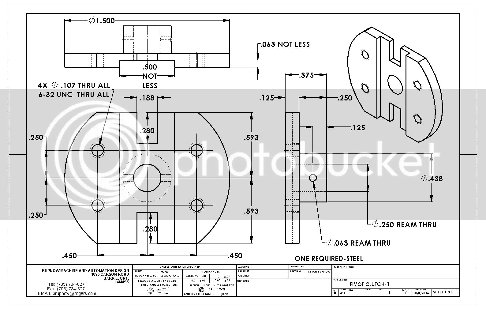
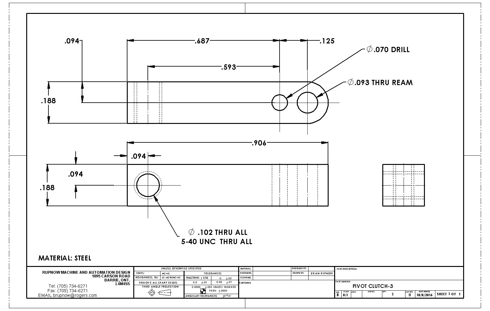
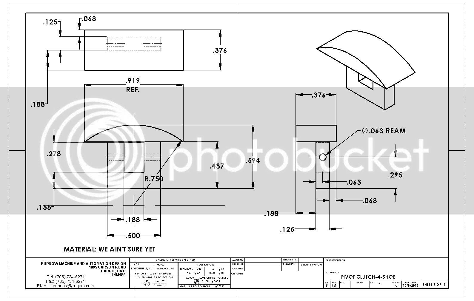
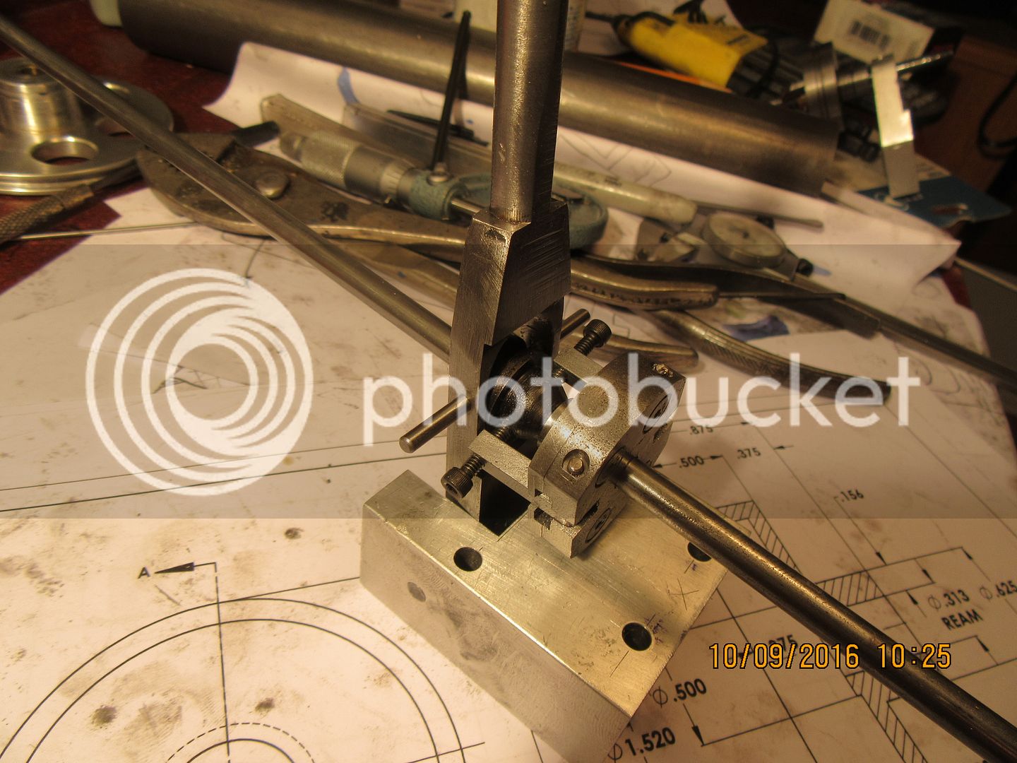
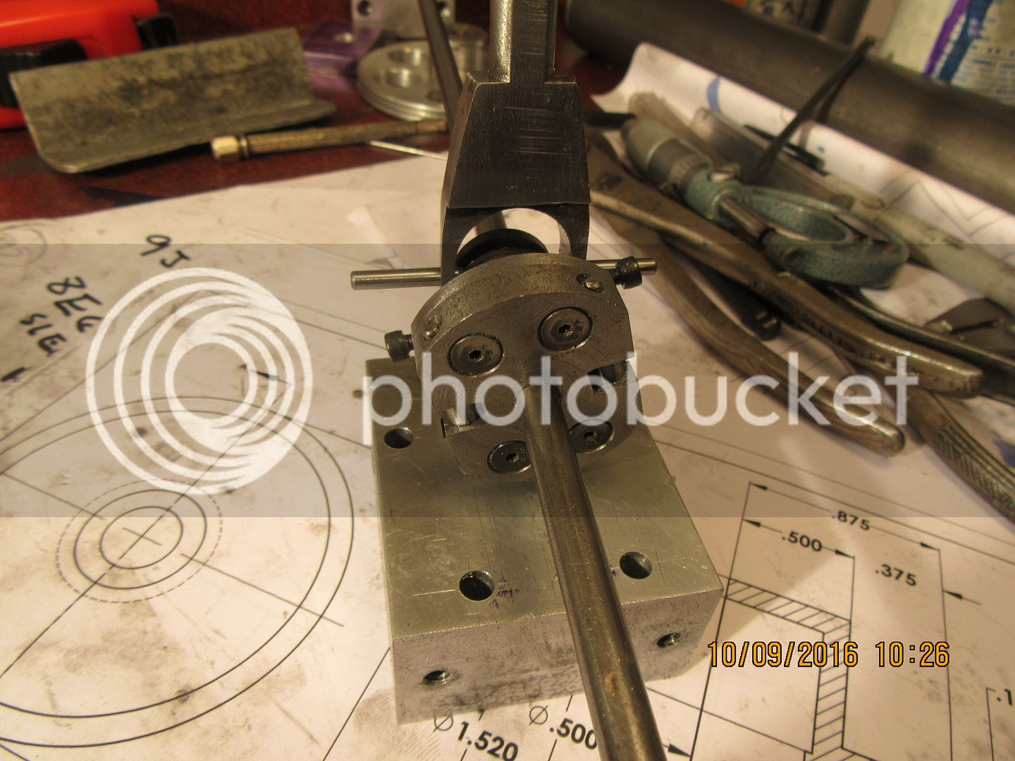
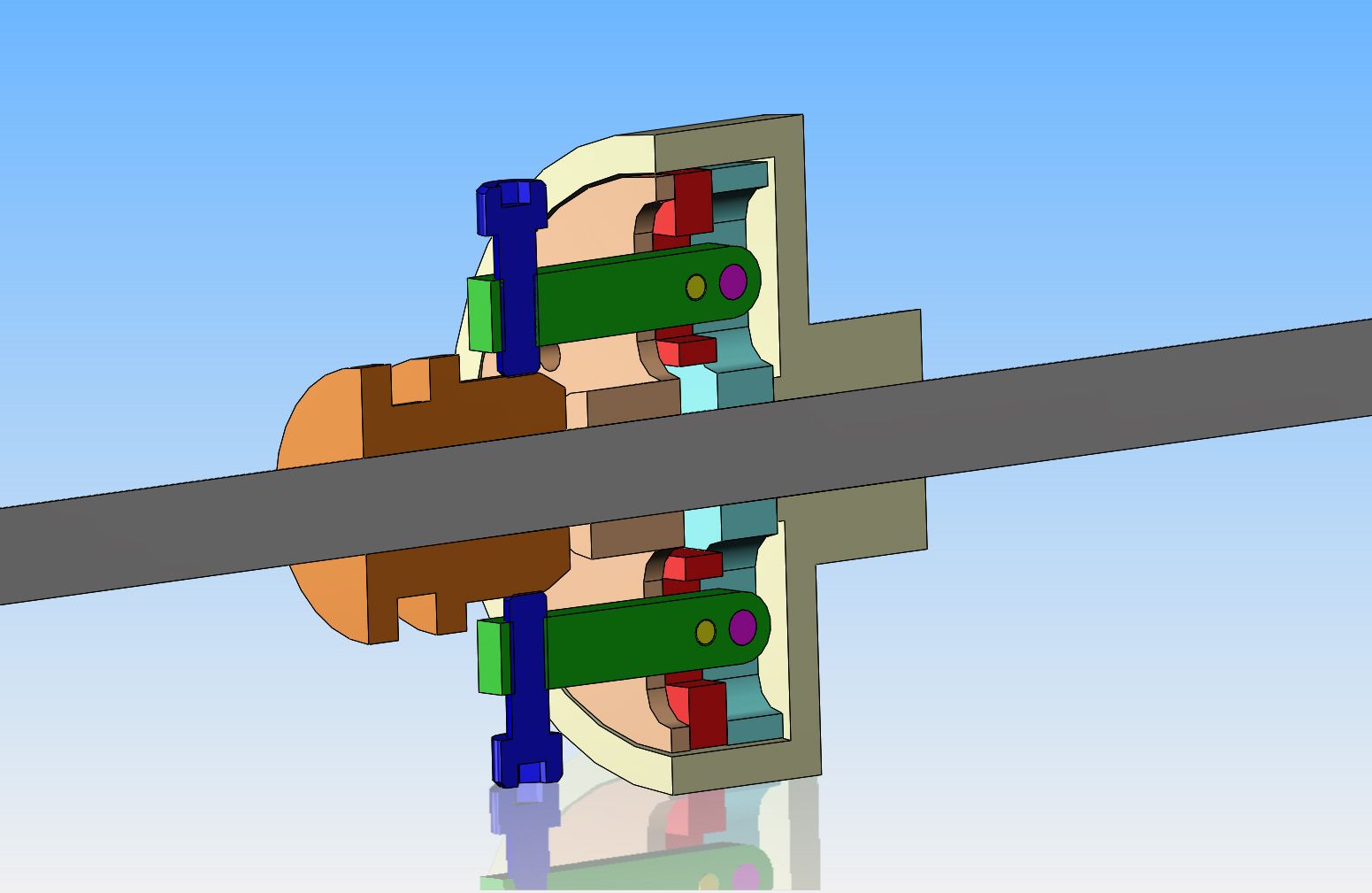
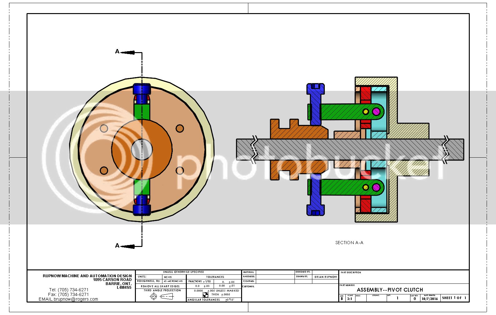
Having built one line shaft type clutch, which works, but is far from perfect (I hate sliding parts), I have taken some advice from Charles Lamont on HMEM and reworked the design so the clutch shoes are operated by pivoting levers. The shoes still slide in a milled rectangular slot, but the arms which operate the levers are pivoted at one end, and have an adjustment screw at the other end to set the pressure they exert on the inside of the drum, and the two separate sliding shoes can be equalized. Force is transferred from the pivoting arms via a cross-pin which transfers movement to the sliding shoes. The overall diameter is the same as the clutch which I just built and made the video of. I am quite excited about this design, and probably will make a clutch to this design in the coming weeks.


Belugawhaleman
Belugawhaleman
- Joined
- Jul 17, 2016
- Messages
- 4
- Reaction score
- 0
I've been wanting to make a clutch of similar design. Thanks for posting.
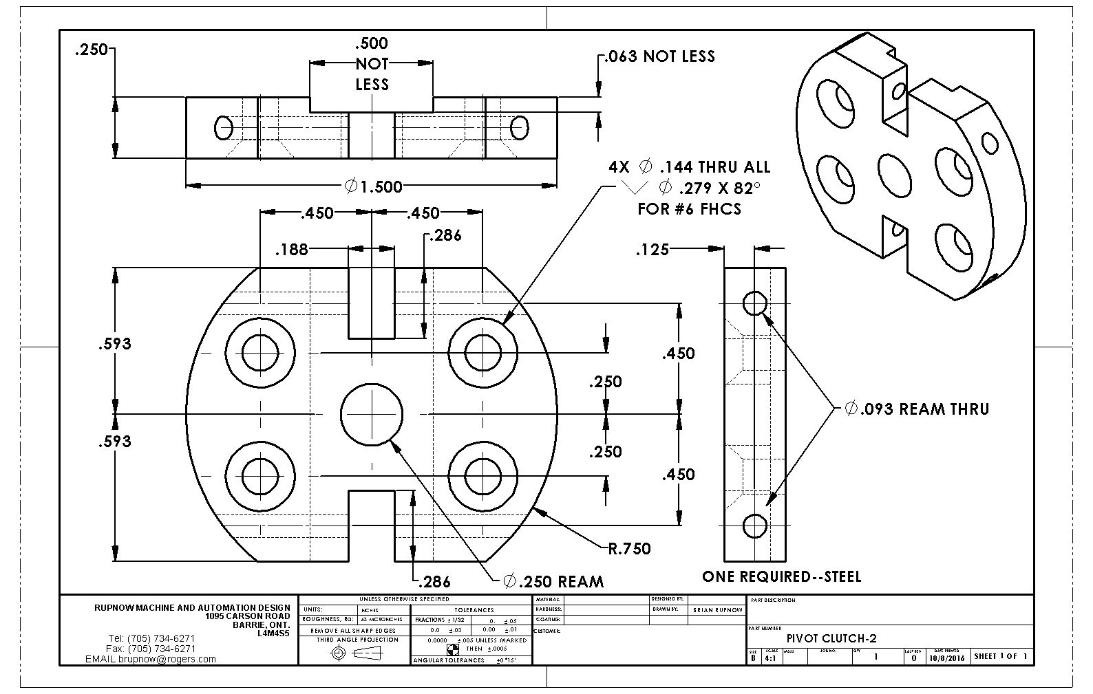
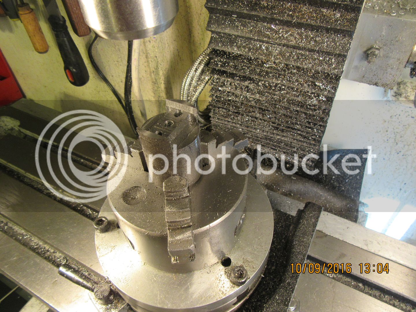
So, after a full days work, this is the new clutch in which the shoes are expanded by pivoting levers. I have one "in process" shot of the shoes being machined as one piece from a 1 1/2" diameter piece of steel. They were fitted and split into two pieces after all of the machining. It works so smoothly I had to make a movie of it.
[ame]https://www.youtube.com/watch?v=szABU_9WM4o&feature=youtu.be[/ame]

[ame]https://www.youtube.com/watch?v=szABU_9WM4o&feature=youtu.be[/ame]
Charles Lamont--If you are following this thread, thank you for your suggestion about the pivots in the mechanism. I have rejigged the mechanism to what you suggested, and it really does work much better than the way I originally had it.---Brian
And a short "explanation" video of the fully assembled clutch----
[ame]https://www.youtube.com/watch?v=lGXQXf7ZGSY&feature=youtu.be[/ame]
[ame]https://www.youtube.com/watch?v=lGXQXf7ZGSY&feature=youtu.be[/ame]
Similar threads
- Replies
- 44
- Views
- 8K
- Replies
- 0
- Views
- 1K


