Bernd
Well-Known Member
Here's an easy way to do layout work on small pieces. I'm no expert by any means. I hope to give the newbie an idea of how it's done. Comments welcome both constructive ") and destructive.
and destructive.
Here is some of the tooling required:
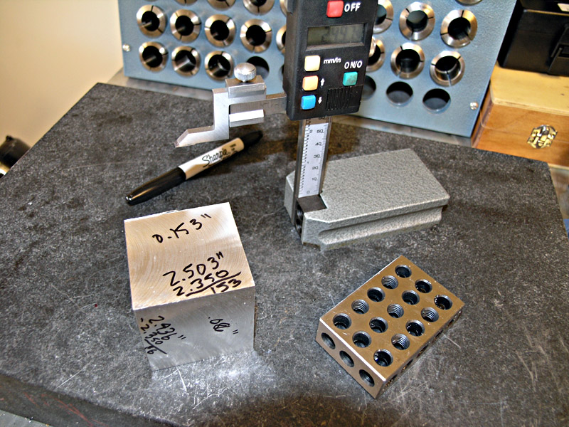
An angle plate
A block to raise the part up for easier marking. I'm using a 1-2-3 block
6 inch scale
A scriber (I don't know what the technical term for this tool is)

Next place the part your going to mark on the block along with the scale and set the sharp pointer to the correct setting. In this case it's 0.500" inch.

Next draw the sharp point across part to scribe the line.

Here are the two bases for Elmer Verburg's Wobbler almost all marked.

Here's an alternative to not having an angle plate. Since 1-2-3 blocks come in sets, you can use the two to create your own angle block.

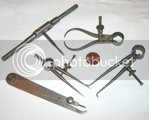
Once all the intersections of the holes are marked it's time to "center" punch the holes. In the picture below are three punches. The top is an automatic prick punch, next is one you need to tap with a hammer, and the third is a home made "center" punch. The difference between a "prick" punch and a "center" punch is in the point. The "prick" punch has a very sharp point so you can feel the point "drop" into the cross lines you have scribed. A "center" punch, which has 60 degree point, is then used in the "prick" punch hole to enlarge the dimple formed by the "prick" punch making it easier to center drill. In other words the large punched dimple will keep the center drill from wandering off the scribed line.

In the next picture I'm using the automatic prick punch to mark all the cross scribed location. Then I'll use the center punch to enlarge the dimples. The automatic punch works by pressing down on the top. When pressed down a spring is compressed to a certain point. The spring then pushes a plunger down hitting the top of the tip and a dimple is formed. It's kind of hard to explain it's action so think of it as having a hammer in side the hits the punch for you when you press down on it.

And here is what it'll look like. Not very impressive it's it? ??? But you get the drift? (pun) :-\

Tat Da. The finished base plates all center punched ready to be center drilled and drilled. ;D

Hope this will help a beginner who is a bit complexed as to how one can layout a small part as accurate as possible with some simple tools. The same will work for larger pieces. You'll only need some bigger tools.
Bernd
and destructive. Here is some of the tooling required:
An angle plate
A block to raise the part up for easier marking. I'm using a 1-2-3 block
6 inch scale
A scriber (I don't know what the technical term for this tool is)
Next place the part your going to mark on the block along with the scale and set the sharp pointer to the correct setting. In this case it's 0.500" inch.
Next draw the sharp point across part to scribe the line.
Here are the two bases for Elmer Verburg's Wobbler almost all marked.
Here's an alternative to not having an angle plate. Since 1-2-3 blocks come in sets, you can use the two to create your own angle block.
Once all the intersections of the holes are marked it's time to "center" punch the holes. In the picture below are three punches. The top is an automatic prick punch, next is one you need to tap with a hammer, and the third is a home made "center" punch. The difference between a "prick" punch and a "center" punch is in the point. The "prick" punch has a very sharp point so you can feel the point "drop" into the cross lines you have scribed. A "center" punch, which has 60 degree point, is then used in the "prick" punch hole to enlarge the dimple formed by the "prick" punch making it easier to center drill. In other words the large punched dimple will keep the center drill from wandering off the scribed line.
In the next picture I'm using the automatic prick punch to mark all the cross scribed location. Then I'll use the center punch to enlarge the dimples. The automatic punch works by pressing down on the top. When pressed down a spring is compressed to a certain point. The spring then pushes a plunger down hitting the top of the tip and a dimple is formed. It's kind of hard to explain it's action so think of it as having a hammer in side the hits the punch for you when you press down on it.
And here is what it'll look like. Not very impressive it's it? ??? But you get the drift? (pun) :-\
Tat Da. The finished base plates all center punched ready to be center drilled and drilled. ;D
Hope this will help a beginner who is a bit complexed as to how one can layout a small part as accurate as possible with some simple tools. The same will work for larger pieces. You'll only need some bigger tools.
Bernd