Involute gear cutter calculations in Metric

Home Model Engine Machinist Forum

Help Support Home Model Engine Machinist Forum:

This site may earn a commission from merchant affiliate links, including eBay, Amazon, and others.

DaveRC

Well-Known Member
Joined
Dec 4, 2010
Messages
83
Reaction score
4
Another gear cutting question.

I need to make a couple of small timing gears, a 60 tooth and a 40 tooth. I need to calculate the outside diameter of the gear blank and how deep do I need to cut..

Now, I have found a thread on here that explains all this in great detail and I understand what needs to happen, only thing I can't find the way of calculating this in Metric..!

I have 2 involute gear cutters, both in 0.5 Module, one cutter number 4, 26T to 34T and the other number 2, 55T to 135, so I thing (hope) I got the right ones, now just need to work out the size of the blank and how deep to cut.

Dave
 
I ran a 60 tooth, 0.5 module gear through my GEARSPUR program and got the following. Check the numbers for sensibility and, if they look OK, download the program and run the other gear data through it.


<C:\DOCUME~1\HP_ADM~1\Desktop\MWK> gearspur
mperial or (M)etric units?

Enter whatever data you know. Enter zero (0) for unknowns.
You must enter two data items to obtain an answer.

OD of gear [2.35 mm] ? 0
Number of teeth [45] ? 60
Diametral Pitch [20] ? 0
Module [0.7874] ? .5

Diametral Pitch = 50.8000
Module = 0.5000
Number of teeth = 60
Outside Diameter = 1.2205 in = 31.0000 mm
Pitch Diameter = 1.1811 in = 30.0000 mm
Addendum = 0.0197 in = 0.5000 mm
Dedendum = 0.0228 in = 0.5785 mm
Whole Depth = 0.0425 in = 1.0785 mm
Circular Pitch = 0.0618 in = 1.5708 mm
Tooth Thickness = 0.0297 in = 0.7540 mm

B & S cutter number used to cut this gear = 2
 
Brilliant, just the answer I was looking for, now downloaded onto the laptop.

Thanks again,

Dave
 
Yep, good deed done indeed... :bow:

And sorry just one more question that I forgot to include in the original question.

Two gears next to each other, how do you work out the distance between centers..? I am guessing you use the pitch diameter, in this case 30mm for the 60 tooth one and 30 tooth gear that according to the downloaded tool has an OD of 16 and pitch dia of 15mm the distance between the two centres of these two gears together would be 22.5mm ???

Dave
 
You are correct.

A very useful quick reference page is here:

http://www.engineersedge.com/gear_formula.htm

The absolute best reference on this stuff for HSM-types is Ivan Law's 'Gears and Gearcutting'.

Could I be terribly rude here and butt in and ask Marv. a question?

I have seen somewhere in a book I have how the range for each of the eight B&S cutters is calculated. But can I remember which book it is? Or do I remember enough of my high school maths to work it out? Unfortunately no to both.

I think it has to do with summing a (geometric? arithmetic?) series from 12 (minimum teeth used for cutter) to infinity and then distributing it somehow eight ways.

This is pure speculation, and I could well be talking nonsense but I wonder if it has anything to do with relationship between the radius of curvature of the involute and the number of teeth? For a small tooth count, it's a small roc and hence its inverse is quite big; for a large tooth count, it's a huge roc and its inverse is very small. If you sum the inverses of the roc for 12 & 13 (two gears), it comes to a fixed quantity. For large tooth numbers, you will need a lot more than two gears to get the same sum.

Can our resident professor shed any light? Or our resident psychic tell me which book it's in?

Many thanks.
 
djc,

I can't answer your question directly. It seems fair to assume that a more rapidly changing radius would limit the number of gear teeth one cutter could approximate. However, the mathematical distribution of the errors among the cutters is beyond me. I can't imagine any machinist being able to cope with the intricacies of *any* mathematical series. Perhaps if they were designed by an engineer?

Or perhaps it was the ever popular TLAR process?


TLAR = That Looks About Right
 
djc,
I did a little bit of a light duty analysis on making gear cutters and the series of cutters. It is covered beginning at:
http://www.homemodelenginemachinist.com/index.php?topic=10449.msg114810#msg114810

There are a couple of Excel spread sheets attached. I I did a curve fit for the series of 8 cutters and concluded that the B&S people used some fudge factors to even some of them out to work with integers. You can extract my equation from spread sheet as it is unprotected. Does not agree completely with B&S but was close enough for my purposes.

Gail in NM
 
Go to this link and download and install 'GearSpec'. It caters for all types and sizes, imperial and metric.

http://www.wmberg.com/Tools/

Input your data, and forget about your name etc. just press calculate.

Within a couple of seconds of starting, you should have most, if not all of the info you require.

40 teeth.jpg


60 teeth.jpg
 
Gear cutters are approximations of the correct profile and are typically an approximate radius not a true involute.

You would theoretically need a cutter per number of teeth but again they are clumped together within an acceptable error range.

The only way to get a true involute is by hobbing or shaping the gears to generate the profile.

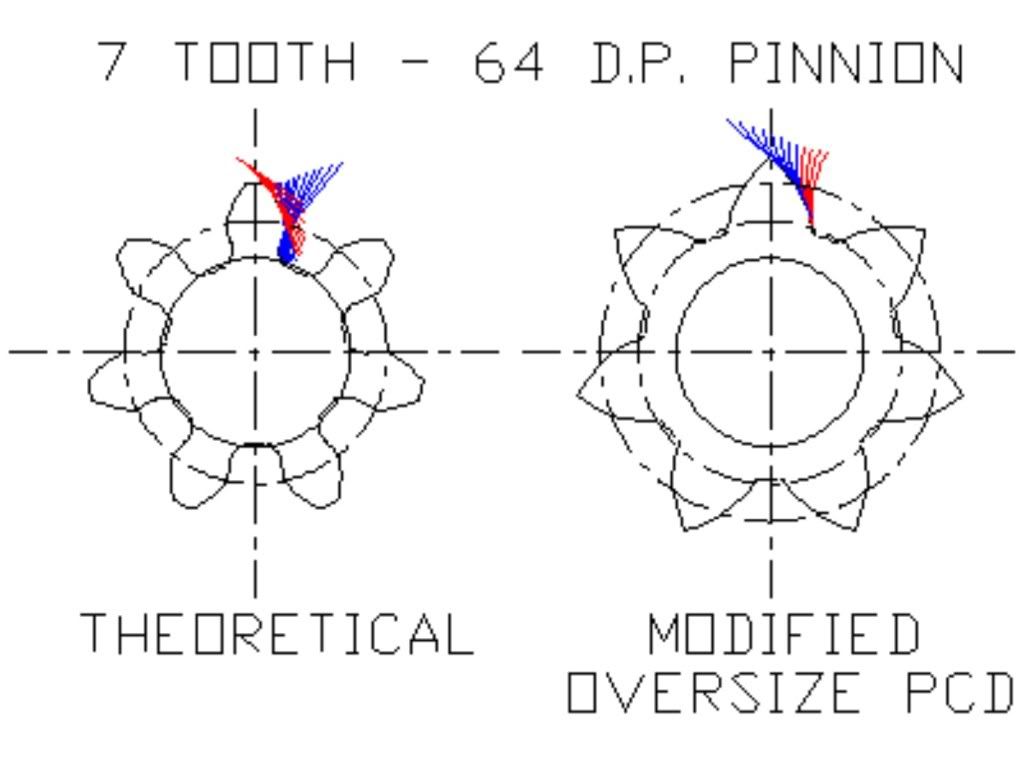
Tooth numbers below 12 become increcingly problematic - especially if you start dicking around with non standard pitch circles.

7t64dp.jpg


Even here a radius approximation works well if properly generated.

Ken


Bogstandard said:
Go to this link and download and install 'GearSpec'. It caters for all types and sizes, imperial and metric.

http://www.wmberg.com/Tools/

Input your data, and forget about your name etc. just press calculate.

Within a couple of seconds of starting, you should have most, if not all of the info you require.
thanks for the link.. some handy tools there.
 
Thanks guys, some very helpful info there, I think I have all what I was looking for.

One other question that came to mind.

When actually cutting the gear, do you cut to full depth in one pass or smaller cuts in several passes?

Dave
 
Take your choice really, conventional wisdom says cut in a single pass, but there are others who advocate gashing first and following up with a finishing cut. Both methods appear to work OK, but the gashing method does involve twice as much indexing (x2 the possibility of error)
 
Tooth numbers below 12 become increcingly problematic - especially if you start dicking around with non standard pitch circles.

fwiw: Undercut happens any time the number of teeth goes below: 2 / (sine PA)^2 (2 divided by ... the sine of the pressure angle squared).

e.g for 20° PA -- 2 / .34202^2 = 17.097 So anything under 17 teeth with a 20° pressure angle will have undercut.

 
Precisionm - yeah its a long time since I actually ran those calculations - I was refering to rules of thumb.

That I presume refers to "rack" cut calculations - what happens in conjunction with another gear of "x" teeth ?

When I run into interference problems (example 8:38 ratio 64 D.P. gears) I switch to generating the 8T with the profile of its mating 38T - this eliminates much of the interference.

You make gears for a living - comments ?

Regards,

Ken
 
Calculating the rule of thumb ;)

Anything under....

30° PA - 8 teeth
25° PA - 11 teeth
20° PA - 17 teeth
14.5° PA - 32 teeth

... will have undercut.

Yes... that is cutting to standard addendum/dedendum numbers whether generated via rack (Maag method) or shaper cutter (Fellows style). -- note that these numbers are specifically for gears being generated. All bets are off when a form cutter as used.

If the gear pair is one large and one small gear, the general method used to make the pinion stronger (i.e. reduce undercut) is to cut it oversize (in other words, on an oversize blank), and the cut the mating gear on an undersize blank -- which leaves the center distance the same. You can also just fatten up the tooth thickness on the pinion and thin it on the gear, which doesn't solve the undercut issue on a low tooth count, but still helps the pinion. Once again though, this pertains to cutting by a generated method. The form cutters that many people use with an indexer in a mill to cut gears will not produce the correct shape if used on an oversize or undersize blank.

I'm not quite sure what you mean by "generating with a different gear". A Fellows-style shaper "generates" with a cutter... (which is nothing more than a gear if you take a section through any point along its life). It doesn't really matter how many teeth the cutter has (within reason) -- the gear being cut will look exactly the same. I could shaper cut a 10 tooth pinion with a 10 tooth cutter, or cut it with a rack (essentially a gear with an infinite number of teeth), and the gear being cut will turn out the same.

Yes... I "sometimes" make gears for a living. I've been around gear cutting tools and gear cutting my entire life -- but it's not the only thing I do. I have a #7 Fellows in my shop, but almost everything I do relating to gears gets done via wire edm. It's my weapon of choice. :)

PM
 
What I meant was theoretical generating via autocad - using the larger gear profile as an imaginary Fellows shaper.

I start by generating the larger gear profile from a rack a'la Maag and then use that shape to generate the pinnion a'la Fellows.

At the end of the day the profile is a radius approximation (or a series of two or three radius approximations) of a true involute.

I then go the wire EDM route with the data.

I see you use a software package - does this generate true involutes or approximations ?

I briefly worked for ZF making truck gearboxes.

Ken
 

Latest posts

Back
Top