IH Mill CNC Conversion

Home Model Engine Machinist Forum

Help Support Home Model Engine Machinist Forum:

This site may earn a commission from merchant affiliate links, including eBay, Amazon, and others.
Bob, I converted an RF40 a couple of years ago, I searched as many sites as I could for info, photos and links and eventually figured it out. Is there more info "out there" now to help others? I always thought that if someone put together a guide to help others through the rough spots a lot of others would make the jump to CNC.
With regards to your conversion, did you make or purchase the mounts? I had a really difficult time devising a system to raise and lower the Z axis and eventually settled on spinning the ballnut to control the spindle. What are you doing mechanically for the Z? -Mike
 
I spent a few minutes on your blog this afternoon, a ton of good info there. In just a couple of minutes I saw several things I can incorporate on my mill. I really liked the wishbone guide for the round column. I'll have to spend a lot of time reading your blog to catch up on progress over the last couple of years. -Mike
 
Guys, sorry to be slow to respond. I had a virus on my PC that strangely made HMEM seem like it was down. Had to get rid of it before I could even get on here!

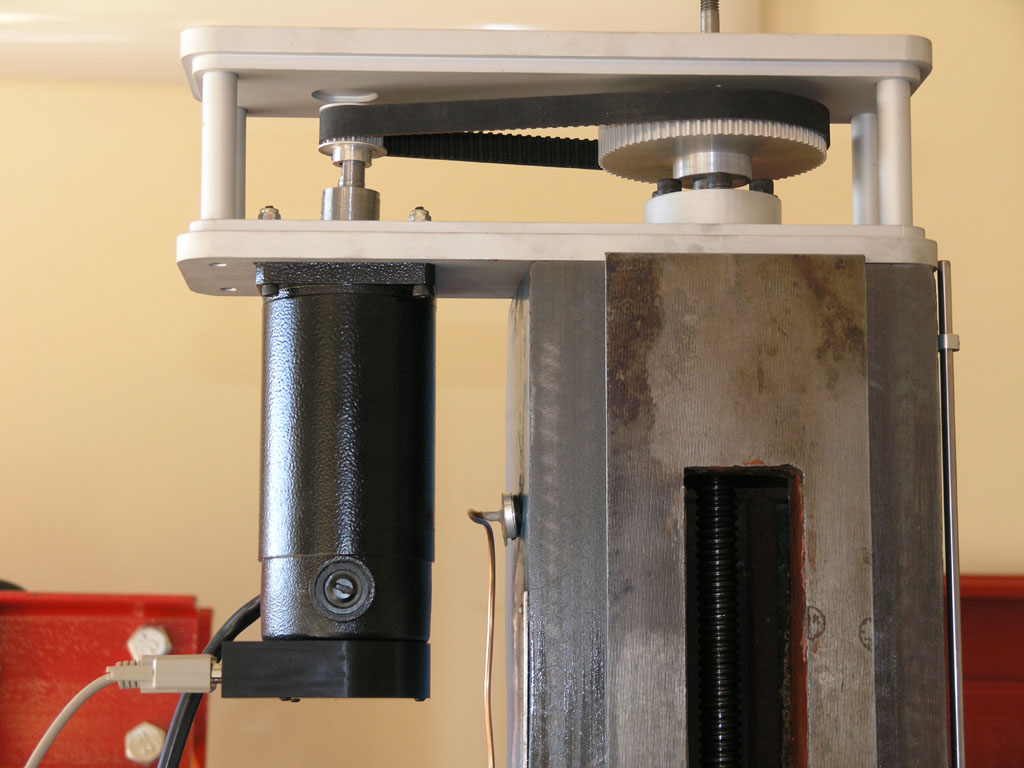
Anyway, SmoggyTurnip, those motors are servos, not steppers. Steppers make torque down low, they're all done by maybe 1000 rpm. Servos make their torque up high, at say 3-4,000 rpm. So you have to gear them down. One useful advantage in doing so is they can obtain very high resolution. Mine measure 2000 counts per revolution x 2.28 ratio x 5 pitch on the leadscrew = about a half a tenth. That doesn't mean this mill is accurate to half a tenth! But, it does provide some useful benefit as we'll see when I get to talking about what I was up to this afternoon.

Holescreek, there is a lot of info out there on the Internet, but I've not seen any good one stop places to speak of. Most people either buy a kit, or they follow along what someone else did that has the same mill.

Okay, let's move on to the status report!

I got my Z-axis going with a shaft adapter I turned on the lathe:

P1011016.JPG


That adapter is apt to be temporary, as I want to re-engineer things so I don't have to extend the shaft so much. For now I just wanted to get running though.

I had an electrician out to the house to put in 2 more 220V circuits, one for this mill's spindle and the other for a big compressor I've been to get running soon. I had my brother over and we were all set to mount the spindle assembly onto the column when we discovered some vital hardware was missing.

Darn!

Tore apart the shop to no avail, so I placed an order with McMaster Carr for a new set of square head bolts. I probably could've turned a set too, but decided to order instead.

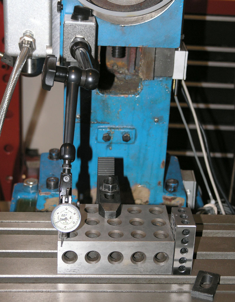
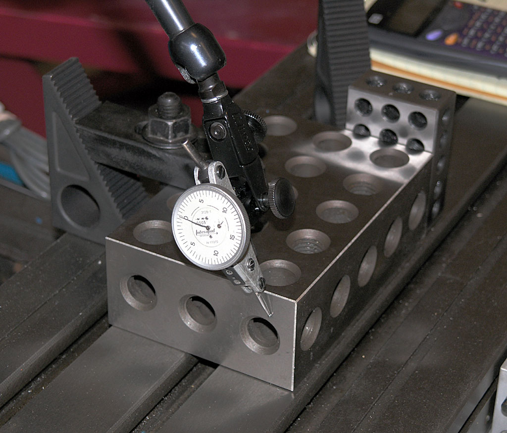
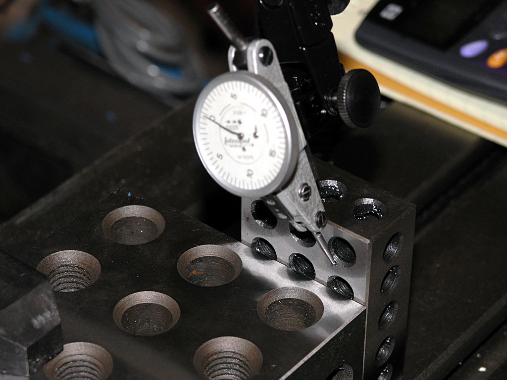
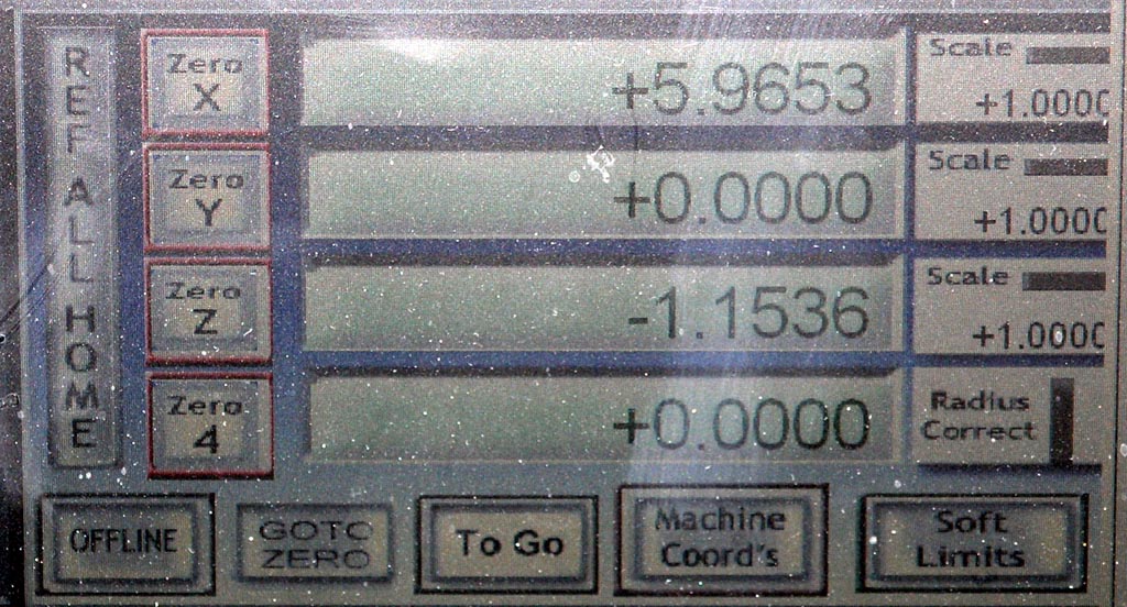
Meanwhile, since we couldn't mount the head, I decided to calibrate my X and Y axes and measure their backlash.

This is a really cool thing you can do with CNC. Essentially, you measure the travel of an axis with high precision, see how far the CNC thinks it traveled, and enter a "fudge factor" until the two match. You can get things extremely close, to a few tenths in fact. It's surprising how much the tolerances on leadscrews, even these rolled ballscrews, timing pulleys, and the like, can conspire to make things less accurate than you would expect. Before calibrating, I was using a calculated ratio based on the specs of the screws and pulleys. That was good for 0.001" approx, but much better could be had.

Here is how I did it:

First step is to find your length standard. I grabbed a 2-4-6 block. Longer is better because it gives more distance for an error to show up in. I wanted to measure my block, not having any idea how accurate it might be. So, I grabbed several measurements. I used my height gage, 6" micrometer, and 2 Mitutoyo digital calipers I had on hand. I then calibrated each of those with my 5" micrometer standard to be sure they were accurate. I threw out the outlier: the height gage was only good to a thou. Need to get a better one!

When I was done I discovered my 2-4-"6" block was a 2-4-"6.0014" block!

 
"Ground to 0.0001" my hat!

Anyway, now I know.

Next I clamped the block on the mill table and trammed it in just like you would a vise:

P1011017.JPG


It's so nice to tram on a CNC. Everything moves so smoothly. Zero at one end, jog to the other, tap until zeroed, tighten, recheck, it's dead on--sweet!

That block needs to be aligned with the axis that will travel so the distance you measure is not some diagonal of the block.

P1011018.JPG


Next jog until the needle bumps and then zero it on the dial. This is one end of the measurement. From here on out do not reverse the direction of the axis or you'll be letting backlash interfere with the measurement!

I raised the head to clear the needle, and set out jogging again...

P1011019.JPG


There we are touching off a 1-2-3 block I'm using to locate the other end of the 2-4-6-and-a-bit block. Precisely jog without changing direction at all until the needle on the indicator is at zero again. That would be really hard to do with handwheels!

:big:

For those who haven't played with it, Mach3 has several ways to aid you in such precise motions. You can control the jogging speed. I would turn it down to 5% when I got close. That's about 6" per minute on my mill. But you can also do "step" jogs. Each time you press the arrow on the key board, the axis moves one step. And you can change the step size: 1.000, 0.100, 0.010, 0.001, and 0.0001. So I'd get even closer stepping by 0.001, and then switch to 0.0001" (jogging by tenths!!!) until that needle was exactly right.

Now you can read off the "DRO" how far the machine thinks it moved:

P1011020.JPG


See the X says 5.9653" and it should be 6.0014". This one is off quite a bit! I checked the values and discovered I'd been fiddling, so this wasn't using the calculated values. I'd made things a little worse. But, it was no problem to dial in the right correction factor so it should come out 6.0014". I tried it again and hit it bang on. Very nice! We'll have to revisit on another day at another temperature. I'm sure it will no longer be accurate to a tenth, but I bet its better than a thou.

 
The same thing was done for the Y axis with similarly happy results. Now my mill is calibrated, at least for 2 axes.

What about backlash?

That's easy to measure while you're set up for this calibration work. Just bring the indicator up to an edge until it ticks. Zero it. Zero the DRO. Back off an inch, reverse direction, and jog until the indicator reads zero. You can read the backlash off the DRO.

This was a case where being able to jog in tenths was really helpful. It was fascinating to watch the needle on the Interapid indicator moving precisely as I punched the arrow key on the computer keyboard each time.

I found I had 0.0003" backlash on the Y axis and 0.0006" backlash on the X axis. I suspect I might be able to adjust a little of the X backlash out by tweaking the preload on the ballnuts.

That's all for this weekend, folks. Got a pot of special chili to finish up and some guests coming to enjoy it.

Cheers,

BW
 

Latest posts

Back
Top