Help me machine this connecting rod....

Home Model Engine Machinist Forum

Help Support Home Model Engine Machinist Forum:

This site may earn a commission from merchant affiliate links, including eBay, Amazon, and others.

deere_x475guy

Well-Known Member
Joined
Oct 26, 2007
Messages
900
Reaction score
13
Location
Eaton Rapids MI
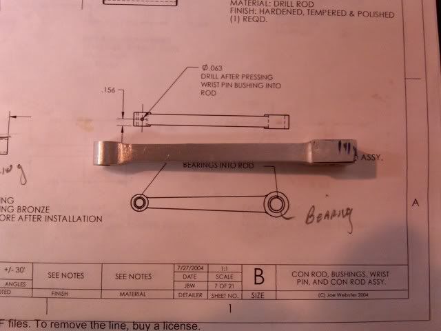
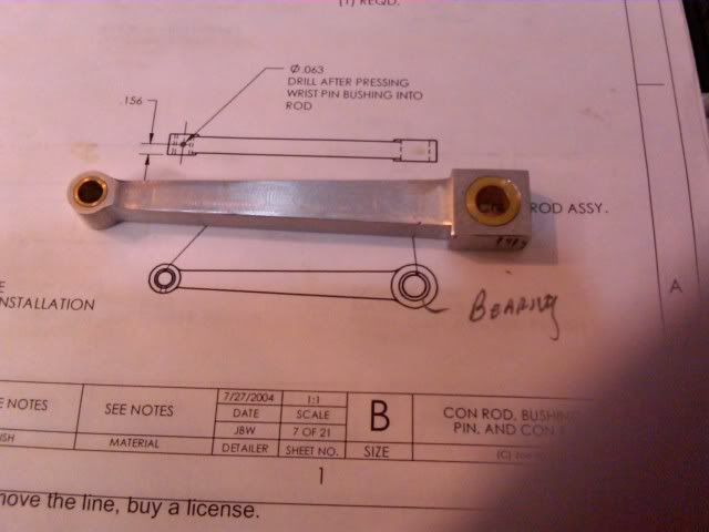
Hi everyone, I need your help here. I am going to machine the connecting rod next for my Webster engine. I am having trouble getting it in my head how I am going to machine this part. I have looked at the plans dozens of times and just can’t picture what I am going to do with it. I have a rotary table, and figure I will be using it and the mill. Or face plate on the lathe? Or a combo of both mill work and lathe work. How about posting some ideas to help my lost thinking out here? Any pics of set-ups, work holding or drawings will help, because in spite of this mental block I am a visual kind of guy.

Here is the page with the connecting rod drawing.

connectingRod.gif

 
Drill/ream the two ends holes to size. Do the round parts in the rotary table. For the tapers, insert a .125 dowel in each end hole and clamp the part with the dowels flat on top of the vice jaws and machine one side. Flip and machine the other tapered side the same way?

That will get it close no?

Eric
 
Julian,

Sorry, I don't do video. While I have a still camera, I'm too much of a throwback to have ventured into video.

Operation is pretty simple. Drop part over pin of correct size, set stops as needed, then advance work slowly into rotary file cutter while swinging from stop to stop to remove material. Observe safety restrictions - no gloves and, if part is so small as to bring fingers close to rotating file, use a clamp/pliers/etc. to keep hand out of action zone.

BTW, my name is Marv, not Mark.
 
Marv, Thanks for the additional info...Sorry about the name mixup I have no idea in %$*& where I got Mark!!!
I don't want to hijack the thread but I also have a question about the rod end. I understand how you would round one but what or how do you get the more than 180º effect?? ie, you do not want the rod end radiused to the long part.

rodend.jpg


Thanks, Julian G.

 
Julian it's all good, after all I did start this thread to learn a few things and hopefully others like you will ask questions also. Right now I am pondering using both Marv's and Eric's suggestions.
 
Here is how I made my Con Rods My method involved Mill work only.

First I crated a fixture to hold each rod on my Rotary Table. The fixture was a rectangular plate with Two Mounting Pins matching the location of the Wrist Pin and the Crank Pin. Since the Crank Pin and the Wrist Pin have a different diameters, one of the mounting pins contained a bushing that allowed the Con Rod to be flopped 180 degrees and avoid recentering the Rod over the spindle for each end radius.

smallconnrod.jpg


Next I began making each rod by drilling the Crank hole, Wrist pin hole and a holes at the fillets. A DRO is very helpful here. BTW when I calculated the position of fillets (I used a CAD Program but it could be done with Trig) I figured the Angle of the taper in the Shaft. In my case the angle was it was 3.12 degrees.
Next I Mounted Conn Rod on the RT and used a wobbler to center over the center (the Radius Point) of ONE of the mounting pins. The rest of the work involved offsetting the cutter for the particular radii then flopping the part 180 degrees and maching the other radius.

If you align both pins (radii) on the x axis, you can set your taper angle on the RT and trim the tapped sides. Or you can scribe a line fillet to fillet and use your wobbler to align the RT Angle to match the scribed line.


Smconrod2.jpg


BTW The Third Rod from the Left was scrap. I made 6 to get 4.

 
Julian Garrett said:
Marv, Thanks for the additional info...Sorry about the name mixup I have no idea in %$*& where I got Mark!!!
I don't want to hijack the thread but I also have a question about the rod end. I understand how you would round one but what or how do you get the more than 180º effect?? ie, you do not want the rod end radiused to the long part.

Thanks, Julian G.
Over on the MEW site, I ran across a rod-end-rounder like Marv's, but turned so the rod rotates on a horizontal pin and the end of an end mill does the cutting as the rod is swung to and fro. http://www.modelenginenews.org/restored/conrods.html


All good info. Its kind of funny that you need to spend hours searching the web for all of the good info. like this which doesn't leave much time to put it to use!!! I know I gotta LOT to learn!!!
Thanks,
Julian G.
 
jpaul, nice work.

in general, on connecting rods, whether they're IC like that or for steam valve gear, you will notice that there is almost never a sharp inside corner on the full size prototype. The reason is this creates a stress riser, a place where there is a high concentration of stresses and where failure will occur. Now our models aren't subject to the same stress and cycles but you will very much improve the appearance if you follow this full size practice like in the rods JP has shown. It's easily done, but requires a few more steps. Basically the fillet is put on with a ball end mill and then you have to offset and pic up the cut with a straight end mill. Or what i usually do, mill away everything except for the fillet area and put it on with a ball end millafter - the less material you're removing with the ball end mill the better.

Might be tough to do on yours Bob as it would required a 1/16 ball end mill to put the right fillet it, not sure I'd bother.....but i thought it worth mentioning in the general context of rods. It's these details that can really improve the visual appeal of an engine and is really required if the engine's a model.

 
Mcgyver,
I don't get the fillet idea. Could you do a pen sketch?
Hilmar

Basically the fillet is put on with a ball end mill and then you have to offset and pic up the cut with a straight end mill.
 
sorry if the explanation was confusing, basically that this,

connectingrodwithfillet.jpg


because its the right way to engineer the part, more closely represent prototypical practice and hence and makes for a better looking model than this.

connectingrodnofillet.jpg


As you can't effectively remove all the material between the bosses with a ball end mill, you need to do two passes on the RT....one with an endmill that is offset by the ball end mill radius, and then one with the ball end mill to put the radius on. its a few extra steps, but its not difficult as its all done while at the same set up.
 
YES!!!!!

This is what I was hoping to get rolling here. Lots of great discussion and pics/drawings with different ideas. Thanks guys!

jpaul thanks for taking the time to post the pic of your rotary table set up and an great explanation of how to do it.

Mcgyver, I am going to try to get them looking like your drawings. Your right about the tiny ball end mill, it might be a little tough to get done. Guess we will see how many I break ???
 
Yes, Mcgyver I got it now.
Nice Pix. I wonder if you could take an old end mill or a new one and round over the flutes to a slight radius. This way:
1.) you don't need a ball end mill and
2.) you could mill in one set up
I have to look in to that now. Just like the two start thread. Just a challenge. BTW I like to see Bob to make that threading tool out of Carbid.
Hilmar
 
I'll never say to you again what can and can't be done - its like giving you marching orders to go do it. ;D

I've seen end mills ground like that, it might be tricky to get an even curve. stone so you get a smooth surface on the work. I've got a small collection of ball end mills that don't see much action except for that sort of thing so haven't tried and with such infrequent use they last a loooong time. I thought about building a radius grinding attachment for the T&C grinder, but fortunately checked myself. From now on a tool has to have duty cycle of at least 10^-8 to be worth making lol
 
deere_x475guy said:
Mcgyver, I am going to try to get them looking like your drawings. Your right about the tiny ball end mill, it might be a little tough to get done. Guess we will see how many I break ???

Buy more than 1 for sure!

I've played with 1/8" and 1/16" BEM's. They're somewhat delicate, but not ridiculously. They hate 3 things in my experience: chips, plunging, and runout. Keep a steady stream of air while cutting, avoid plunging, and make sure you use whatever rig on your spindle has minimal runout. I learned after breaking three that my ER32 collet chuck (a cheapie!) had too much runout, while my R8 collet was fine.

I would think that last filleting pass isn't cutting too much as so might go okay. Mcgyver is right, it sure makes a prettier rod!

Cheers,

BW
 
LOL, I broke both the 1/4" ball end mills I had when I was making Mcgyvers bender. I ended up doing as he suggested and made the follow block by drilling a 1/4" and cutting it in half. ::)
 
Hi deere guy

I use a system similar to Marv,s but I try to always use a left hand spiral, right cut end mill.
The left hand spiral causes a downward force on the part and wont pull it up off the pin, but you still need end stops to keep it from grabbing at the corners.

Ivy McNeil

Righthandcut.jpg
 
I know this is an old thread and I can't believe it's been this long since I worked on the Webster. I made the mistake of posting the build for this under different threads for each part so I am going to try to finish it up all in the thread.

I did finally get around to making the con rod and have the wrist pin end rounded. Later I will build one of the great rounding jigs I have seen and do the crankshaft end. This weekend I also made the rocker arm and here are some pics. Sorry I didn't take more pics of the process. I will try to do so with the rest of the constructing.
screwup-1.jpg


IMG00154-20090413-1731.jpg


IMG00153-20090413-1730.jpg


IMG00148-20090413-1546.jpg


I think the next part will be the cam.
 
Back
Top