Help making flywheels

Home Model Engine Machinist Forum

Help Support Home Model Engine Machinist Forum:

This site may earn a commission from merchant affiliate links, including eBay, Amazon, and others.
B

Bogstandard

Guest
I think I may have asked this before, but my brain has a very short retention rate at the moment, so sorry if I am asking again.

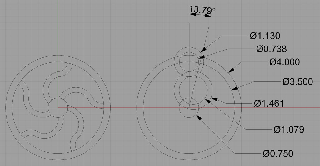
For a forthcoming, rather large project, I am looking for a method to make manually, using the RT, the wiggly spoke type flywheels that Wes has had such great success making using CNC and his own casting techniques.

No insults or ingratitude meant, but please do not point me towards magazine articles, as these are not available in the UK, unless of course you can scan and email.

There must be a method, but even though I am rather experienced in the use of the RT, when it comes to this problem, my mind blanks up.

I don't want to resort to building them up from individual pieces.

Any help would be appreciated.

John
 
Duclos or someone does this in one of the books, but as you say, you don't want a magazine article. So, how about this.

I drew a "wiggley flywheel" from circles in Rhino3D:

WigglyFlywheel.jpg


Here is the idea. You can construct your flywheel using circular cuts on circles whose centers are at 2 different radial distances from the center of the flywheel. I would think about building a fixture, not unlike a rounding over fixture, that makes it easy to do this. Here is an idea of where the pins would go:

WigglyFlywheel2.jpg


See? The symmetry is there. So you build the base of the fixture to sit at the center of the rotary table. The base has drilled and reamed holes for the dowel pins. The pin goes in the holder for the flywheel, which has a handle for you to hold while rounding over (or other arrangement). You'll need to drill clearance holes for the end mill to get started in, but that shouldn't be hard to lay out.

What say you, Mr. Bog?

A decidedly non-standard flywheel!

Cheers,

BW
 
Bob,

Thanks for that, my head is now starting to get round it. That does seem a rather simple solution.

That is exactly the style that is on my Atlas lathe for the main drive pulley.

Now to work out how to taper the spokes from hub to rim.

John
 
I think to taper you have to either change the radius or the center of the arc... I've not thought of a way to do either without moving the setup, but maybe something can be done with offset pins.
 
I'd change the center of an arc to taper. But you're really going to start having a lot of pins to fool with if each arc now requires 2. An alternative is to build the fixture as shown and taper with a file. I think the flywheel will look quite good even without tapering. It will certainly be something unexpected.

Best,

BW
 
I think that it' a great looking flywheel!, maybe you could file the outside ends of the spokes round tapering back to square in the centre, a bit fiddly I know but it would probably give the impression that the spokes were tapered.

Giles
 
Back
Top