Hand Tapper

Home Model Engine Machinist Forum

Help Support Home Model Engine Machinist Forum:

This site may earn a commission from merchant affiliate links, including eBay, Amazon, and others.
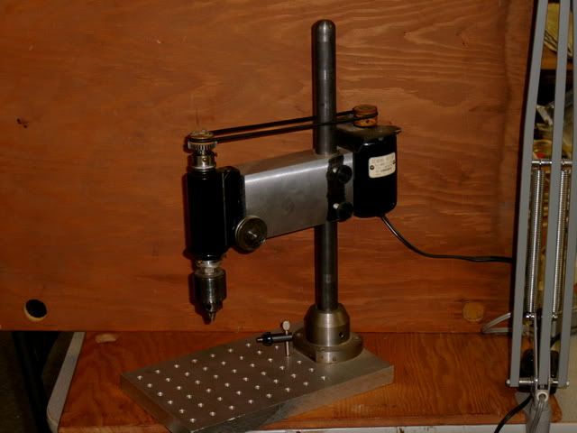
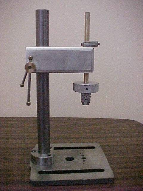
Wes, on the drill press handle, how about the idea of raising the table rather than lowering the spindle? Mcgyver and others have done that and it seems to be something's that's simple and works well.

What kind of speed do you plan for your spindle? Those tiny bits like a lot of rpms!

Best,

BW
 
Question. When using these Hand Tappers, how do you provide the downward force?
What I mean is, I have recently used my Drill Press to start taps straight. Holding down some pressure on the handle and rotating the chuck at the same time. Then when I want to reverse a quarter turn to break the chip, I have to let the down pressure off a little while I reverse it. Then back on with the down pressure as I advance again and so on. Not really much feel for the down or off pressure.
Do these ones in this thread just rely on the weight of the handle,shaft and chuck to provide some downwards pressure? How do you back of the pressure to reverse and break the chips?
Hope this makes sense. Using the drill press is not really satisfactory and I would like to make a proper Hand Tapper also.

Rgds
 
Mike :
A tool I find handy for tapping is a spring loaded tap guide.
It is a handy aid for tapping on the lathe mill or drill press. it keeps a fairly even pressure on the tap. Also I rarely use hand taps spiral point or spiral flute taps work better and you do not have to worry about breaking the chip.
Tin
 
Michael,

You have got it in one, the weight does the work of feeding initially, then the tap will take over and pull itself in.

To break the chips, turn the handle the other way.

Once you have used one of these, you will find that because you will get less tap breakage, and nice square threaded holes (not square as in square, but square, you know what I mean), you will go to almost any length to do your tapping on one.

If you look further back in the post you will see how I overcame the problem of overstressing smaller taps.

This is really a little tool that every workshop should have.

John
 
Tin, John, thanks for the replies. I will look into the spiral flute and spiral point taps. All of my taps are good quality but just standard straight taps. The hand Tapper sounds like a "Must Have".
This has been a good thread (no pun intended :) ).

Michael.
 
Miker,
I use my mini drill press as a hand tapper and found the spring loaded spindle to be an issue, I am in the process of removing the recoil spindle return spring and changing it to a pulley/cable counter weighted system so I can remove the spring tension instantly to use as a tapper, also making a crank handle that will clamp into the top groove of the driven pulley. conversion from drill to trapper should be about 10 seconds with step one being UNPLUG!!

????
Kurt
 
John, your one in the photo would suit me.

Do you have any more info such as approximate dimensions, disassembled photos, materials used, etc?

Does the hole in the middle of the Surface Plate play any role, such as somewhere for the tap to poke through?

Do you ever use the big handle on top or mainly the knurled ring? Looks like you could turn a huge tap with the top wheel and handle!

Do you secure the job to the table. Vise/clamps etc?

Sorry for all the questions, I just have trouble visualising things without a lot of details and often get the bull by the horns. It is a frustrating handicap sometimes.

Kurt, I have had my eye out for a burnt out mini drill to butcher but no luck. I really do like the purpose built unit of John's.
And yes UNPLUG, UNPLUG, UNPLUG.:)

Rgds

Edited, chuck size and type already given.
 
Michael,

I don't want to hijack Wes's post about his build. But I will give a few details.

It started off as a small surface plate and is still used as such.
The hole in the middle is for taps to go thru if needed. With the back post central in the rear slot, the chuck can be positioned directly over the hole.
The ali arm is 1" square solid, hollow would have been better.
The bearing for the spindle is a bronze bearing, reamed to fit the shaft, which is either 3/8" or 7/16" diameter (can't remember, just something out of the box), thread cut on the lathe for mounting the chuck.
Invariably I use the knurled knob for most small taps, using the big handle on the wind out, much faster.
If you see in the background, there is a small vice, even though it looks rough, it is ground to super squareness. This is what most small parts are mounted and squared up in first. No need to clamp it, the weight of the vice is enough to stop a small tap moving it around.
The picture is self explanatory, just made with what was available. It can be any size you want.

Hope that helps.

John
 
A couple of weeks ago, I made an LTD Stirling that required more heat than I anticipated and I came to the conclusion that I had drag in the power piston crank pin that was not tapped exactly straight in the hub. About the same time, the hand tapper thread showed up so I decided that was the next project before any more work was done on the Stirling.
HandTapper1.jpg


HandTapper2.jpg


I started with table from a small Chinese drillpress which was tapered on the bottom so I had to mill it down parallel to to the top surface and leave feet on the corners. The post is 1" 4140 cold rolled and the bottom support is Made out of 2" hot rolled 1018. The top block is 2" X 1 1/2" Fortal (7075 Aluminum ?) milled to size and corners rounded then put in the four jaw on the lathe to bore the 1" hole to size and drill and ream the 3/8" hole for the chuck rod.

When assembled, the post was not square to the base in any direction and I found the cast iron base was saucer shaped (probably surface ground the same day as cast) so I used my poor man surface grinder (belt sander followed by wet and dry paper on a granite flat)

The tap chuck is the only good piece from a Chinese ratchet tapper and will hold taps from #1 to 5/16". I will be using the 2" knurled wheel to turn the small taps and still haven't decided what to put on the top end. I am thinking of just milling it square and using a tap wrench.

I drew an arc with a pencil in the chuck and drilled holes for tap clearance. I am looking for lots of support under small parts so made three different size holes on each side of center to get maximum use of the throat depth.

Now it is time to get back to the original problem - the Stirling hub.
 
Thanks John, I hadn't realised that there was a slot for the post, I thought it was permanently mounted on one corner of the base.

Rgds
 
Nicely done Stan, and I can relate to the "Poor man's Surface Grinder" :)

Is the Aluminium block slit vertically at the back and then clamped using the two ball ended levers?

Rgds
 
Miker: I slotted the back end with a 1/4" end mill, drilled through from each side to center with a 1/4" drill then a #7 into the opposite side. Ran 1/4 x 20 tap and screwed in a piece of all thread. made brass nuts and put the slide rods through them to clamp. I don't really think I needed a double clamp but did it to make sure the block stays square to the post.

I use toggle clamps on by big drill press that fit into the table slots and I'm planning to get smaller ones to use on the tapping table to hold the work piece.
 
great idea on using the ratcheting tapper chuck. that has been my biggest problem with most of the tappers i have seen made, they all use jacob's chucks, which don't hold taps worth a darn in my opinion
 
I bought one of those chinese ratchet tap wrenches and noticed that the knurled grips on the chuck are actually lower than the surface - it looks like the knurl has been ploughed in and made the knurls undercut the surface by about 1mm. So it looks like nothing on mine is of any use!
 
You might say that the jacobs chuck doesn't hold tight enough, I have never had that problem, but if it doesn't hold tight, it is a bonus. If the tap is getting near its breaking point, it should slip according to your calculations, whereas with a square drive tapping chuck, the tap would break. I am sure I know which one I would prefer.

John
 
Hi all
It has been vary busy around here but I have managed to get the start of my hand tapper started. I still need to finish the base and get the run out, out of my chuck I have tired several times with no luck. But here it is I used a con ron from a old chain saw motor I had lying around the pillar and shaft is CRS the hand wheel is from an old cordless drill. I used the pin and spring to be able to change wheel size according to the tap I am using I will make a larger wheel in the near future. I thought the copper coating on the rod gave it a little (think this is the right word) BLING I have several chucks that came off cordless drills but the runout on them is not acceptable.
Dave

picresized_th_1208441539_DSC00219[1].jpg


picresized_th_1208441790_DSC00220[1].jpg


picresized_th_1208442042_DSC00221[1].jpg
 
Hello All: My hand tapper is not as dedicated as most all of the previous posts but it does work for me on taps down to 0-80. It started out as a minature wood lathe made out of a microscope housing. I picked it up at a estate sale where the fellow had modeled Americas Cup Racing Yachts and made their rigging on it.
I mounted it vertically on what I had started as a hand tapper from a article in HSM. The microscope adjusting knobs give a delicate touch to the down feed for small drill bits. I am using a sewing machine motor with the variable speed foot pedal as a drill press and can pop off the "O" ring drive belt and use it to tap small holes. The pulley on the top is small enough to give a good feel for the torque on the tap.
As has been mentioned in other posts I most often use my regular drill press for anything 6-32 or above and drive it by turning the belt by hand. When I get up to 1/2-13 or so I use a ratchet and socket on the top of the quill. One thing to remember is to remove the ratchet as soon as you are done tapping, before you move away from the machine,--you only forget it once! Unplug the drill press also!
S3500002-5.jpg

don
 
d-m: Why such a long shaft on the tap holder? My theory is that the shaft only needs to be slightly longer than the longest tap you will use. Move the head up and down to accommodate the height of the work piece. Any error in angularity will be amplified by the distance from the guide bushing to the tap. Maybe it is only me that has trouble making perfect angles.
 
Back
Top