Flywheel before & after

Home Model Engine Machinist Forum

Help Support Home Model Engine Machinist Forum:

This site may earn a commission from merchant affiliate links, including eBay, Amazon, and others.

ChooChooMike

Well-Known Member
Joined
Jan 5, 2008
Messages
864
Reaction score
13
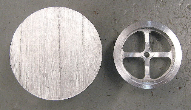
Think this is pretty neat to see the before and after shots of my flywheel (1.5" o.d. aluminum). This is for Liney Machines RV-1 engine that I'll be finishing in the next few weeks. All mill/rotary table and lathe work. I'll upload some pix of the machining if there is any interest :) Of course all this could have been done CNC in about 2 minutes (not counting the CAD/CAM/setup time), but where is the fun in that ?? :D This one took about 15-20 hours of my time being very careful to screw it up as little as possible. There's a couple of tiny spots where I dug in a little too far, but that's life ! Great experience to do this manually !

flywheelbeforeafter01.jpg


Here's THEIR completed engine picture from their website :

http://lineymachine.googlepages.com/

RV-1bigwhitebackground-large.jpg


Hope I can get mine that polished up !! BLING BLING !

Edit : fixed the picture viewing.
 
Nice work there Mike I bet that made you sweat!!, I find it terrifying doing long jobs like that on the RT,well done!, I made the RV2 and now I have the Halo kit,still trying to get my head round the plans ???.....Giles
 
I wonder if that is polished or plated. Looks great!

You flywheel looks great too.

E
 
Nice work Mike. Great inspiration for me.

Cheers,
Phil
 
Quick clarification :D

The picture of the completed engine is from Liney Machines website, not mine, unfortunately :p

I WISH & HOPE mine will look that good ;D

I wonder if that is polished or plated

I think that it's polished and painted. Brass/AL can look pretty good when all purt'ied up !

Nice work there Mike I bet that made you sweat!!, I find it terrifying doing long jobs like that on the RT,well done!

That was longest experience with the rotary table. Geeeeeeezzzz, yeah, I was sweating a lot on that one. Moving thousandths at a time to line up the straight part of the spokes with the curved ending of the arc. Always lifting the quill/end mill to test and make sure I was turning the mill table X/Y handles in the right direction. Heavily relied on the mill DRO. Excellent learning experience.

I made the RV2 and now I have the Halo kit,still trying to get my head round the plans Huh.....Giles

The RV-2 looks really cool too ! Post some pictures ! I like the flat-4 look to it. Definitely a unique looking engine :)

Here's the Halo video from YouTube. The engine sounds like a V-8 when he rev's it. Very throaty roar - very cool !

[youtube=425,350]G3E2tv8UgfU[/youtube]

Mike
 
Hi , if you go to the customers engines gallery on their site ,mine is "mr. Simmons" in Italy, the "unknown machinist" pics are also mine, I did tell him that they were mine but he hasn't got round to updating the page yet!, as for polishing,I use a blue polish stick, normally used for silver, on a 4" felt wheel in the taig at about 2000rpm, even the ali comes up nearly as good as theirs!.......Giles
 
ChooChooMike said:
... All mill/rotary table and lathe work. I'll upload some pix of the machining if there is any interest :) ...

Count 1 for interest in the machining pics

Eric
 
Nice job there Giles !!

You should post those pix on here too !

as for polishing,I use a blue polish stick, normally used for silver, on a 4" felt wheel in the taig at about 2000rpm, even the ali comes up nearly as good as theirs!.......Giles

Thanks for the tips. I haven't gotten around yet to polishing. Didn't think about chucking some kind of polishing wheel into my Sherline .... although my I'm thinking shop class at school (where I've been making the parts) has a good polishing wheel and necessary goodies

I'm hoping to finish the machine work in the next couple of days, clean up the parts and see if the engine will run ! Then I'll thinking about bling'ing it all up :)

Eric said:
Count 1 for interest in the machining pics

OK, I've got plenty when I was machining the flywheel and most of the other parts. Think I'll post a separate thread on the whole engine machining.

My shop instructor was asking why I'm taking all the pix ? Told him cause I'm documenting my progress and to pass it along to others who are interested and can learn and help me learn in the process. Pay it forward .... :) There's not enough info out there for newbie machinists like myself, so if I can increase that info flow, all the better !

Mike
 
Nice work Mike. A few more like that under your belt and you'll be a pro in no time. 8) Can't see were you dug in. Would lile to see more pics, too.

Bernd
 
Time for a bit of unabashed advertising - although 'advertising' free software seems a bit oxymoronic.

If you want to build flywheels like Mike's, with any number of straight or tapered spokes, my FLYWHEEL program will simplify your work considerably.

I'm going to attach a sample output from that program to this post. Not sure how that will work but we'll give it a try.

View attachment FLYWHEEL.OUT
 
Bernd said:
Nice work Mike. A few more like that under your belt and you'll be a pro in no time. 8) Can't see were you dug in. Would lile to see more pics, too.

Bernd

Hehehehe, the 1 small gouge in the flywheel in on the other side - guess I got lucky when taking the picture and had the nice side up :p

I'll start post some of the build pix here over the weekend.

Marv said:
If you want to build flywheels like Mike's, with any number of straight or tapered spokes, my FLYWHEEL program will simplify your work considerably.

Marv mentioned that one to me last month at our home shop club meeting here in SoCal

www.schsm.org

I did check it out and may use Marv's program in the future. Given (what was supposed to be) the easy math for 4 identical spokes, once you have the coordinates figured for 1 quadrant, they're the same for the other 3 :).

One REALLY BONEHEAD mistake I made was when I setup my rotary table in the mill to drill the initial holes in the spokes corner areas, I didn't set the rotary table index to 0 degrees. It was randomly set to something like 217.6 deg.

DUHHHHHHHHHHHHHHHHH !

All my subsequent arc's where then a bit of a pain since they didn't start off at 0, 90, 180, 270

Let's see, 217.6 + 90; + 180; + 270 .....

Then offsetting 23.7 deg for the arc start, then swinging a 53.7 deg arc, ;D ::) repeat 3X with different #'s. At least it wasn't a catastrophic error, just required calculating the degree offset ahead of time for all 4 quadrants and then really paying attention to the rotary table dial. Yeah, my brain was a bit fried after all that :D

Mike
 
Using a program (your own, mine or someone's) not only does the math for you but, if properly written, produces a work sheet with all the operations laid out for you to carry to the shop - see the example I posted above.

I find that the automated planning function of the program is more important than the fact that it did the calculations for me. I can do the calculations on the run but find, as you seem to have found, that it's easy to let something important slip by if one doesn't have a written procedure to follow.

Of course, not everyone works this way. If you've made a dozen or so flywheels already, chances are you may not need such a finicky procedure to follow. However, for newcomers who have never made a spoked flywheel, having a plan to follow is a good idea.

If you're making tapered spokes, the RT angular offset needed to bring the spoke side parallel to the x-axis for machining will, in general, be an oddball number, e.g. 3.133 deg in the example output.

Since flywheel dimensions are almost never super-critical, the program computes the solution closest to your input parameters that makes this angle a nice integral number. This makes cranking in the turns from spoke to spoke much easier and much less prone to error.

 
Since we're showing flywheels. I'll show you mine. :D

Since I don't have a index table "YET" I had to line up the part to drill the holes the hard way. You can read how I did it on on my web site.

pic13.jpg


Marv:

What kind of program do you need to run that with? I was hesitant to down load it because it ended in "out".

Bernd

 
It's just a standard ASCII text file. Open it with Notepad or any text editor.
 

Latest posts

Back
Top