bananarchy
Member
- Joined
- May 14, 2013
- Messages
- 10
- Reaction score
- 14
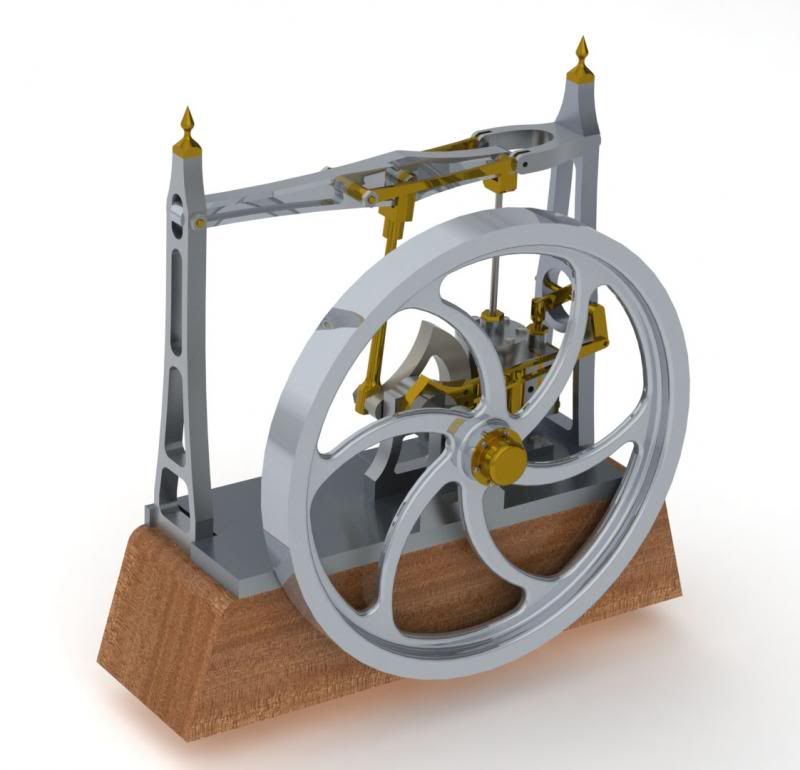
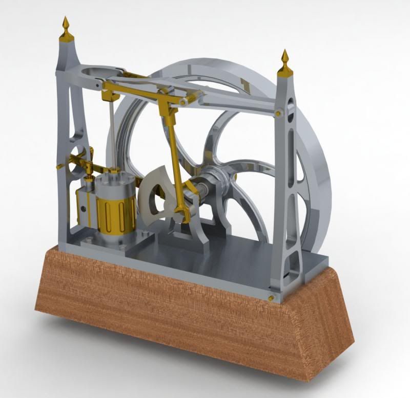
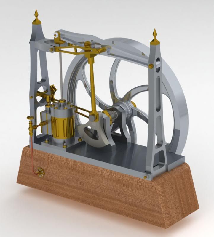
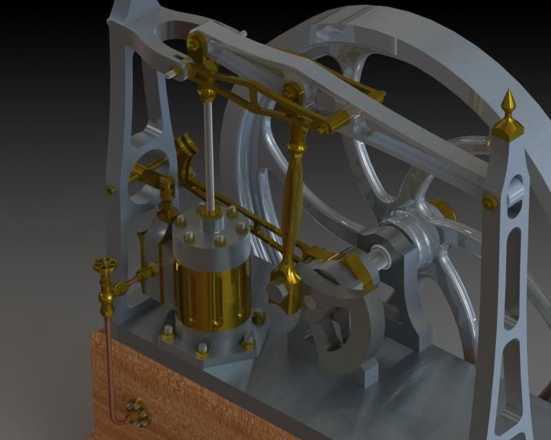
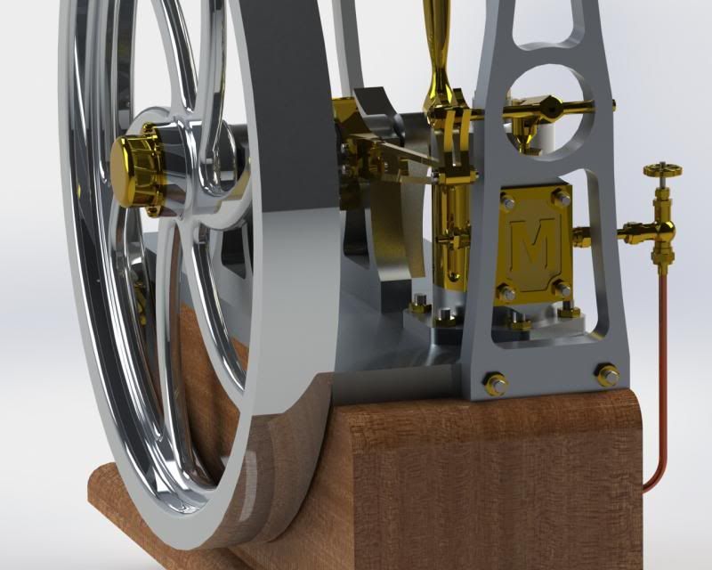
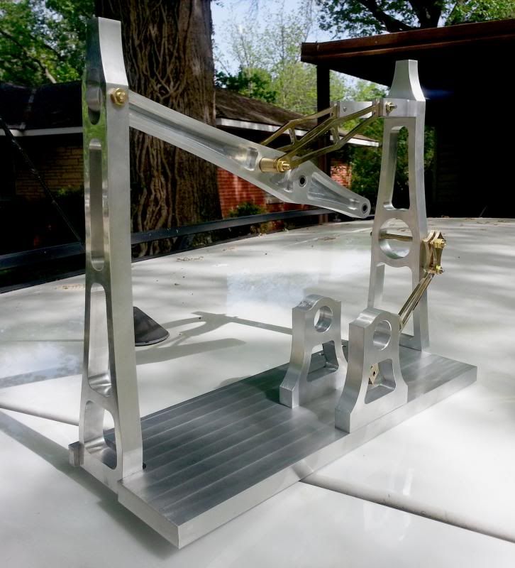
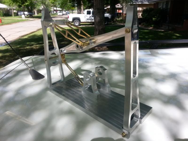
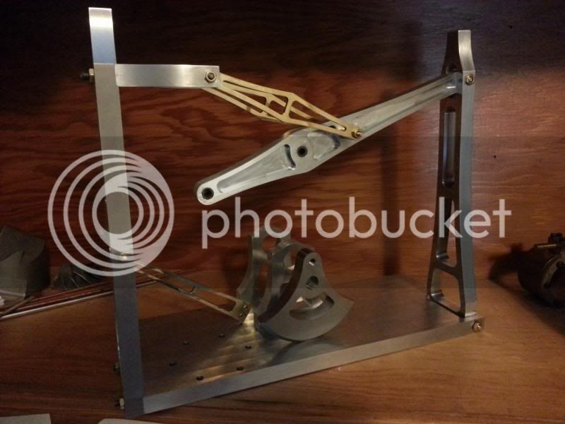
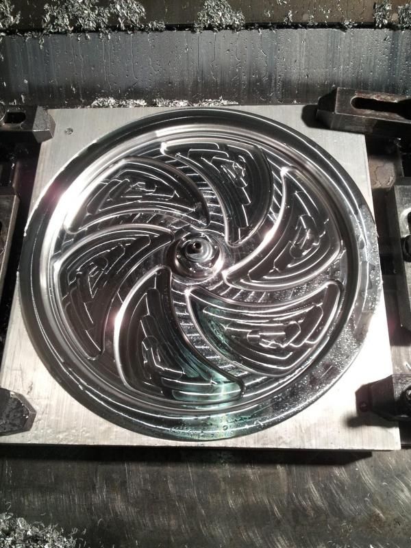
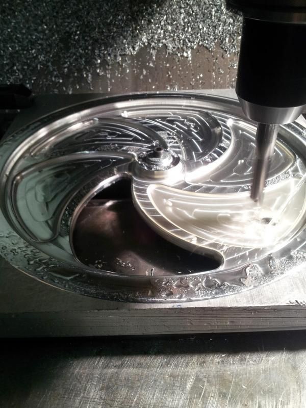
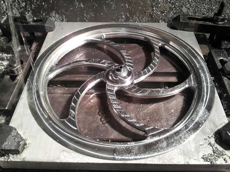
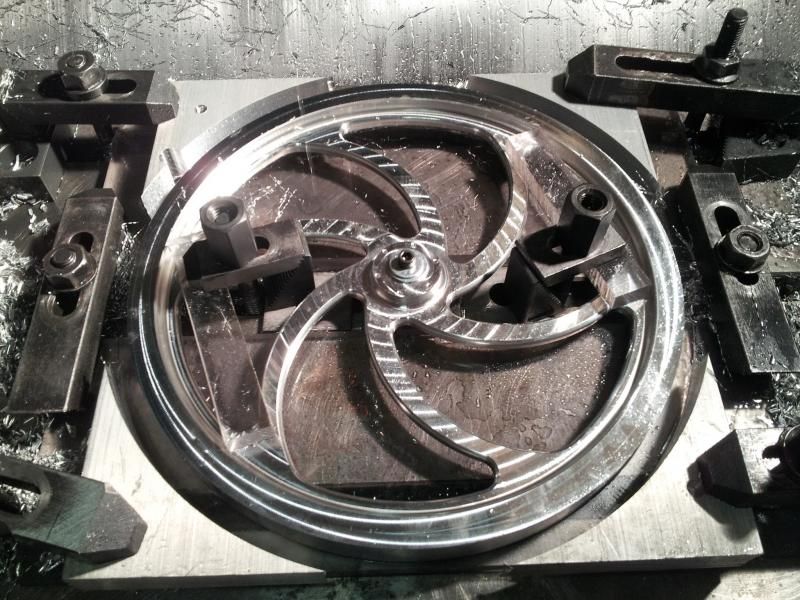
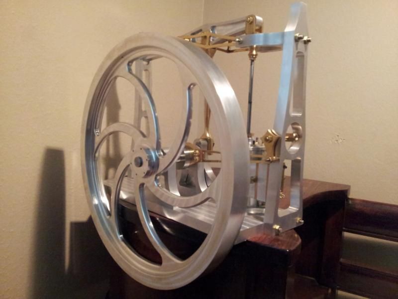
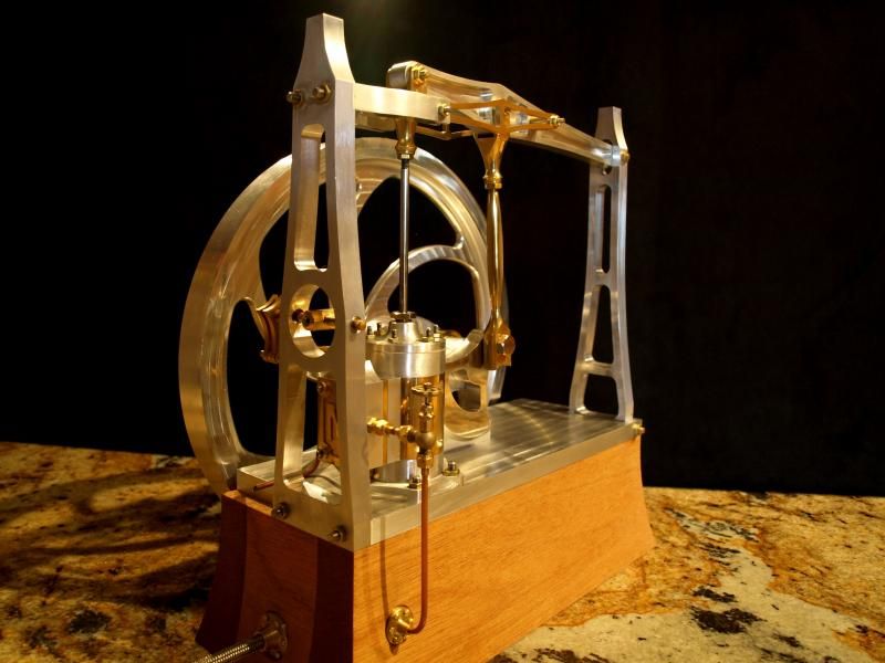
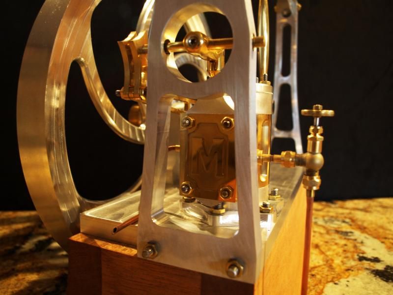
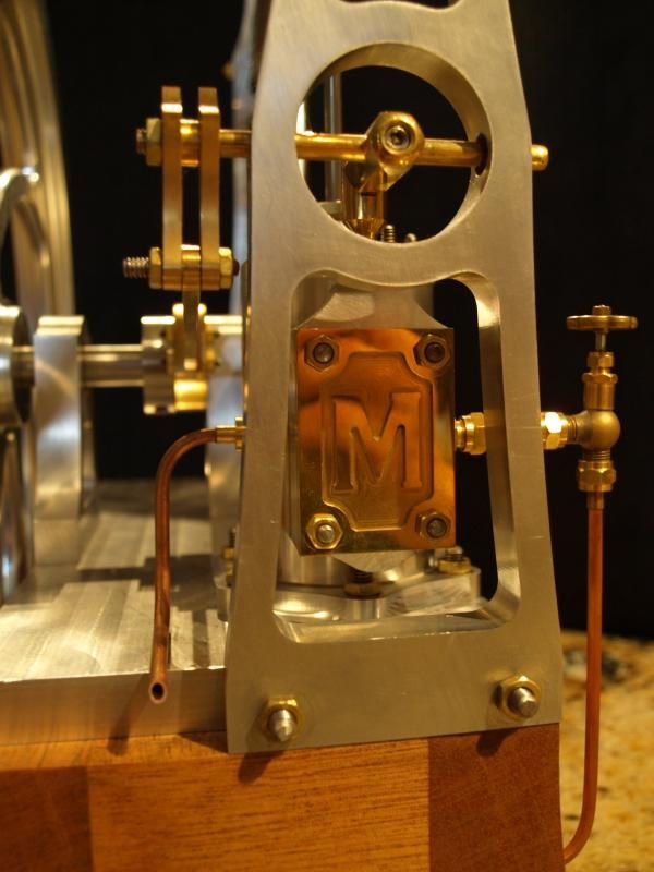
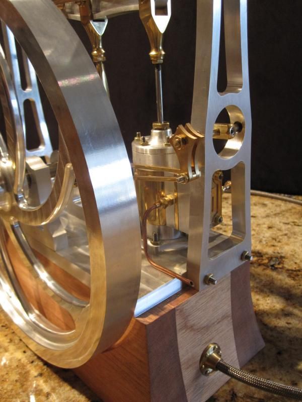
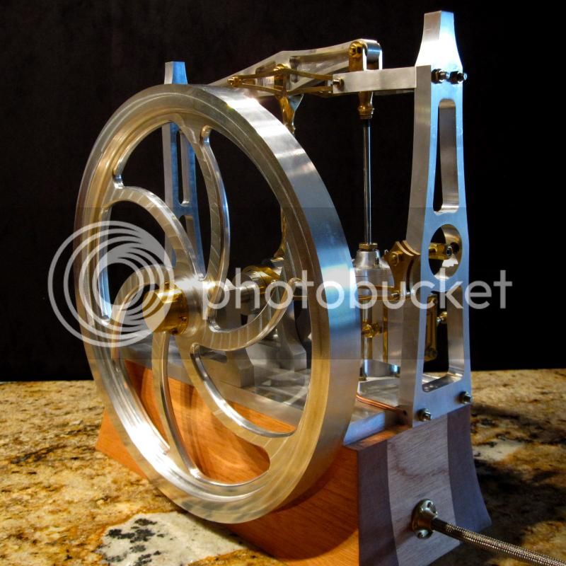
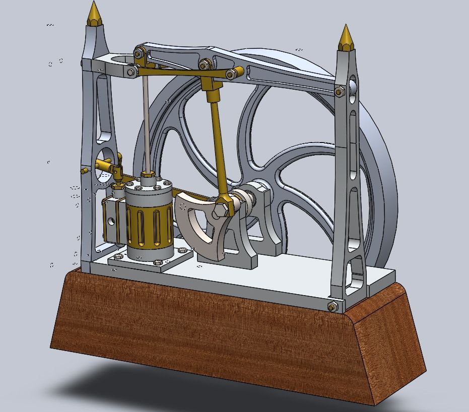
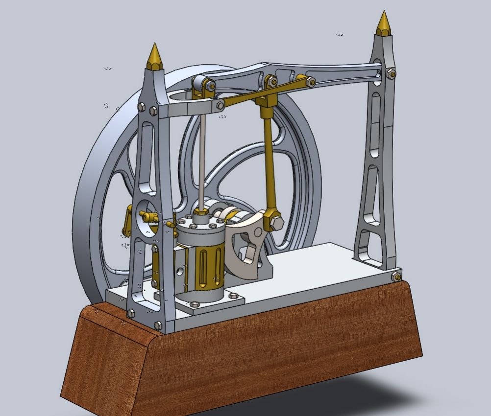
Howdy folks. Now that I've spent a good deal of time on these boards admiring everone else's handywork, it's finally time to start making some chips of my own. I've been doing various things in machine shops for a number of years, but this is my first foray into model engines. Elmer's #37 caught my eye, as I've always liked beam engines and grasshopper beams are particularly fascinating to watch. Never having been one to leave well enough alone, and having access to CNC capabilities, the original design has been substantially modified. The first iteration was simply a 2x scale up of the original design, followed by aesthetic modifications and a seriously overgrown flywheel (11.75" diameter). Here are a few shots of the solidworks model -
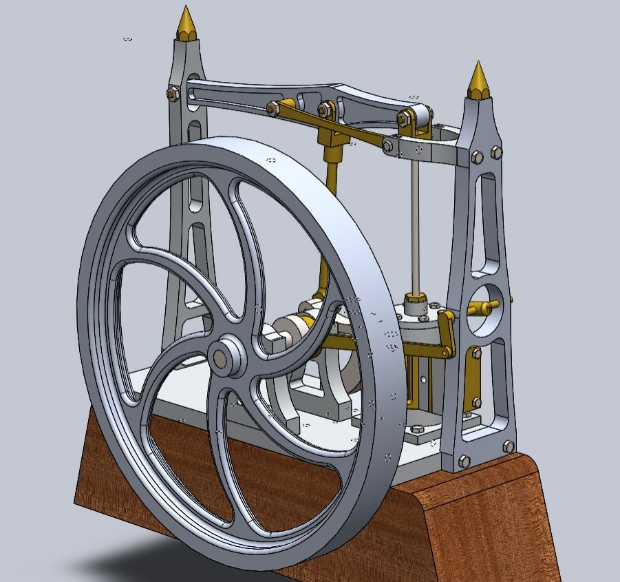
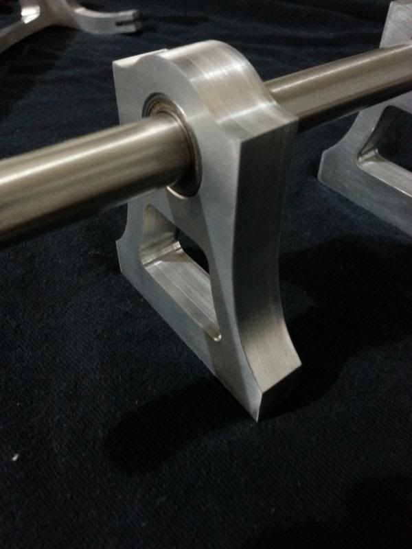
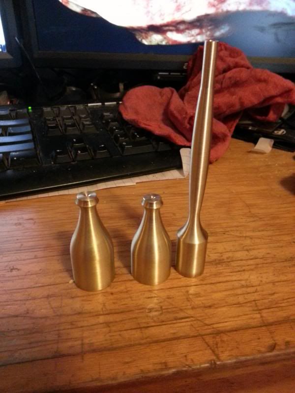
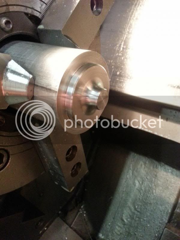
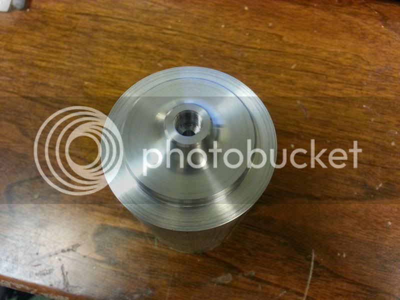
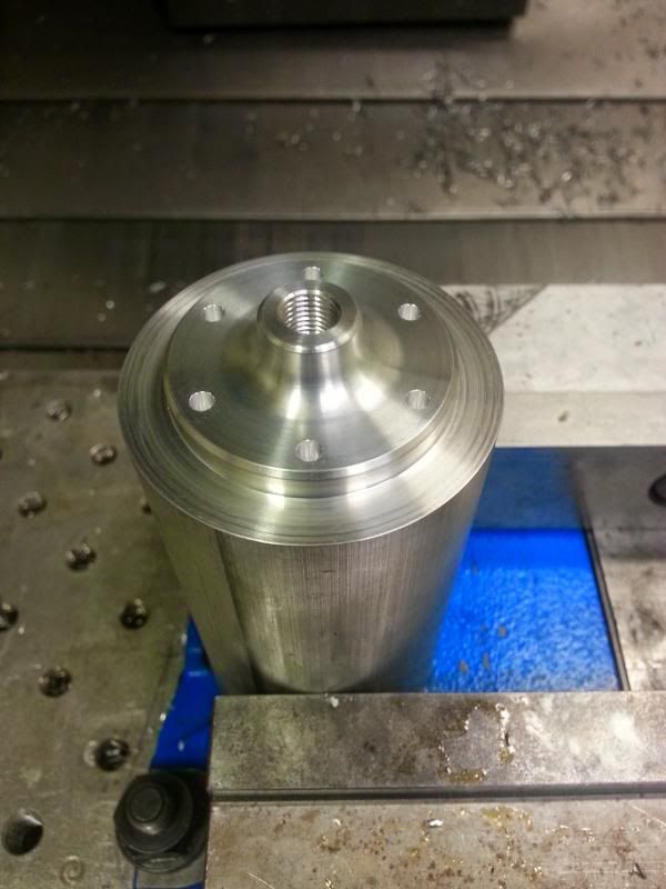
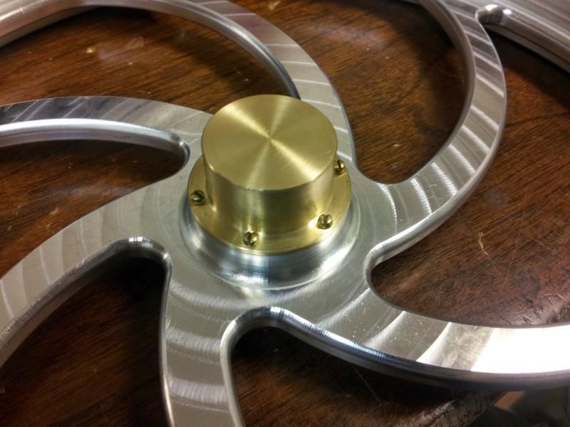
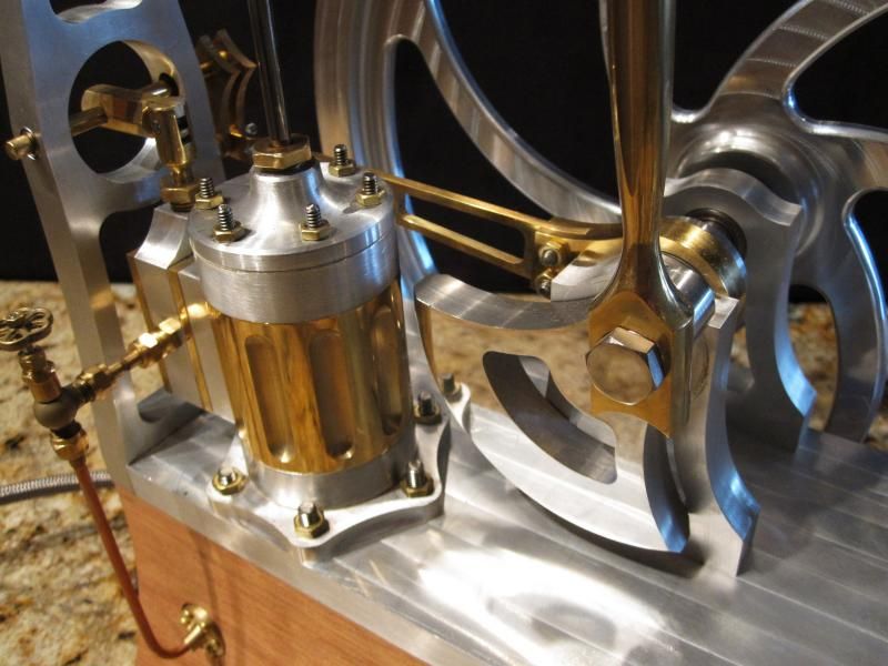
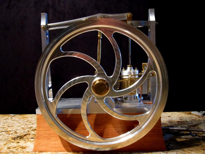
One of the main ideas behind the big flywheel, aside from looking neat, is to ensure smooth, very low speed operation. To that end, ball bearings are going to be used in all the rotating bits and nylon bushings for the pin joints to reduce friction. Also, using the weight and CG numbers from the model, the counterweight was significantly enlarged in order to offset the weight of the beam and give what should be reasonably good balance, again to ensure smooth running at low RPM.
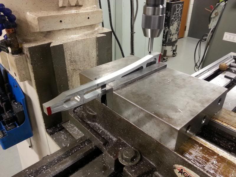
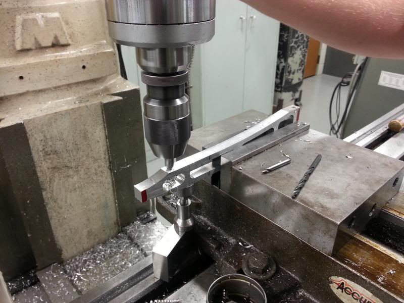
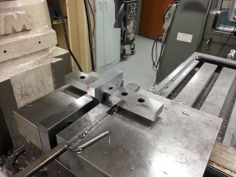
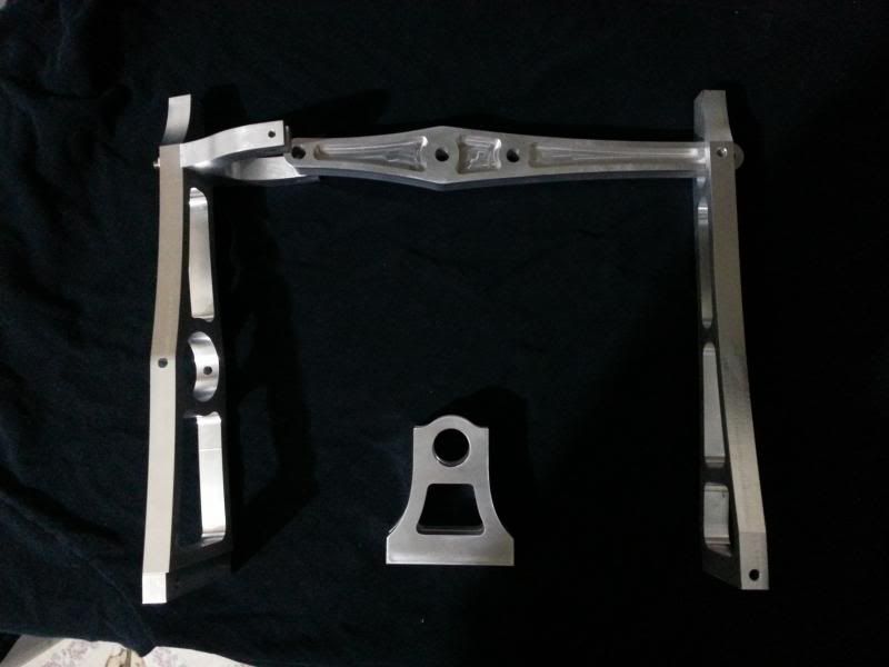
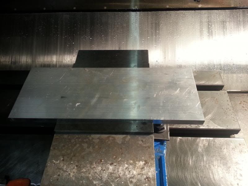
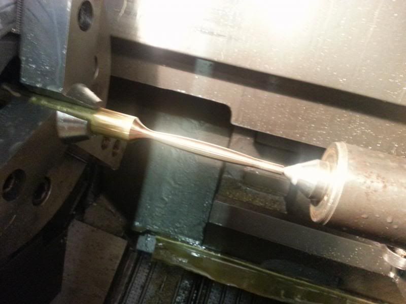
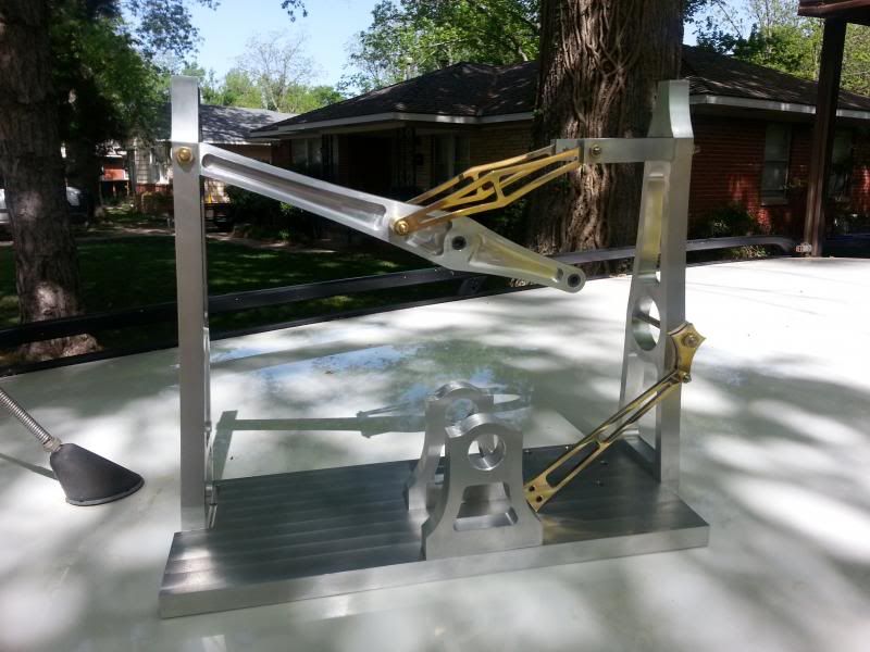
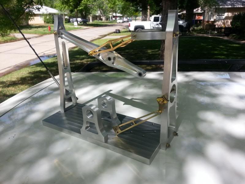
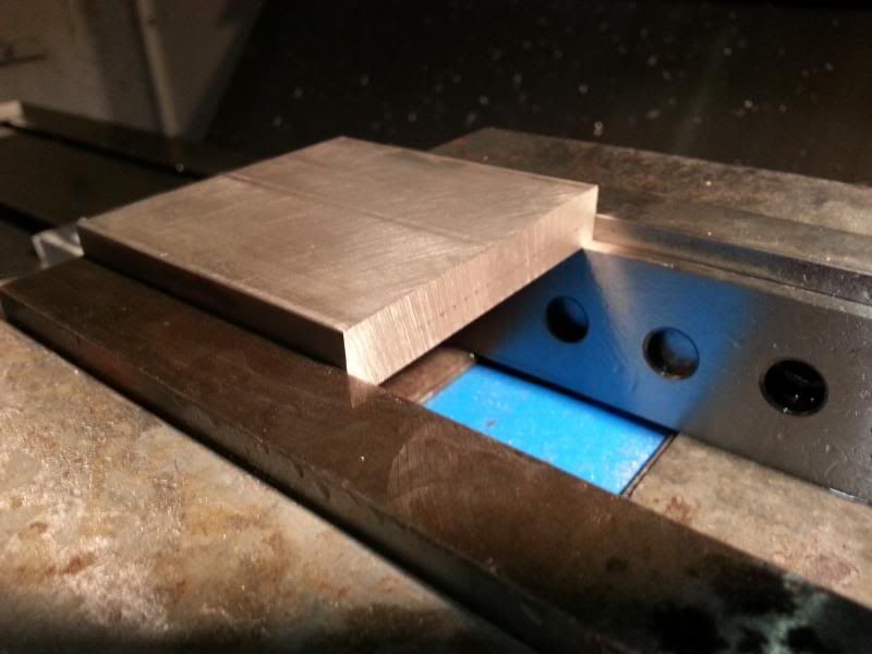
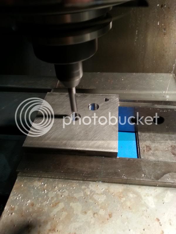
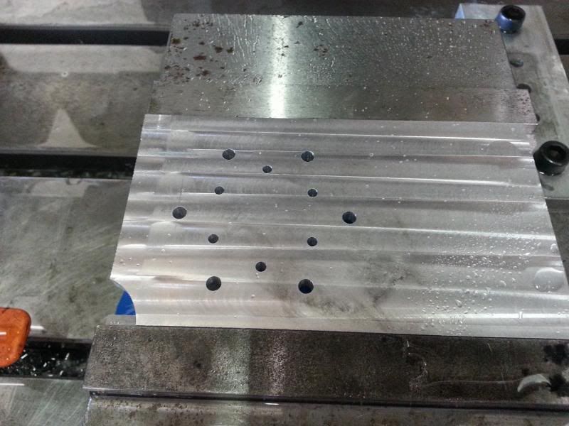
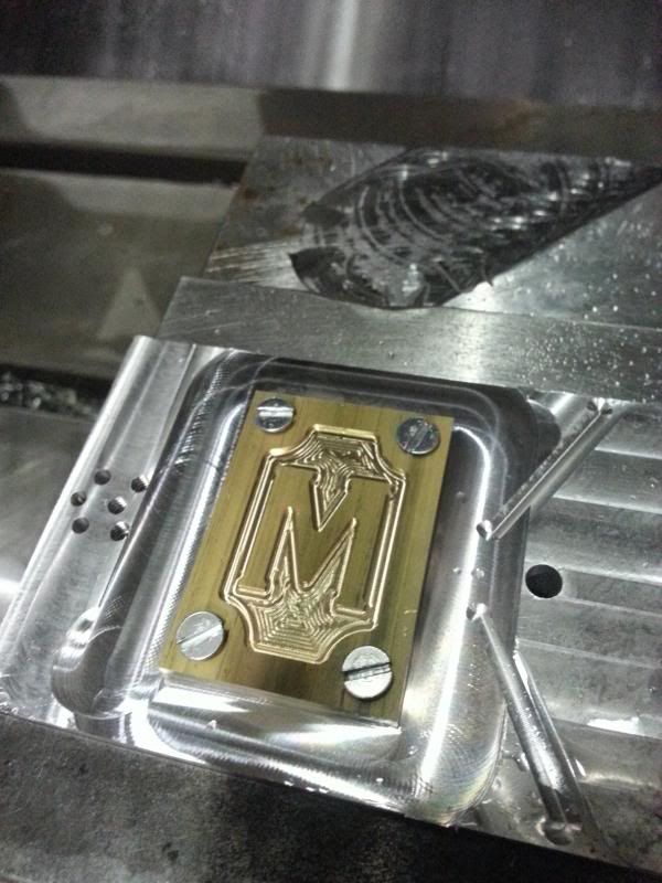
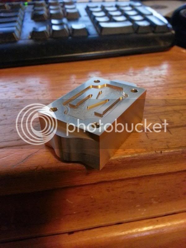
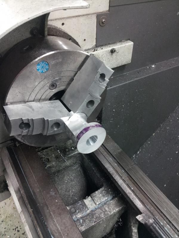
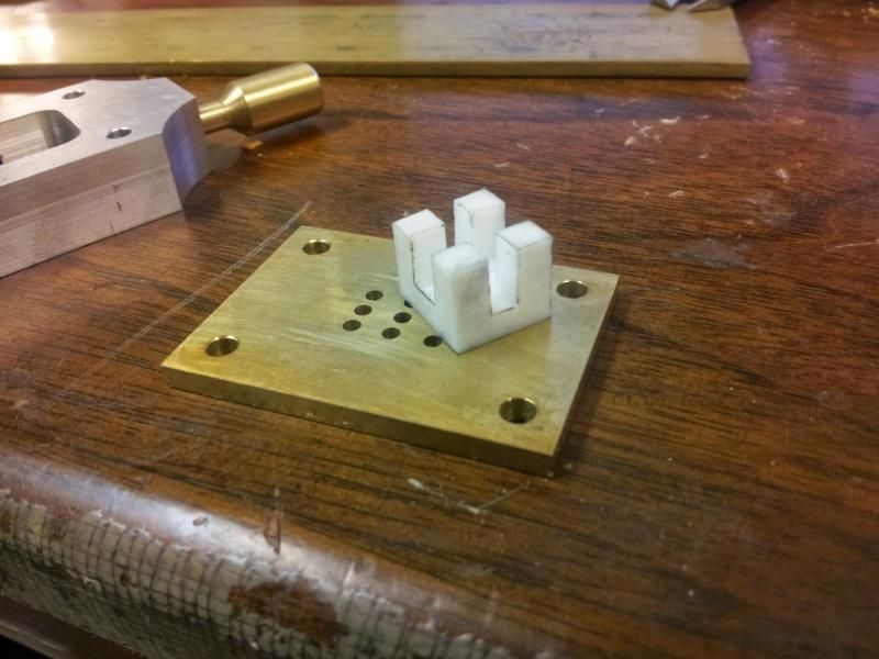
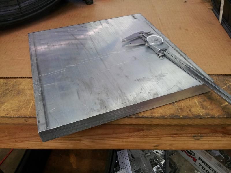
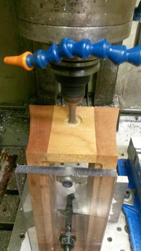
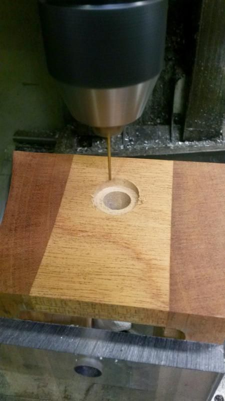
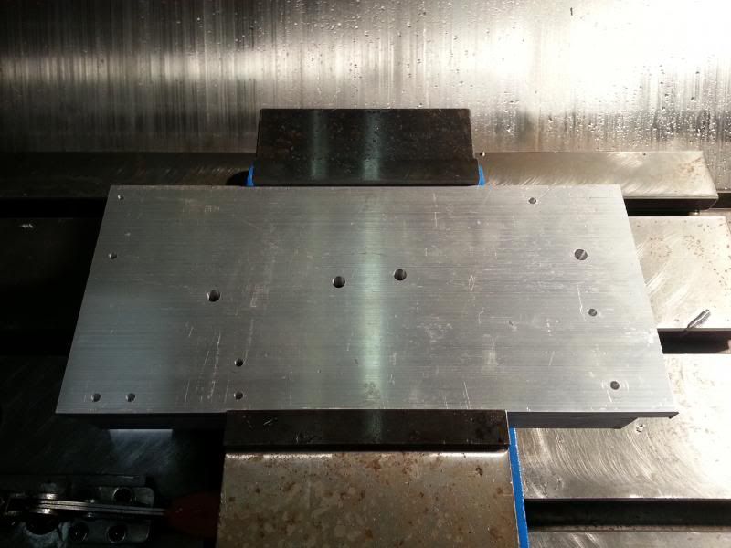
This last week, I finally got the chance to make the major CNC components all in one run, aside from the flywheel, for which I'm still waiting on material. First, fixture/bolt holes were drilled in a 6x13x0.5 plate for the column, leg, column fork, and beam.
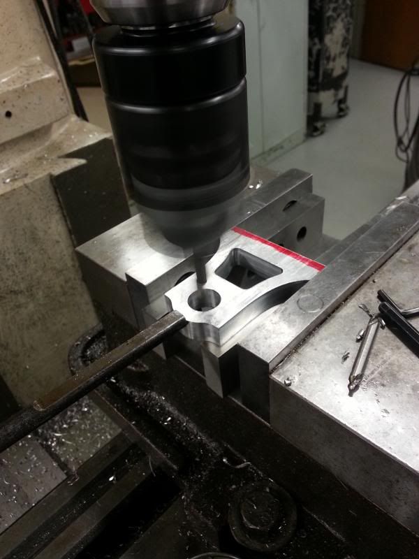
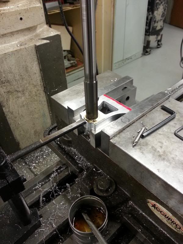
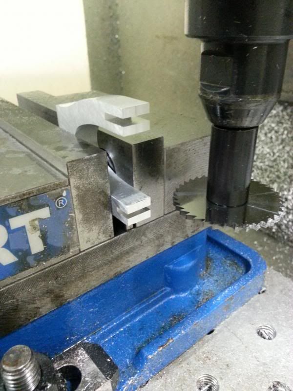
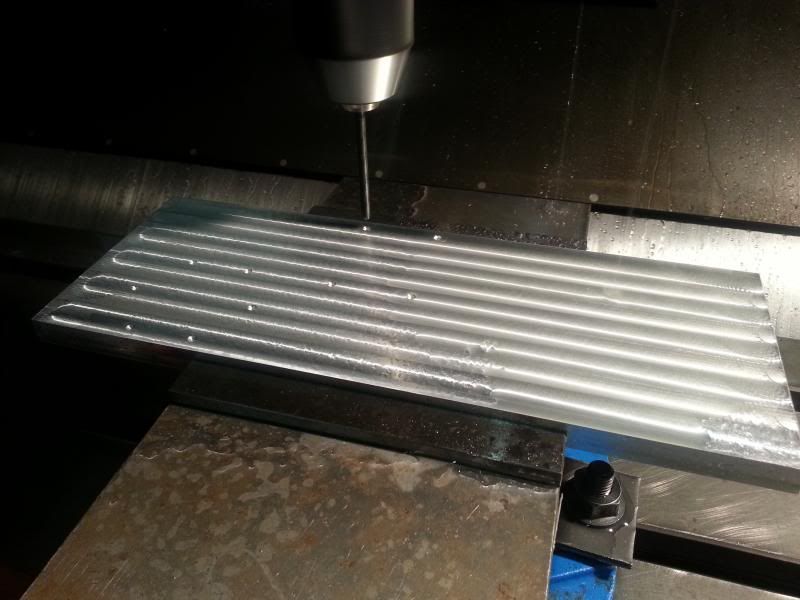
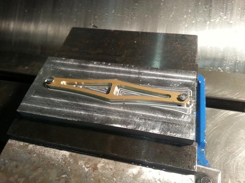
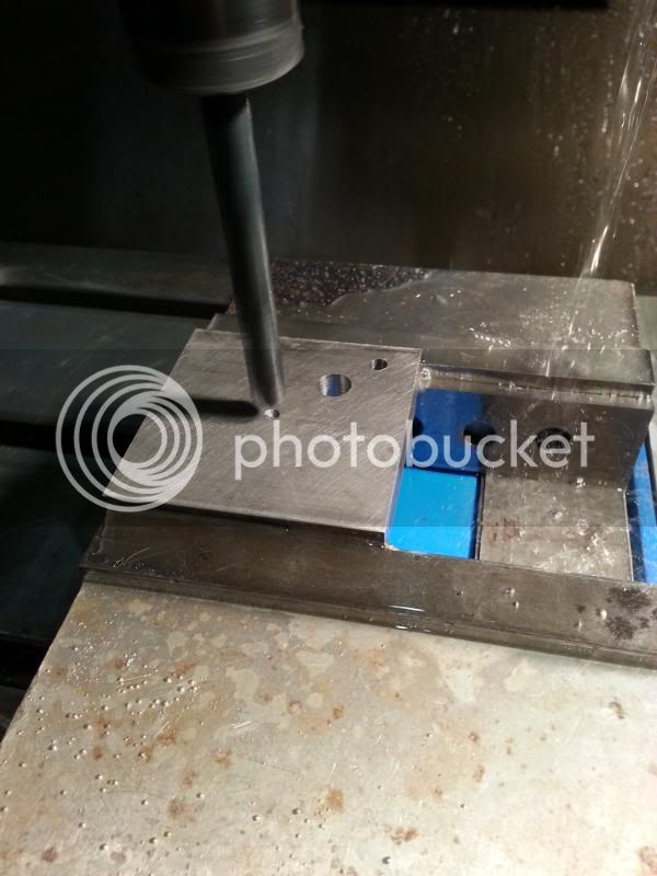
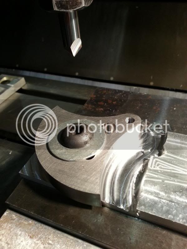
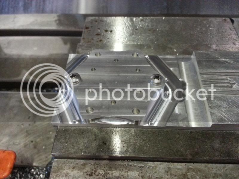
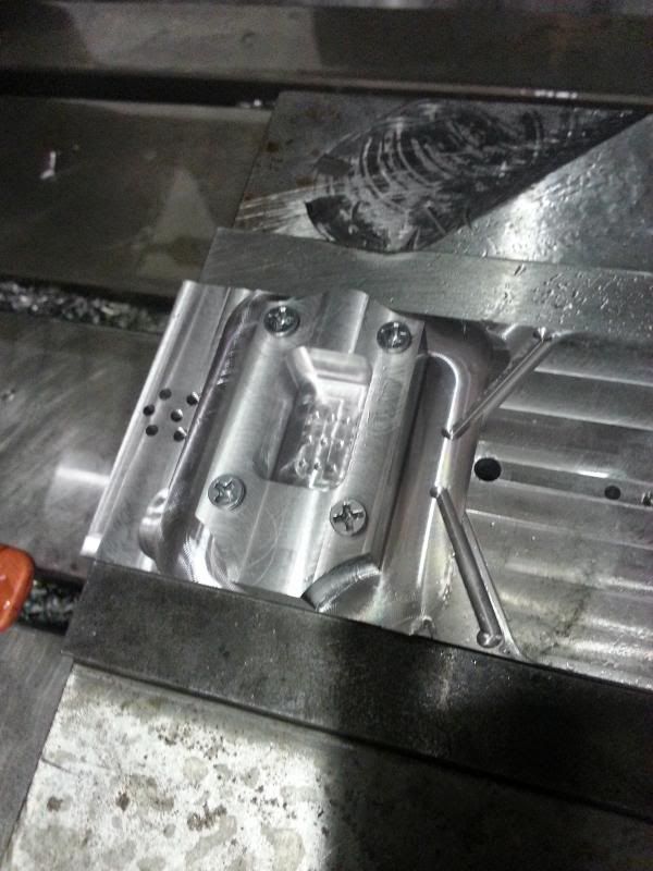
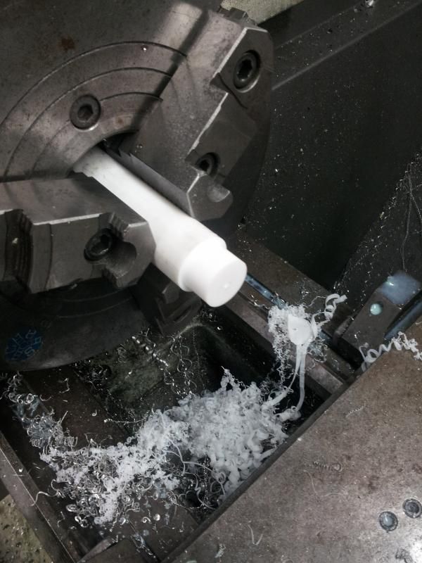
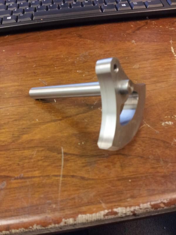
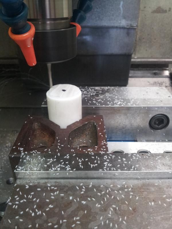
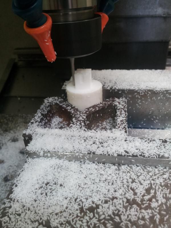
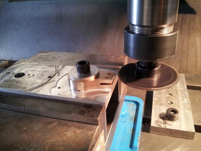
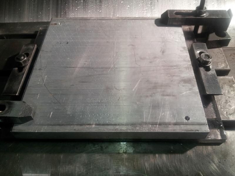
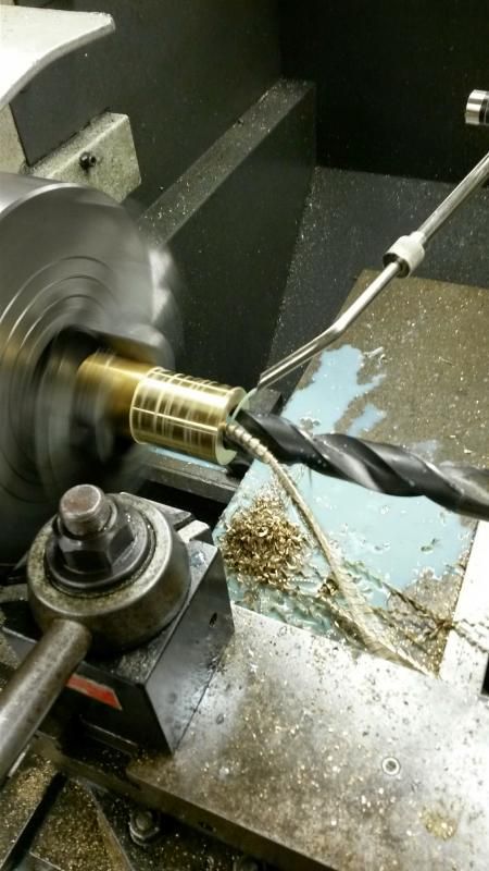
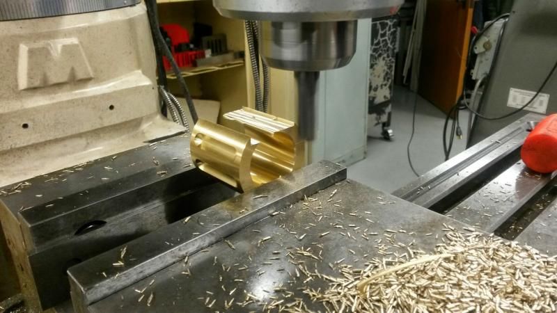
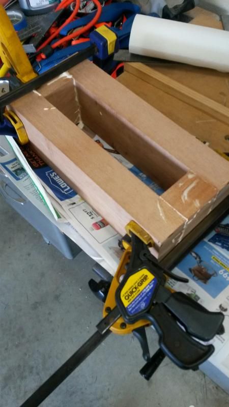
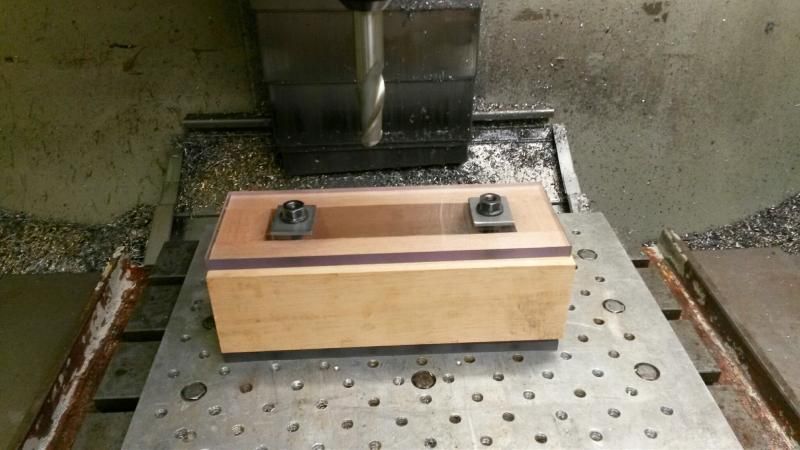
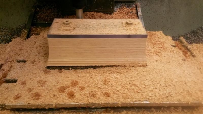
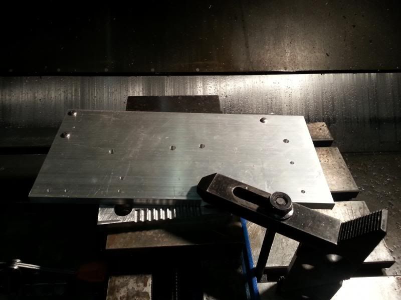
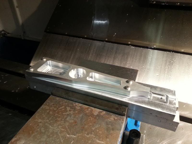
Next, a fixture plate was drilled, tapped, skimmed, and not photographed. The workpiece was bolted down, starting with the leg...
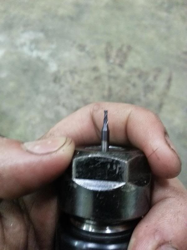
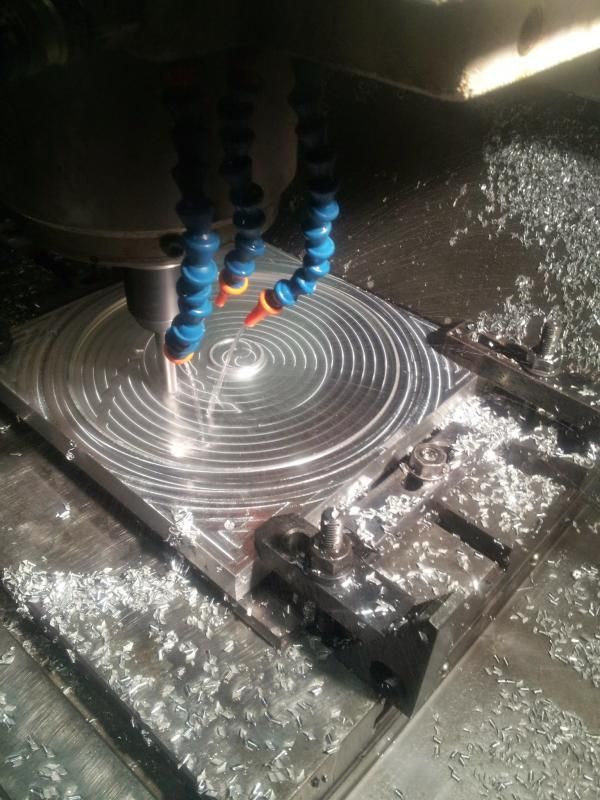
and cut at 7500rpm, 40ipm.
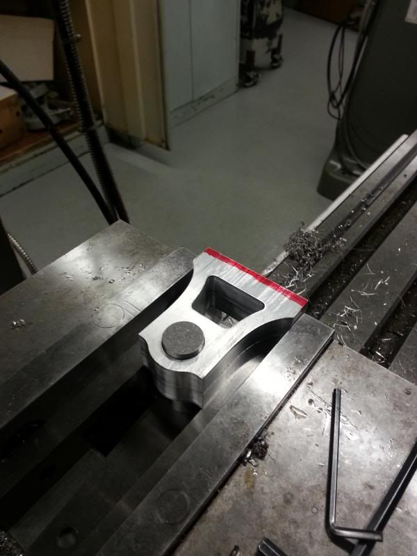
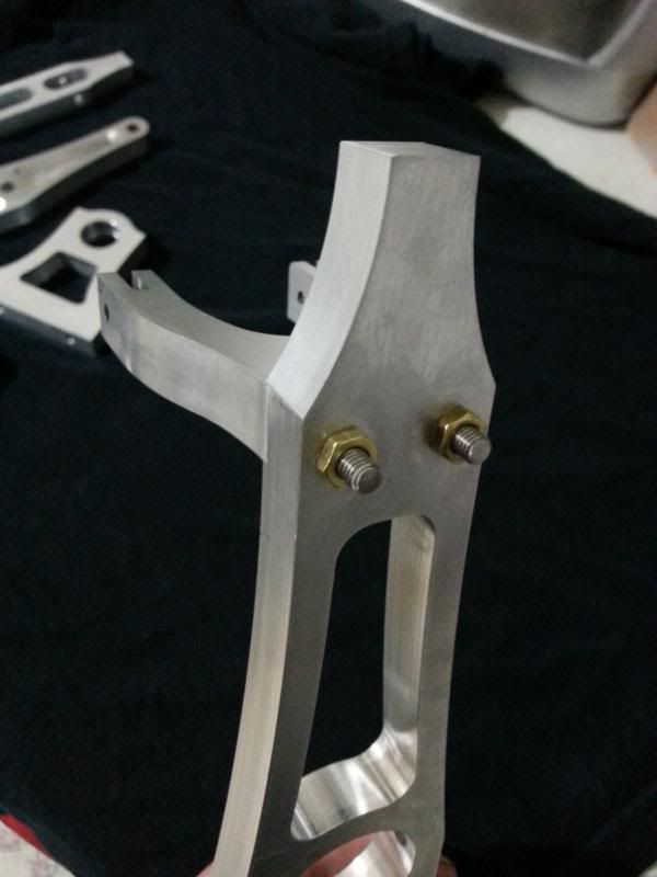
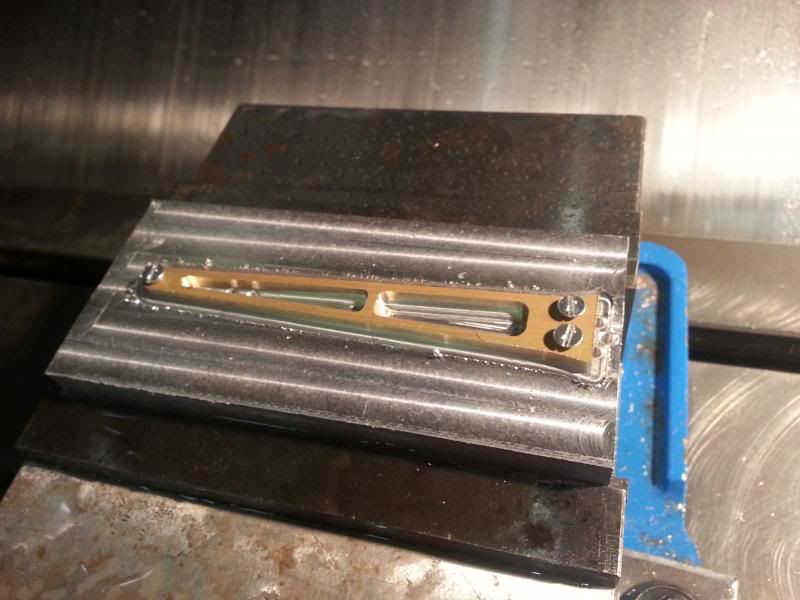
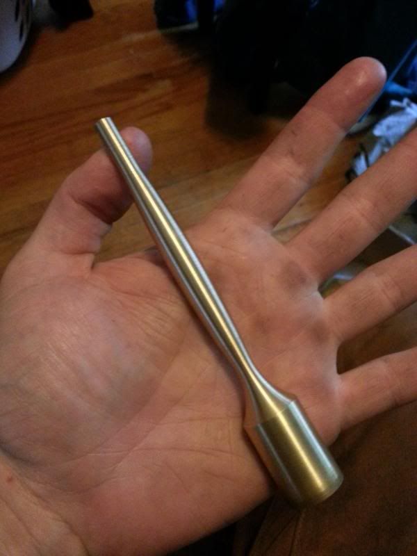
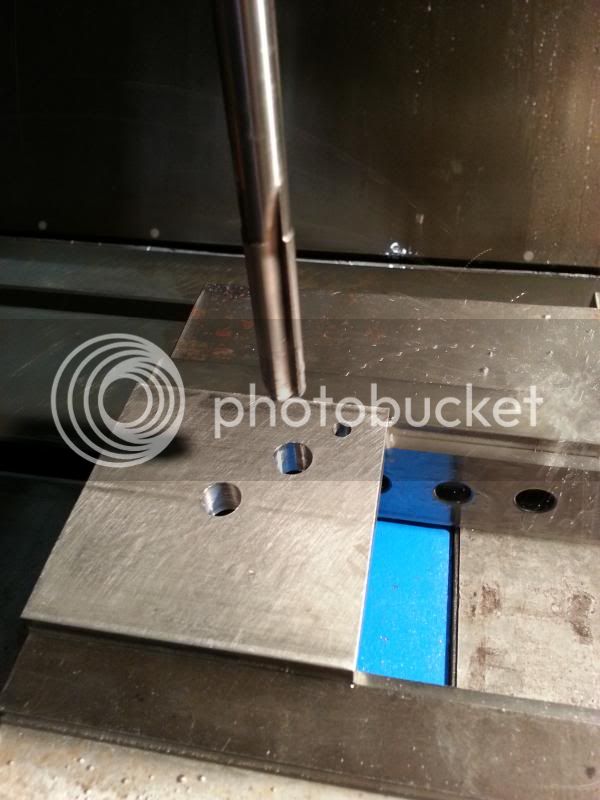
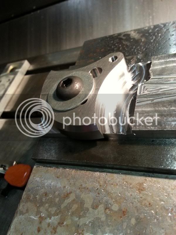
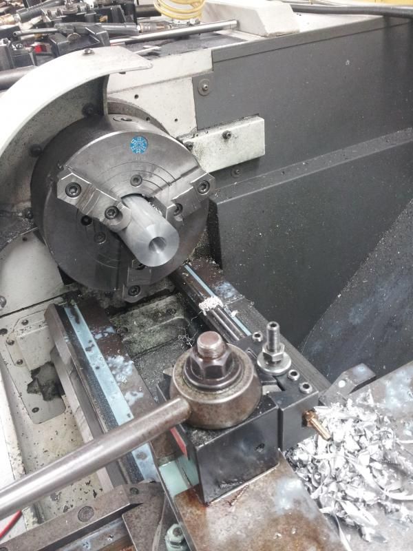
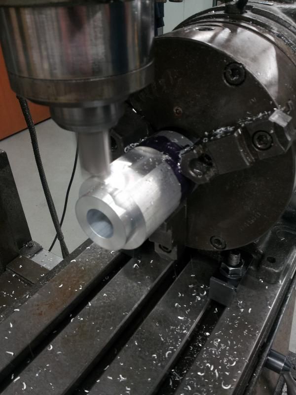
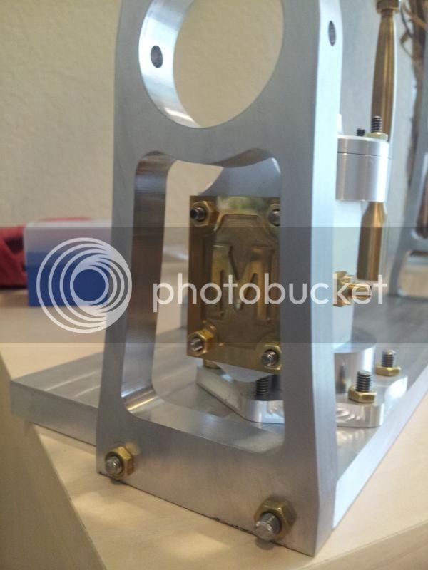
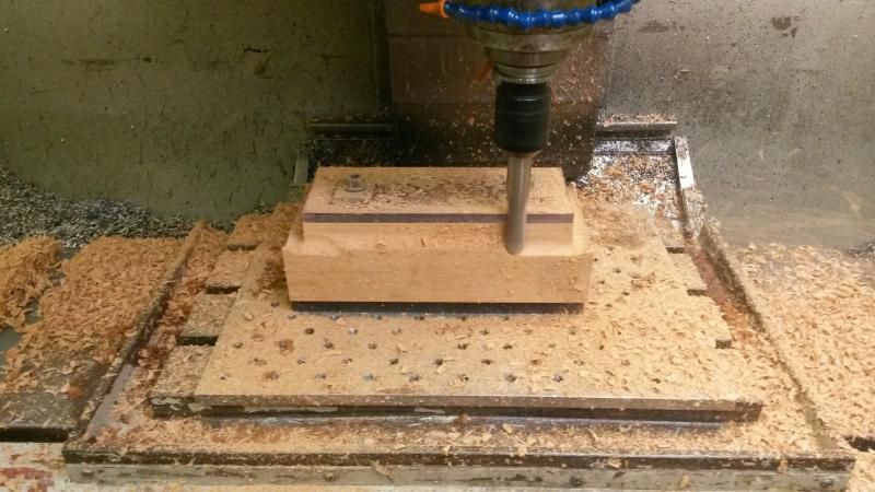
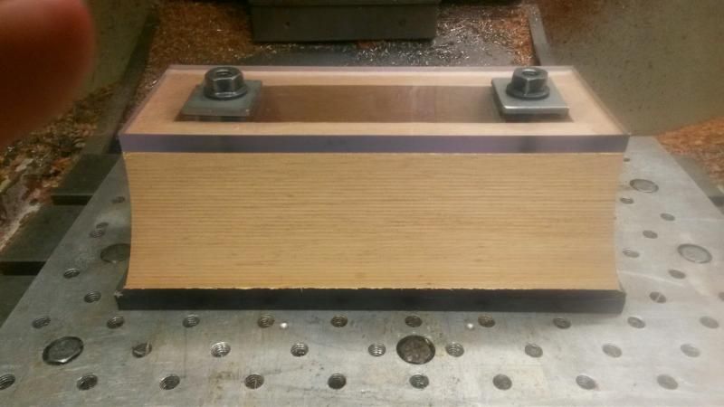
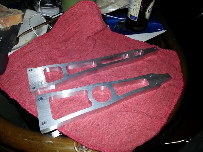
Then the column
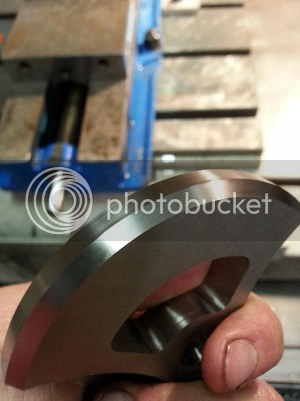
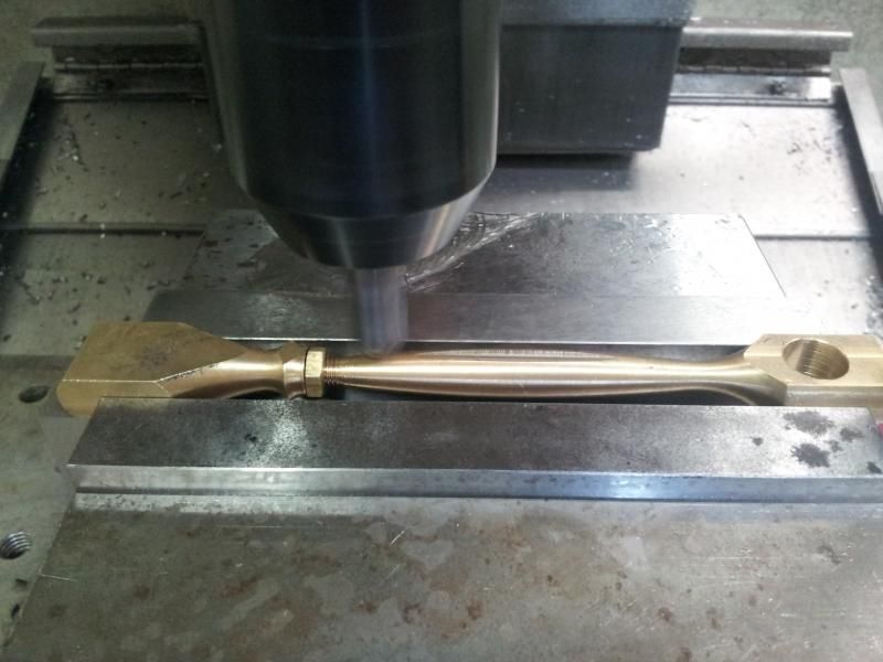
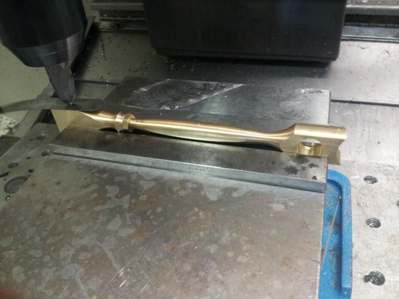
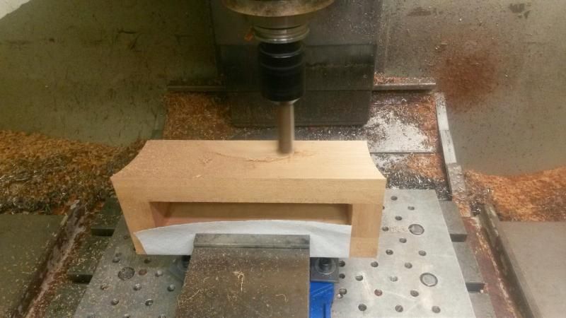
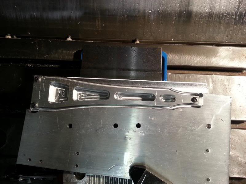
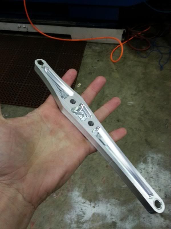
and the beam
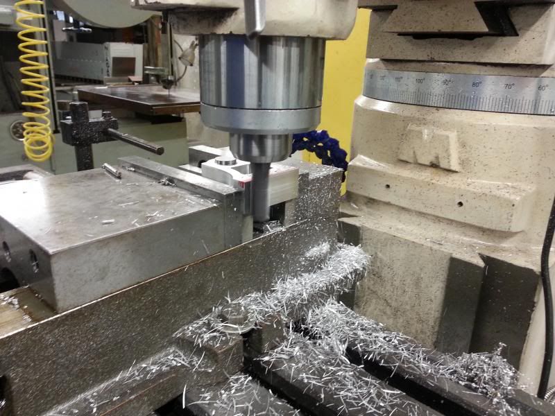
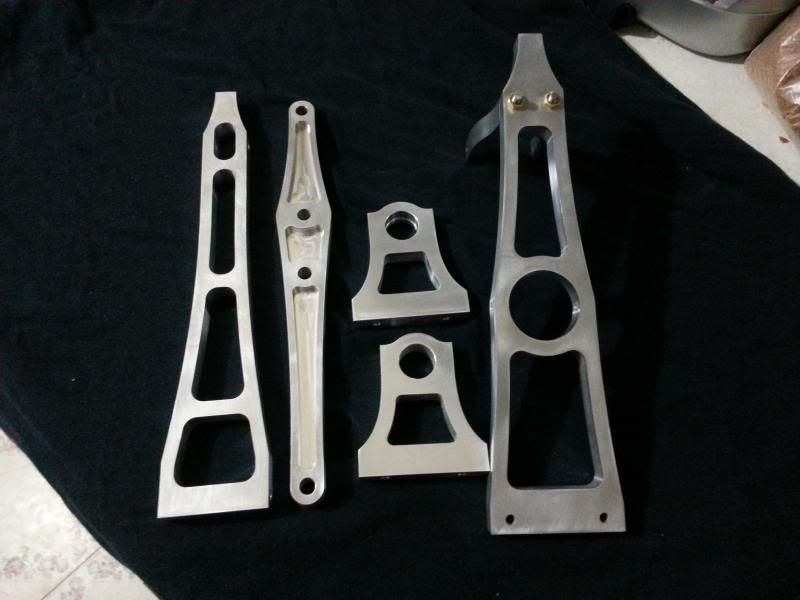
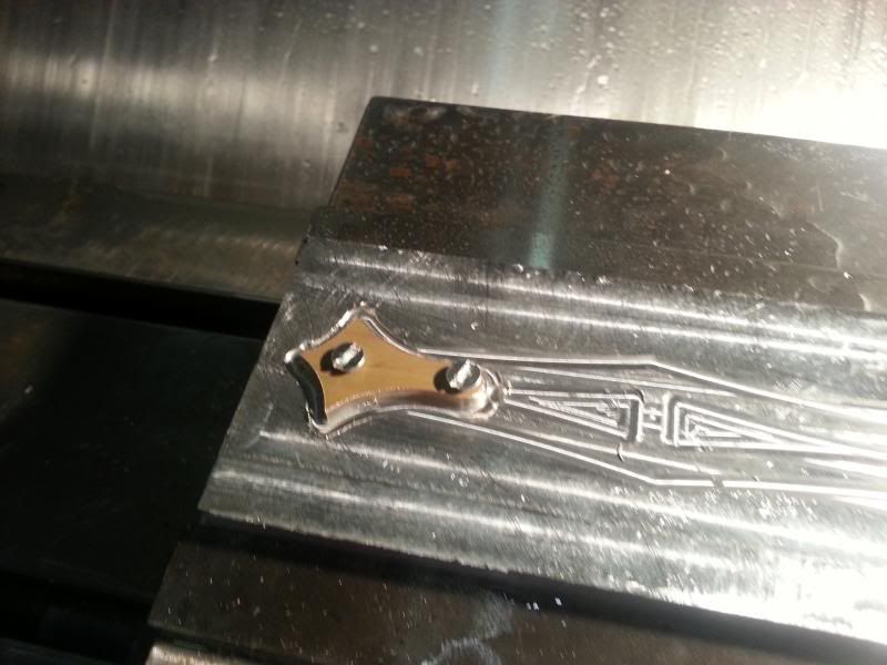
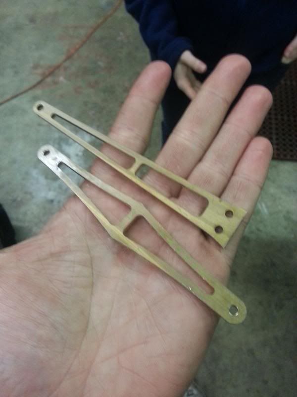
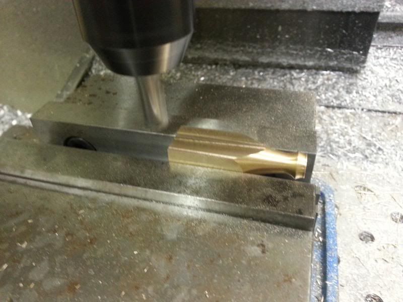
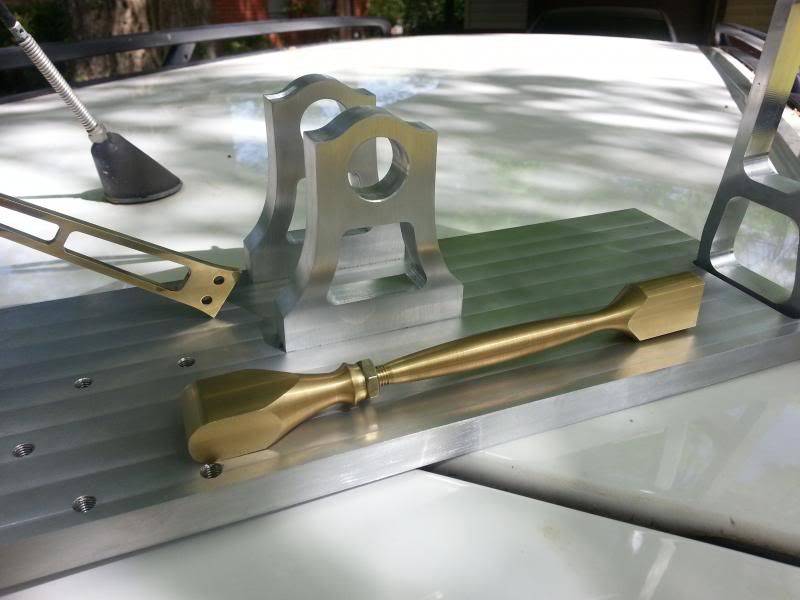
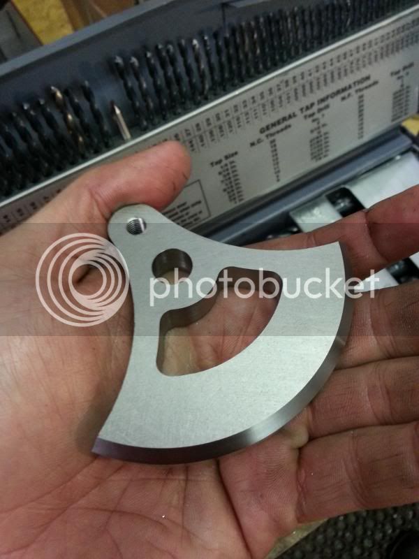
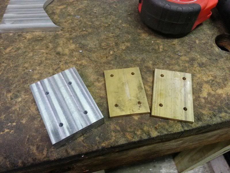
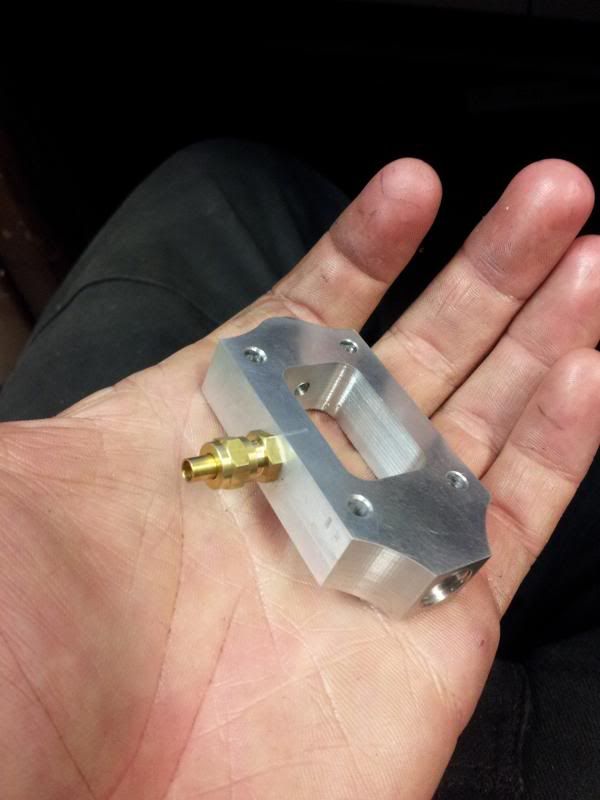
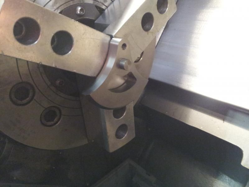
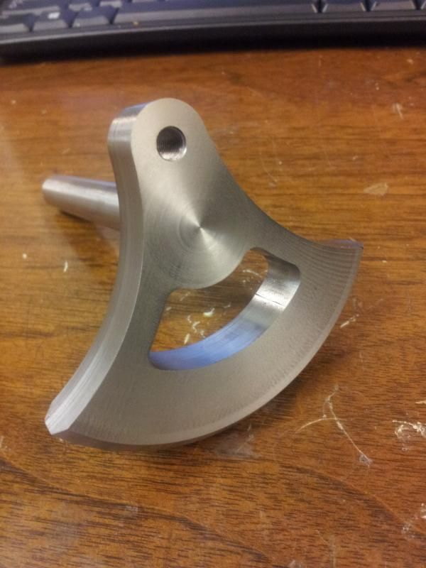
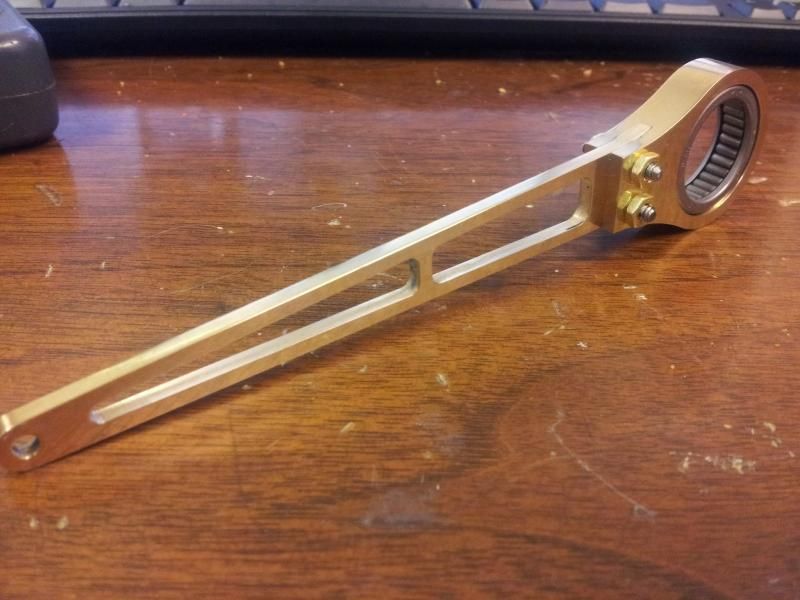
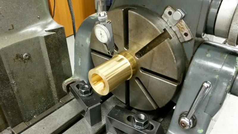
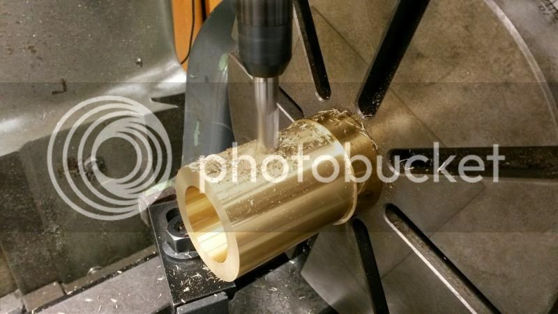
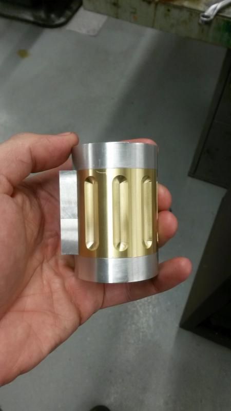
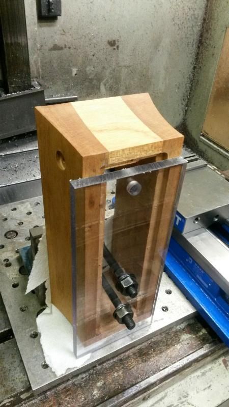
and the fork and bearings
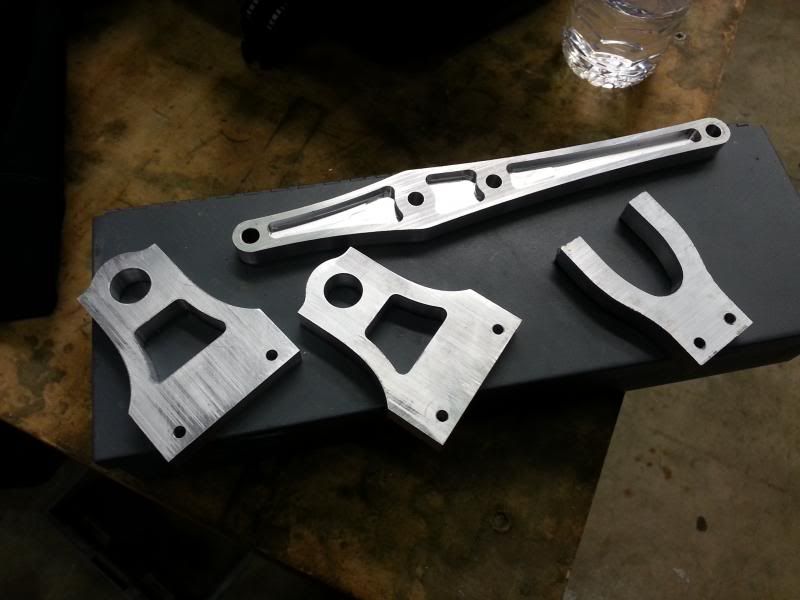
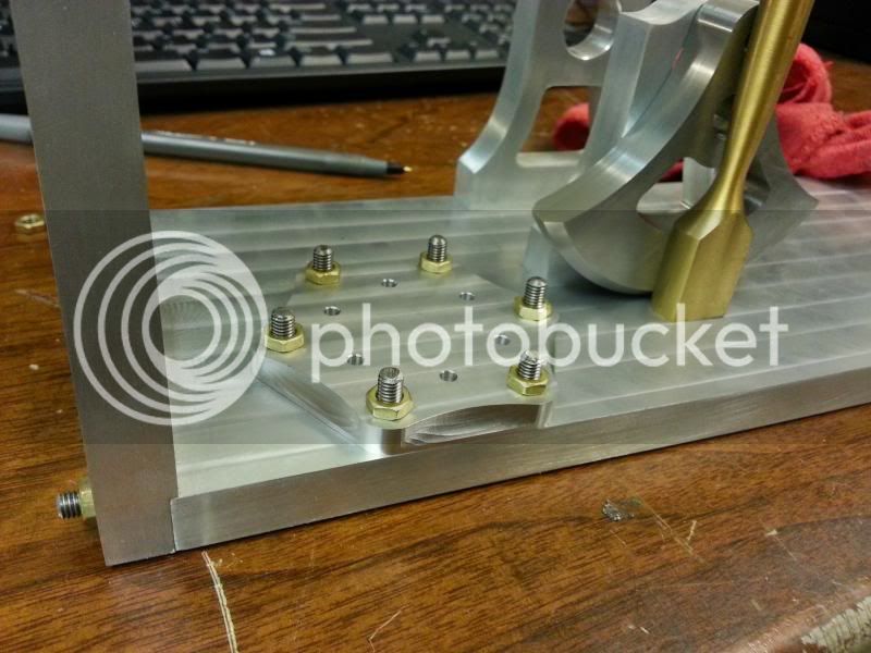
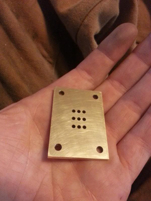
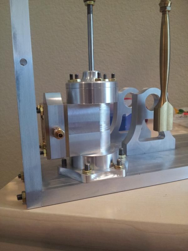
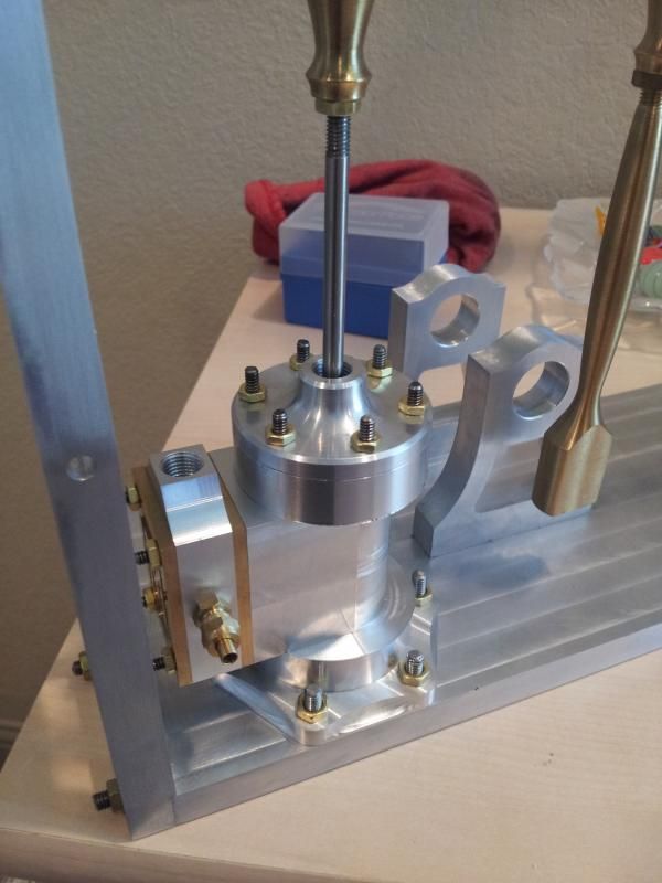
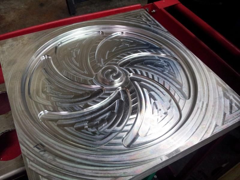
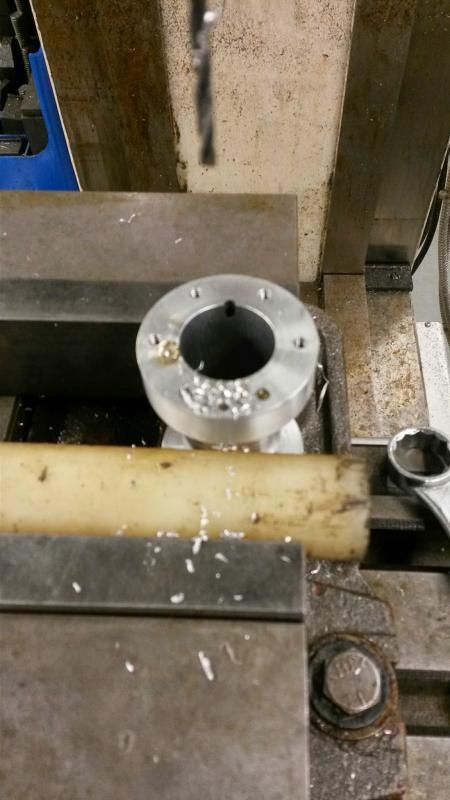
The fork, bearings and leg all have extra material and fixture holes which will be machined off in subsequent operations. The setup allowed all the parts to be machined using the same machine zero, which worked well. The only issue I encountered was the screws not quite being equal to the task of holding the fork down during machining, and it moved around a bit, but the damage is only cosmetic and it should be salvageable. Next up - cleaning up and doing remaining operations on the parts I have so far, then starting in on the base plate.
-Neil
One of the main ideas behind the big flywheel, aside from looking neat, is to ensure smooth, very low speed operation. To that end, ball bearings are going to be used in all the rotating bits and nylon bushings for the pin joints to reduce friction. Also, using the weight and CG numbers from the model, the counterweight was significantly enlarged in order to offset the weight of the beam and give what should be reasonably good balance, again to ensure smooth running at low RPM.
This last week, I finally got the chance to make the major CNC components all in one run, aside from the flywheel, for which I'm still waiting on material. First, fixture/bolt holes were drilled in a 6x13x0.5 plate for the column, leg, column fork, and beam.
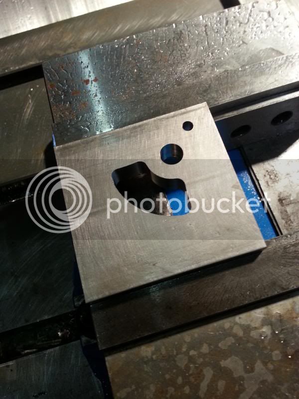
Next, a fixture plate was drilled, tapped, skimmed, and not photographed. The workpiece was bolted down, starting with the leg...
and cut at 7500rpm, 40ipm.
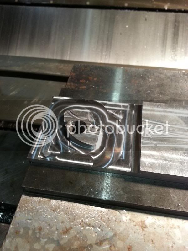
Then the column
and the beam
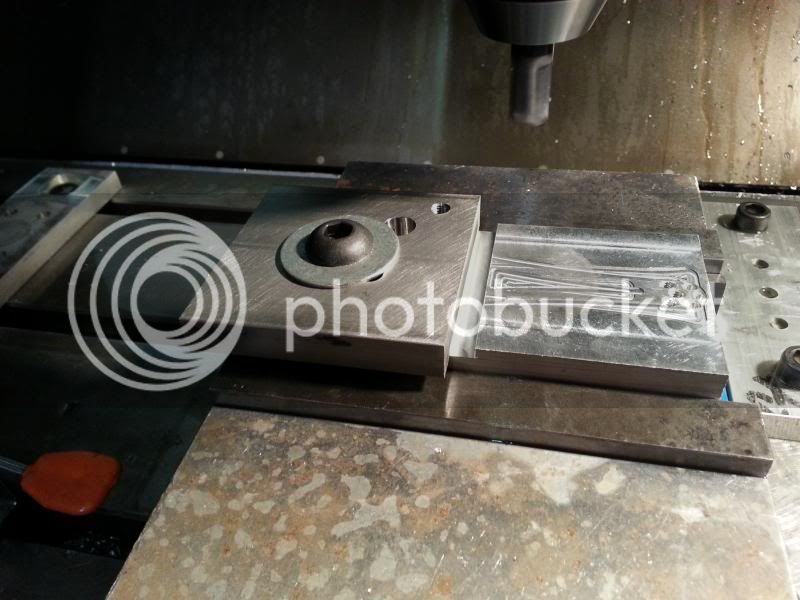
and the fork and bearings
The fork, bearings and leg all have extra material and fixture holes which will be machined off in subsequent operations. The setup allowed all the parts to be machined using the same machine zero, which worked well. The only issue I encountered was the screws not quite being equal to the task of holding the fork down during machining, and it moved around a bit, but the damage is only cosmetic and it should be salvageable. Next up - cleaning up and doing remaining operations on the parts I have so far, then starting in on the base plate.
-Neil