- Joined
- Feb 25, 2008
- Messages
- 464
- Reaction score
- 5
Technically this engine may be a motor and so is not entirely appropriate to this site. Here goes anyway.
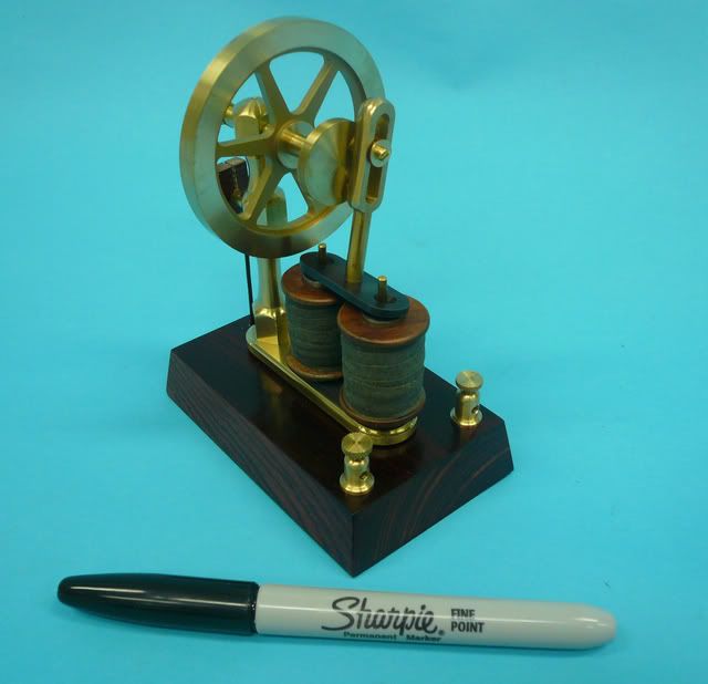
The engine can best be described as an electromagnetic rocker. It is loosely based on early (circa 1860) models of devices developed during the transition from steam power to electrical power.
The engine base is 4 in. x 2.5 in. and the flywheel is 2.5 inches in diameter. Each coil is wound on a 5/16 core with 300 turns of 22 AWG magnet wire.
In the following video, the motor is running on a 6V lantern battery. Speed is about 340 rpm.
[ame]http://www.youtube.com/watch?v=vQkI2UcCeK8[/ame][youtube=425,350]
Its a good runner, but contact pressure and timing are really touchy. If I were building it again, Id figure out a more precise method of adjusting the contact position and pressure. Also, Id make it a double contact so it would have reverse.
As far as the build goes, theres really nothing too unique. However, a few things that might be of interest are:
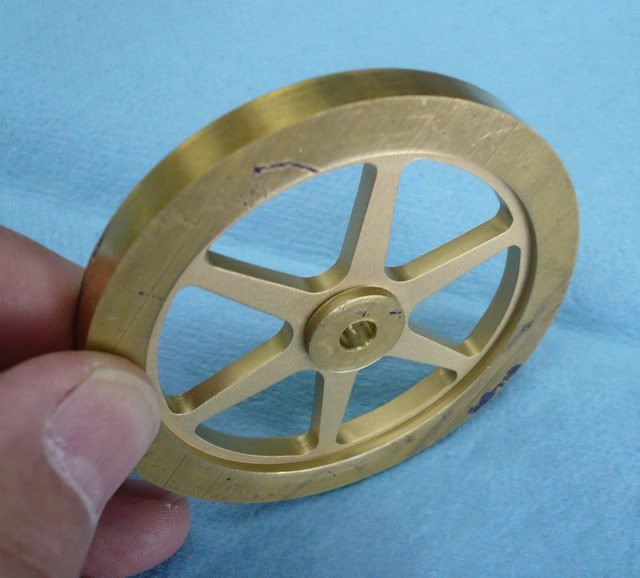
Flywheel
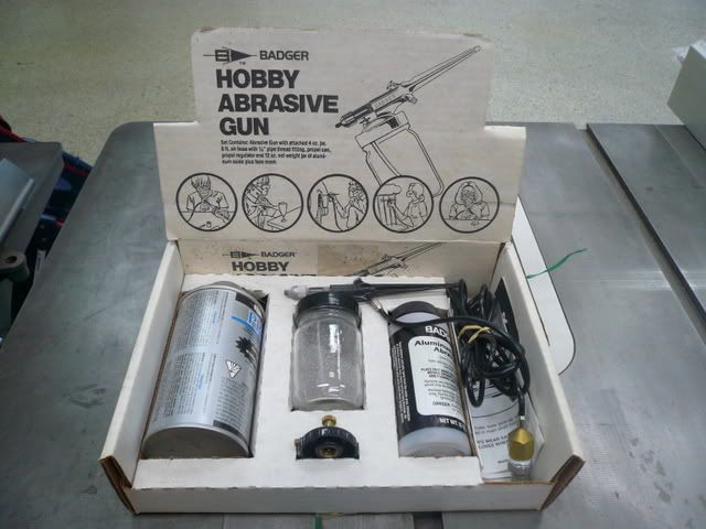
Flywheel construction followed Bogstandards treatise found elsewhere on this site. When it came to bling though, instead of painting or polishing the spokes, they were beadblasted. I used a little hobby air eraser I got at a swap meet. I like the texture and it contrasts nicely with the polished rim (photo is pre-polish).
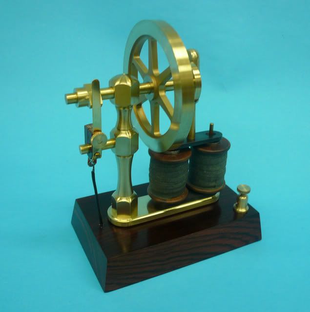
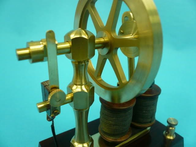
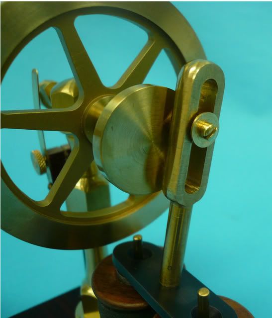
Upright
The upright was my first shot at free-form brass turning. I started with a piece of brass hex. First I cut the major diameter and then used the parting tool to cut the minor diameter of the curves.
Then I moved to the wood lathe and shaped the curves using HSS wood turning tools. The lathe was run at slow speed (500 rpm in my case) and I made very light cuts. It worked pretty well and I wouldnt be afraid to try a more complex shape. The key is keeping a negative rake.
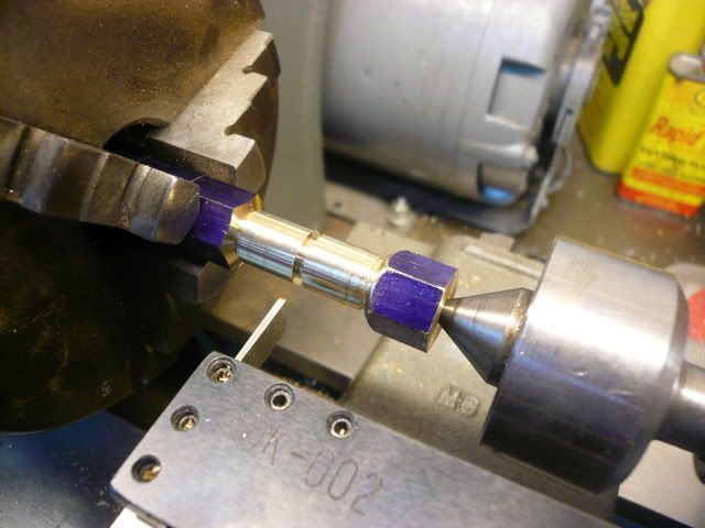
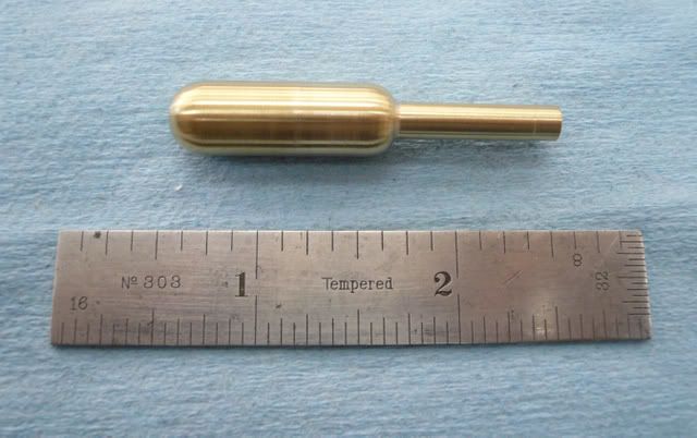
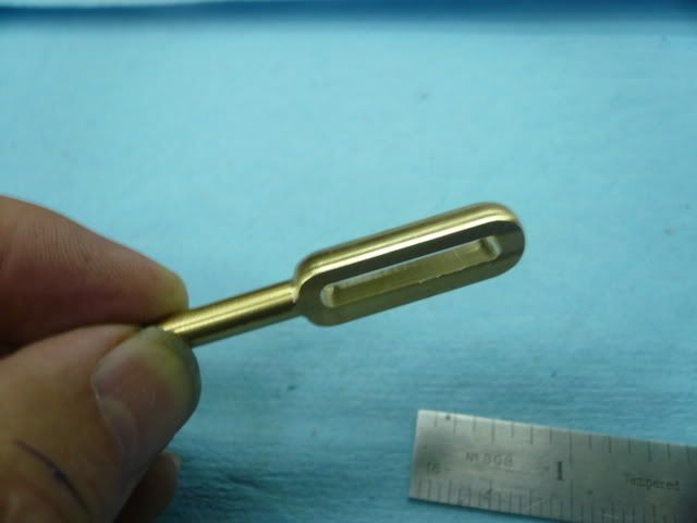
Pushrod
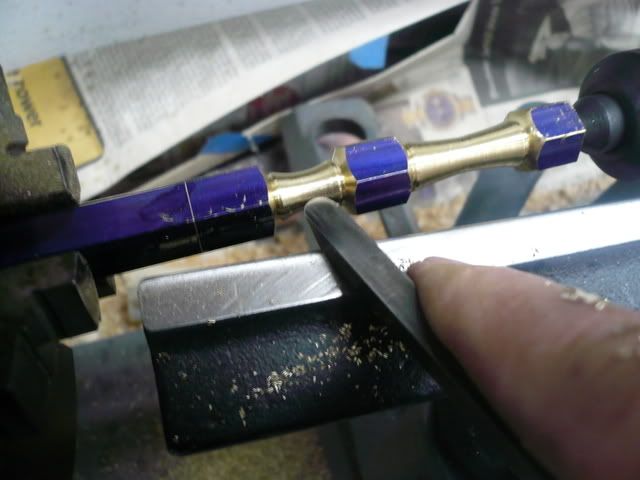
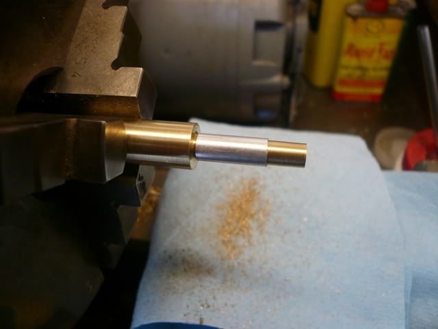
The pushrod was fabricated as shown in the following photos. The part was first turned as a cylinder and the ends rounded with a file.
A very minor tip When I filed the lower round, I slipped a piece of tubing over the small shaft to protect it from the file.
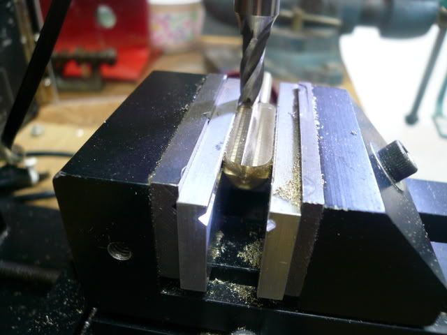
The flats were milled using soft jaws in my mill vise. Did one side, then flipped it over.
Cut out the center,
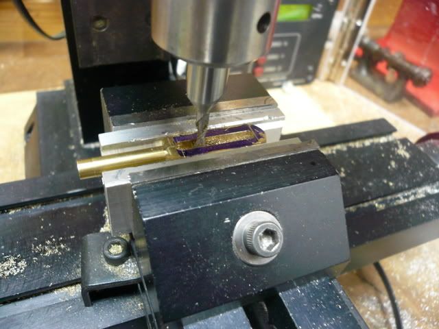
and, voila!
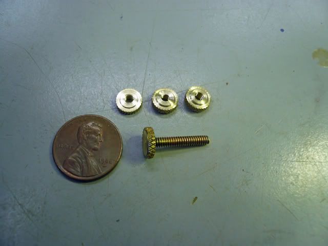
Terminal Screws
I wasnt up to attempting single-point 4-40 threads so the terminal screws were made as an assembly. The screw head was turned, tapped, knurled and parted off.
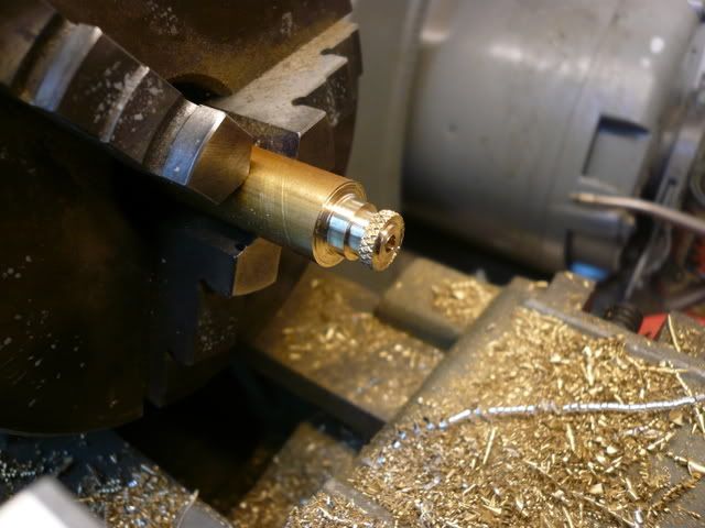
Then I screwed it on a 4-40 screw, soldered it and faced it off.
This is an overly long post, so thanks for bearing with me. More importantly, thank you all for sharing your knowlege with us. This site is fabulous. Im happy to answer any questions you may have.
Regards,
Dennis
The engine can best be described as an electromagnetic rocker. It is loosely based on early (circa 1860) models of devices developed during the transition from steam power to electrical power.
The engine base is 4 in. x 2.5 in. and the flywheel is 2.5 inches in diameter. Each coil is wound on a 5/16 core with 300 turns of 22 AWG magnet wire.
In the following video, the motor is running on a 6V lantern battery. Speed is about 340 rpm.
[ame]http://www.youtube.com/watch?v=vQkI2UcCeK8[/ame][youtube=425,350]
Its a good runner, but contact pressure and timing are really touchy. If I were building it again, Id figure out a more precise method of adjusting the contact position and pressure. Also, Id make it a double contact so it would have reverse.
As far as the build goes, theres really nothing too unique. However, a few things that might be of interest are:
Flywheel
Flywheel construction followed Bogstandards treatise found elsewhere on this site. When it came to bling though, instead of painting or polishing the spokes, they were beadblasted. I used a little hobby air eraser I got at a swap meet. I like the texture and it contrasts nicely with the polished rim (photo is pre-polish).
Upright
The upright was my first shot at free-form brass turning. I started with a piece of brass hex. First I cut the major diameter and then used the parting tool to cut the minor diameter of the curves.
Then I moved to the wood lathe and shaped the curves using HSS wood turning tools. The lathe was run at slow speed (500 rpm in my case) and I made very light cuts. It worked pretty well and I wouldnt be afraid to try a more complex shape. The key is keeping a negative rake.
Pushrod
The pushrod was fabricated as shown in the following photos. The part was first turned as a cylinder and the ends rounded with a file.
A very minor tip When I filed the lower round, I slipped a piece of tubing over the small shaft to protect it from the file.
The flats were milled using soft jaws in my mill vise. Did one side, then flipped it over.
Cut out the center,
and, voila!
Terminal Screws
I wasnt up to attempting single-point 4-40 threads so the terminal screws were made as an assembly. The screw head was turned, tapped, knurled and parted off.
Then I screwed it on a 4-40 screw, soldered it and faced it off.
This is an overly long post, so thanks for bearing with me. More importantly, thank you all for sharing your knowlege with us. This site is fabulous. Im happy to answer any questions you may have.
Regards,
Dennis