Kaleb
Senior Member
- Joined
- Jan 3, 2010
- Messages
- 272
- Reaction score
- 27
While looking on eBay, I have seen plenty of components like linear slides, ballscrews and trapezoidal (like ACME) threaded rod and nuts being sold for people building their own CNC routers. This made me think; might it be feasible to design and construct a small milling machine using some of these components? If so, I could design it with the features that we engine builders find useful in a mill, and also try to get around some of the problems associated with the commercial mini-mills.
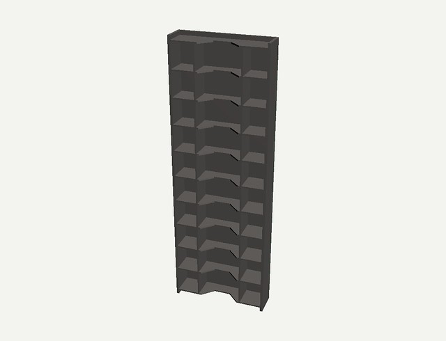
So, what sort of mill should this be? Well, I have been thinking of designing what is essentially a scaled-down version of this:
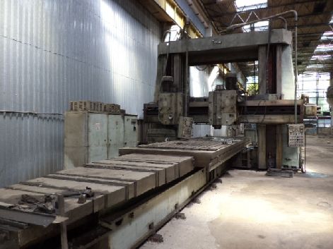
which is known as a plano-mill because of its similarity to a metal planer, which is essentially a shaper with a moving table.
My plan is to use two Hiwin linear guide rails running in parallel as the slideways, with the table running on at least four of the matching carriages. Here's an eBay listing for a length of the rail for those who don't know what I'm talking about: http://www.ebay.com.au/itm/HIWIN-HGR30-600mm-LINEAR-MOTION-RAIL-GUIDE-SHAFT-CNC-MACHINE-SLIDE-BEARING-/291086767135?pt=LH_DefaultDomain_15&hash=item43c61f941f
I'm still not sure whether to use ballscrews, as they are costly, and might be somewhat difficult to use with a handwheel due to the fact that they advance 5 or 10mm per turn. They would however make climb milling easier since there's no backlash to worry about.
I intend to fabricate the bed and columns out of heavy steel plate and bar, which should hopefully make this thing nice and rigid for its size.
So, what are your thoughts? Could this be a worthwhile project, or is it just an expensive pipe dream that would never work out in the end?
So, what sort of mill should this be? Well, I have been thinking of designing what is essentially a scaled-down version of this:
which is known as a plano-mill because of its similarity to a metal planer, which is essentially a shaper with a moving table.
My plan is to use two Hiwin linear guide rails running in parallel as the slideways, with the table running on at least four of the matching carriages. Here's an eBay listing for a length of the rail for those who don't know what I'm talking about: http://www.ebay.com.au/itm/HIWIN-HGR30-600mm-LINEAR-MOTION-RAIL-GUIDE-SHAFT-CNC-MACHINE-SLIDE-BEARING-/291086767135?pt=LH_DefaultDomain_15&hash=item43c61f941f
I'm still not sure whether to use ballscrews, as they are costly, and might be somewhat difficult to use with a handwheel due to the fact that they advance 5 or 10mm per turn. They would however make climb milling easier since there's no backlash to worry about.
I intend to fabricate the bed and columns out of heavy steel plate and bar, which should hopefully make this thing nice and rigid for its size.
So, what are your thoughts? Could this be a worthwhile project, or is it just an expensive pipe dream that would never work out in the end?