Carbide toothed saw and diamond wheel tool centre - new project

Home Model Engine Machinist Forum

Help Support Home Model Engine Machinist Forum:

This site may earn a commission from merchant affiliate links, including eBay, Amazon, and others.
Thanks for that Ian, I'll give it some thought....What I intend to do now is to complete the build then remake some items that always will need redoing with some use.

MM
 
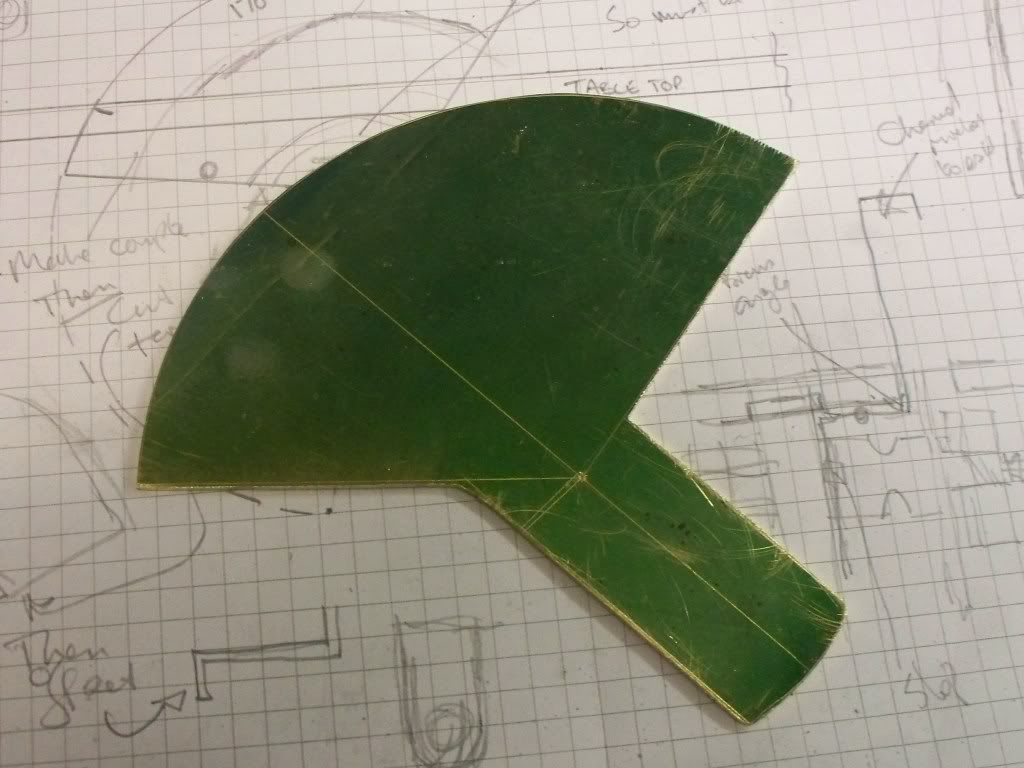
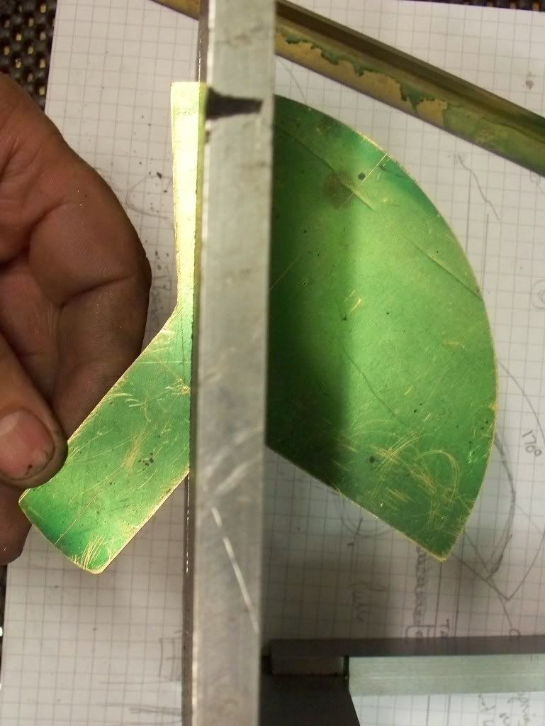
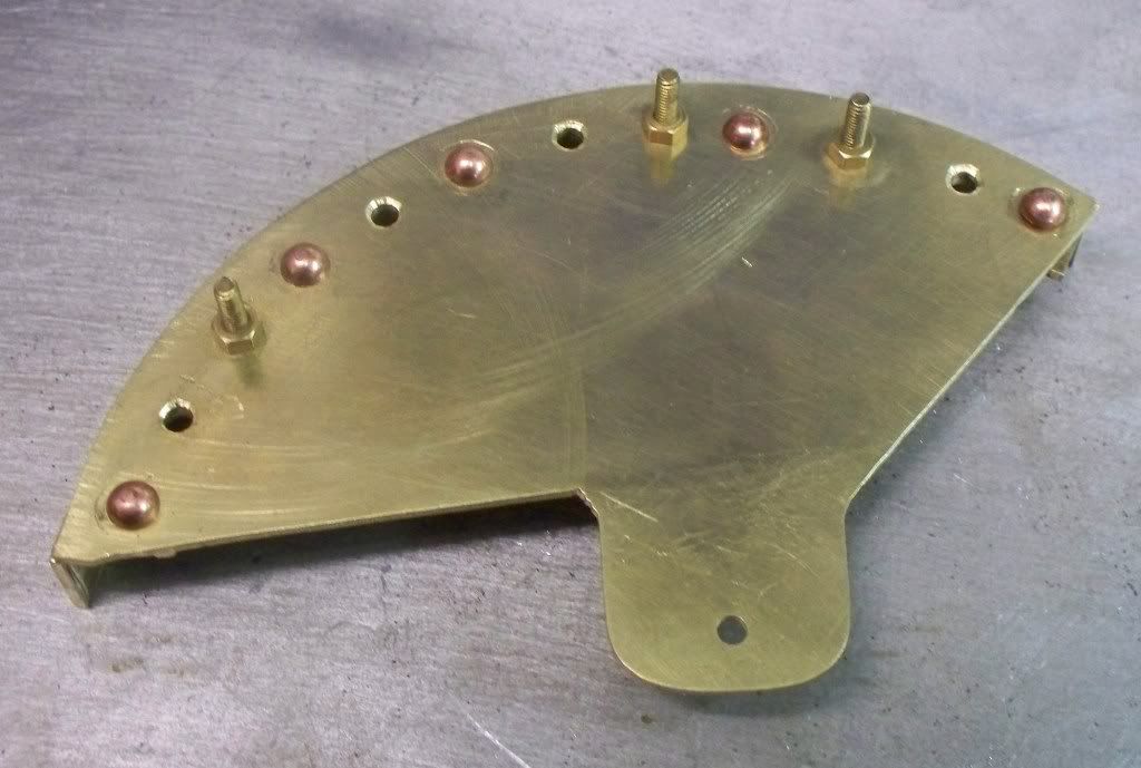
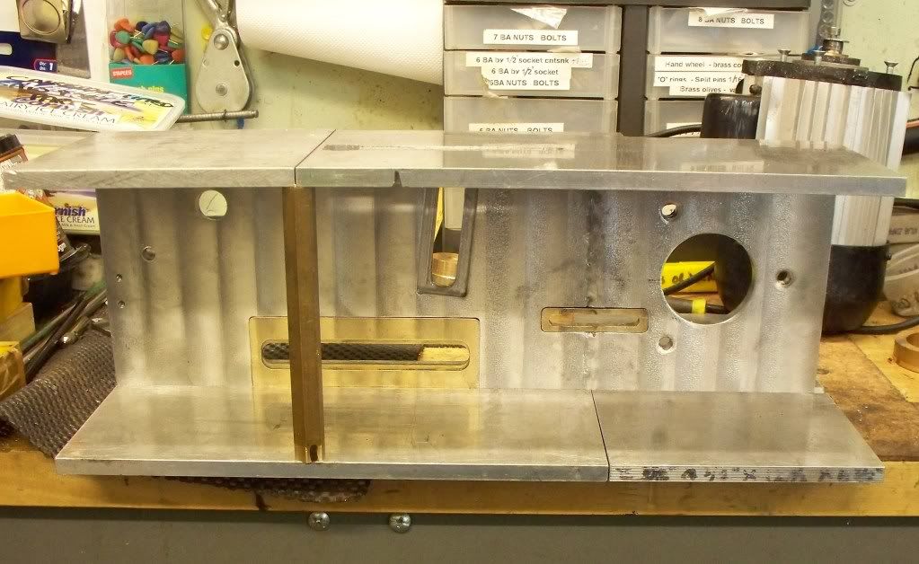
Over the last couple of sessions I have made some progress on the saw table project. Today I completed the quadrant for the saw height adjustment and assembled all the parts to date. I decided that the next job would be to give the back plate a little ‘clean up’ and used a wire brush in the milling machine to polish off the marks that naturally occur when making an item.

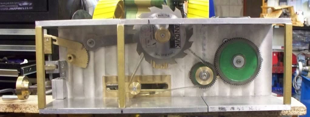
Now that the mechanism was complete it allowed me to make up the drive belt which I found more difficult than expected. I tried out the process on a couple of scrap pieces and simply melting the ends produced all sorts of results. After some practice I managed a reasonable result that allowed me to make a good joint on the proper belt.
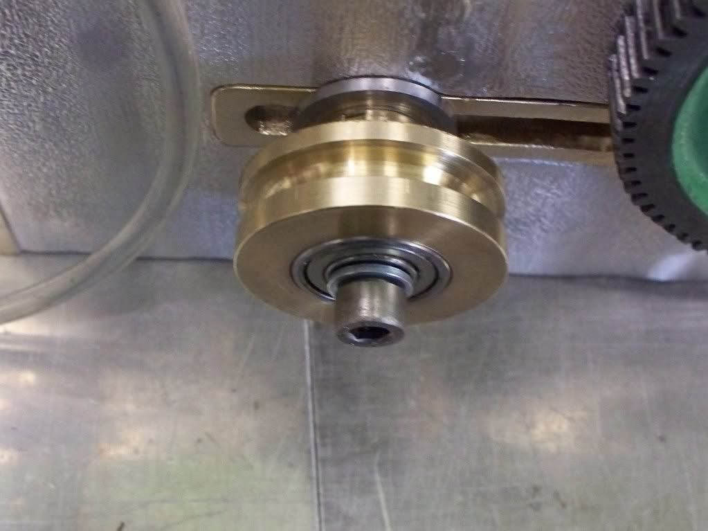
When running the system for the first time I was pleased that all turned as expected and the drive from the belt worked with varying tension settings. After 30 seconds or so the whole thing stopped dead. The pulley that holds the gear wheel on has seized up.

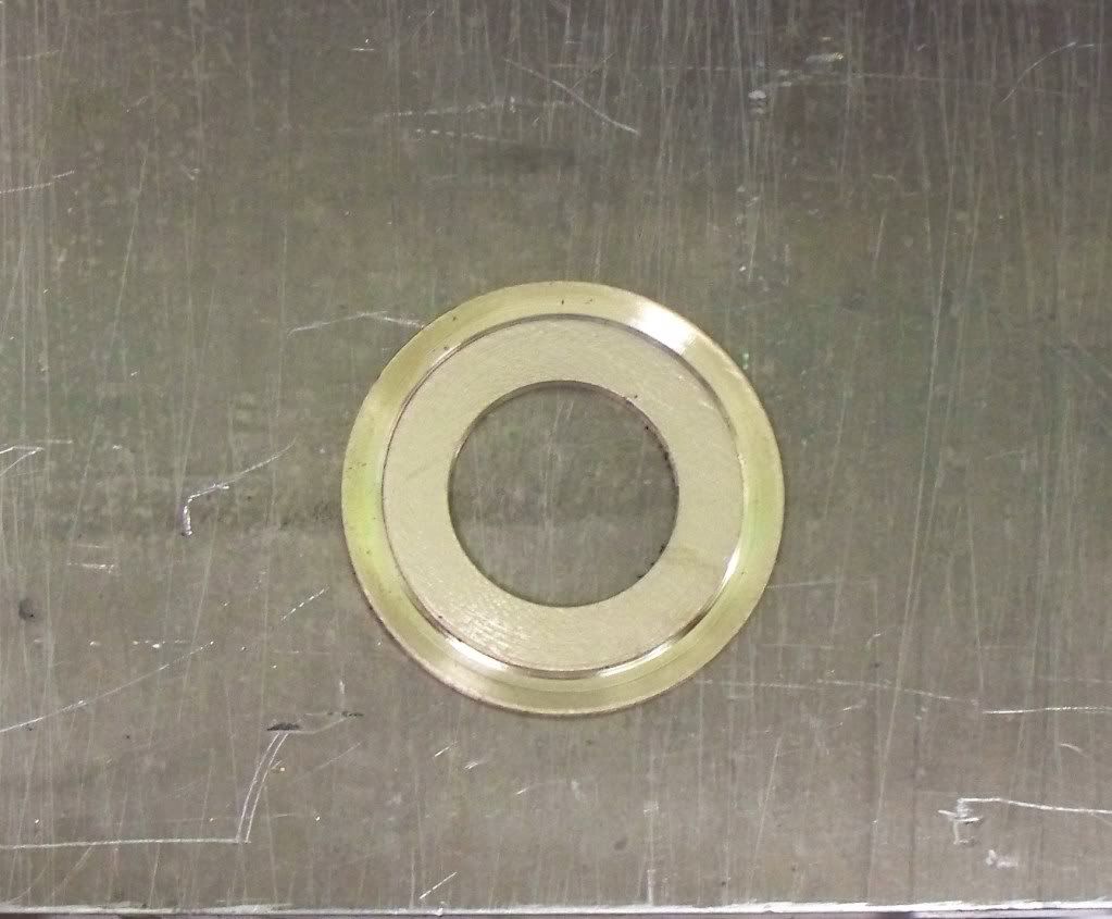
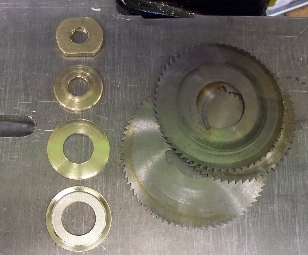
On investigation the bolt holding the pulley on had tightened itself up sufficiently enough to stop it. The design was not meant to rely on any securing method to impact on the pulley turning. I had turned the shaft so that it extended beyond the brass pulley and in theory it should have worked. When looking at the problem further I thought that perhaps I had not left enough showing and all sorts of ideas came to mind particularly taking some of the pulley width off. However the answer was simply to change the washer on the end of the shaft from one that covered the whole bearing to a much smaller one that only covered the end of the inner shaft.
http://i353.photobucket.com/albums/r379/brixham-engineer/saw%20%20table/19062009sawtable002.jpg/img]


This cured the problem so the motor was started again and run for a couple of minutes before the saw blade stopped again. This time it was the pulley that holds the saw blade that had seized. Looking closely it was the shaft that was binding and I simply took a couple of thou off the end of the shaft being careful not to reduce the shaft part that the bearing sat on.

[IMG]http://i353.photobucket.com/albums/r379/brixham-engineer/saw%20%20table/19062009sawtable002.jpg

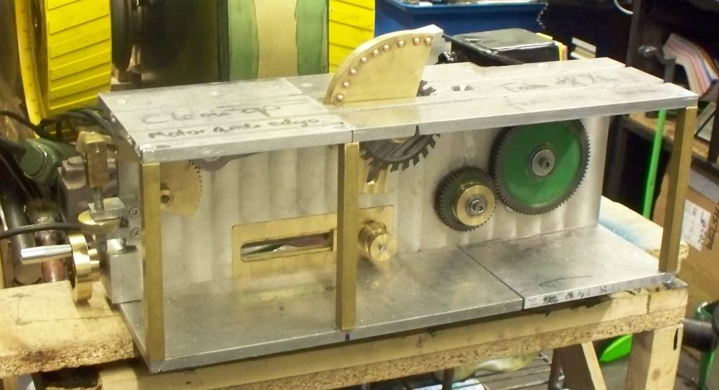
The motor was started again and all ran as it should do. I then varied the height of the blade to the two extremes and tensioned the belt to suit. All ran well and I will now be able to cut the studding used for the blade adjustment.
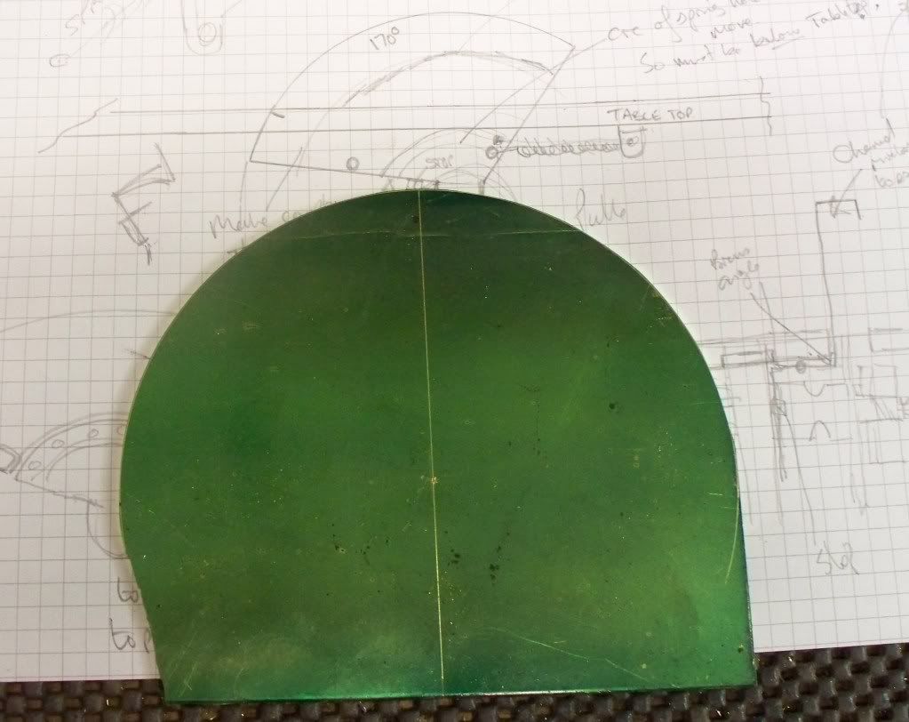
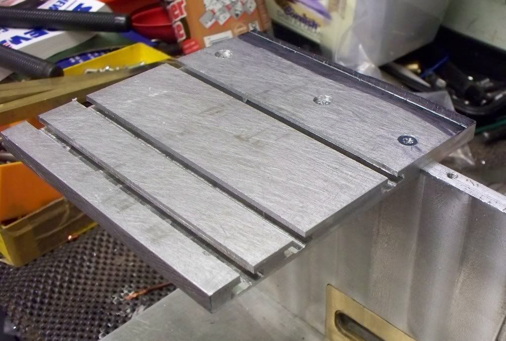
Suitable pleased I thought I would make a start on the top plate and soon produced the first part of the top with the slot for the diamond grit and two sizes of saw blade to fit in. This was placed in situ and I thought I would just ‘try’ the blade to see how it would cut. I am glad I did since I will have to ensure that any clamping system will take into account the kick back effect found when cutting some brass sheet.

I then tried a ¼” diameter steel bar and you can see the results in the pictures. It wasn’t really a proper test since the bar wasn’t held properly but it actually cut better then the brass sheet. I have no doubt about the blades ability to cut. Then I tried the end of the HT steel that bar that started the whole project and was really pleased to see the small cut that appeared in the end of the bar! It will cut it and that’s good news.

So today’s session really is the beginning of the end………………………………….

To make a change I thought I would show a short video....don't forget there is a lot more to do yet!


"http://www.youtube.com/v/wtg0Qh0peeg&hl=en&fs=1&"


Mike,

I can't see the images or video in your latest post. Not sure if it's me but the still says image deleted and the video is only a set of quotation marks.

I would like to see what you've been up to. ;)

Best Regards
Bob
 
MM
Ben using a carbide saw as slitting saw for years. Using the thing for steel on down to brass and alu.
But only in the mill with steel and brass. I would not think about using it as you have in mind.
I can tell you with steel when you down at the last 10 thousand that piece comes flying off with no mercy.
You can search under slitting saw and see the blade right there.
be care full MM

Hilmar ??? ???
 
Maryak said:
Mike,

I can't see the images or video in your latest post. Not sure if it's me but the still says image deleted and the video is only a set of quotation marks.

I would like to see what you've been up to. ;)

Best Regards
Bob

Hello Bob, the images and video shows on mine so i don't know. Also it seems Hilmar has seen the images and video......


Hilmar said:
MM
Ben using a carbide saw as slitting saw for years. Using the thing for steel on down to brass and alu.
But only in the mill with steel and brass. I would not think about using it as you have in mind.
I can tell you with steel when you down at the last 10 thousand that piece comes flying off with no mercy.
You can search under slitting saw and see the blade right there.
be care full MM

Hilmar ??? ???

Hello Hilmar. I agree with you that safety in use is an issue. As I said in my text the trial has emphasised the importance of the clamping system. The ideas I have for holding the piece to be cut securely are still being formulated but will be based on 't' slots and a lead screw advancing vice so both sides ot the piece to be cut will come out the other side still being clamped.

Time will tell but if I cant get the work holding system sorted out I won't be using it! However I love a challenge and that's what the project is all about really, problem solving. Used as is then it is an accident (and a nasty one at that) waiting to happen because the blades can certainly kick back!

What I would like to say in my defence is that it is still evolving and there will be a safety guard for the blades as well the workholding system. I would not recommend using the saw in its as yet uncompleted state.
 
Right on Mike.
One thing i can tell you right now,they sure cut nice and smooth.
Some times you could use the piece as is.
Hilmar
 
Metal Mickey said:
http://i353.photobucket.com/albums/r379/brixham-engineer/saw%20%20table/19062009sawtable002.jpg/img]


[IMG]http://i353.photobucket.com/albums/r379/brixham-engineer/saw%20%20table/19062009sawtable002.jpg

Mike I get the video, and very nice too but above is what I get for the still

http://i353.photobucket.com/albums/r379/brixham-engineer/saw%20%20table/19062009sawtable002.jpg/img][/quote]

Best Regards
Bob
 
i would really think about some way to secure the work piece in a vice of some sort that could be mounted to the table and moved with a handle of some sort . i just had bad visions of the metal coming at me and through me. brings back bad memory's of the skill saw and the steel fence post. that thing will kick out hard. please be careful. i remember that skill saw kicking back with a force that i could not hold. all i could do is let it flow by me with strong guidance from my arms and hands. maybe if it turned slow it might help too.
but i like the way it coming along
 
A short session today in the workshop and I didn’t feel up to doing anything major or critical. Overnight I had been thinking about the saw table project and a moment of possible inspiration came when I wondered what a normal slitting saw would be like in use on the saw table?

When I had a look at the saw pulley it was turned to 1” diameter and of course the slitting saws I have are 1” bore! So I decided to spend my time working out how to fit the slitting saw to the existing pulley rather than turn another (I also didn’t have another bearing). The answer I thought of was to make a washer that would seat against the pulley and have a large 1 ¼” diameter outside.

21062009sawtableandpistonandforseal.jpg


So it was over to the lathe and turn the required washer (see photo) and then see if it worked. I also needed to have a larger washer to sit in front of the slitting saw so I could use the same securing nut.

I was really surprised when trying the saw out with some brass sheet just how good it was! Now you may have been ahead of me but for sheet work I believe the saw table will be a great asset (for straight cuts only) and a real bonus for the project!

I also had a fiddle with some of the pulleys to get them running for a long period and called it a day surprised with the advance in usability of the project which is already good. Next will be to try the diamond grindstone and what sort of fittings I will need to make to grind turning tools. Once this trial period has been completed I will fit the top and bottom sheets to the back plate and securing everything together.

For the work holding I intend to cut either two or three ‘T’ slots along the top table. After making a couple of basic work holding tools I will put the project to one side and get back to building the Seal engines. When I need to use the table I will develop tooling each time to suit the task and over time this should build up a flexible system.

21062009sawtableandpistonandfors-1.jpg


Hello Bob, hopefully the picture you missed will be shown below.....I hope....

19062009sawtable002.jpg


Mike,

Thanks for taking the trouble to repost the picture. It has appeared in your last post. :bow:

Best Regards
Bob

 
No problem Bob, anything for you.................

Today's efforts:

Overnight I considered how to make and fit a safety guard for the saw table project. So at breakfast time (0600) I took pencil and paper in hand and roughed out a design that I thought may work. When going out into the workshop my first task was to see what materials I had that could be used for the design.

So armed with some brass angle and sheet brass I started to mark out my design. I must admit it would have been easier if I had made the guard from stiff cardboard as I have done previously but for some reason I forgot to do this until I was a fair way through the making of the guard.

Fortunately the spare blades for the Proxxon bandsaw had arrived from Chronos and it was really nice to cut some brass sheeting with a new blade! It reminded me that the new saw table would be ok for some tasks relating to sheeting (differing materials) but I should forget my trusty Proxxon.

After making the brass back plate for the guard I fiddled for quite a while trying to work out how I could fit it without the guard fouling the blade. I wanted to offset the pivot point to clear the end of the saw pulley but the circle of movement was then moved. In the end I decided to adjust the slot in the top table to give me the clearance required. Simple to write but that was an hour or so gone!

To form the top of the guard I decided to use brass angle and to allow the curvature required I cut slits at ½” intervals using the bandsaw and then drilling holes in the centre of each newly formed tab.

I mulled over whether to silver solder, bolt or rivet the angle in place and in the end thought that copper rivets against a brass fitting would contrast nicely when it came time to add some ‘bling’. The brass angle was held in place with 4 equidistant temporary 4BA bolts whilst all the holes were drilled before the inside holes were countersunk so the copper would have somewhere to go. This will help the rivets hold the two parts together.
With the outer part of the guard in place the final slotting of the table top could be done and a piece of brass angle was used to form the pivot bracket. it is secured to the underside of the table top which is where I got to at the end of the session. However I may have another problem to overcome since I made sure the work was done when the largest saw blade is at its highest position. When reflecting on what needed to be done next time I thought that the system may not work! When the saw blade is lowered the guard does not go with it!

My initial reaction is that the guard will still serve its purpose if it sits above the blade but just on the edge so that when it is lowered it does not foul. If that isn’t a solution then I will have to rethink how the guard can be secured to the saw pivot arm. And that would be a problem!

The guard will be held in position by a spring once I have the system sorted out. Again, don’t take too much notice of the finish of the parts since it will be dismantled when finished and ‘blinged’ up then…….

22062009sawtablesafetyguard001.jpg


22062009sawtablesafetyguard004.jpg


22062009sawtablesafetyguard005.jpg


22062009sawtablesafetyguard008.jpg


Today was the first time that I could get back into the workshop for a while so I decided not to over stretch myself and just mill up the locating slots in the twp base and two top pieces.

To help speed up the process in setting up each piece I used the straight edge of the table to locate a strip of angle iron. This raised the edge up high enough so each piece rested against it and the aluminum then clamped in place. Now this is where the DRO’s (digital read out) came into there own since once I set the depth of cut and ‘Y’ axis (I set them both at zero) then it was simple to just unclamp and then replace a piece. The end results were certainly good enough for this application.

After trying the back plate into one slot, the width was adjusted then full steam ahead with an aching arm and back from all that handle turning! I have a 12v windscreen wiper motor waiting to set it up as a power feed but decided that if I went on to make that project to finish this one it would be even longer before I could get back to the pair of seal engines!

After checking that all four parts slotted into the back plate I marked out in the channels the position of holes for the securing screws. These were then countersunk before finishing for the day.

Hopefully the next session shall see me cut the ‘T’ slots in the top ready for any fixings and the uprights between the base and top cut and secured in place. This will certainly see the last phase of the project come into view at long last.


26062009sawtable006.jpg


26062009sawtable002.jpg

 
Well today I manage to finish tapping both top and bottom sets of securing bolts before making a fixture to cut the 16 or so bolts to same size. Once this was done it was over to the milling machine to firstly cut three slots before switching to the cutter to make the 'T' Slots. this is a messy job and certainly made my arm ache. I must get the power feed sorted out!

29062009sawtableandprawntraps033.jpg


I also forgot to change the speed of the milling machine and it didn't take long to for me to realise! So after changing the belts to get a much slower speed it all went well but I didn't feel up to continuing on with the long top plate. Hopefully next time it won't take too long to finish the slots. I will then make three supports from brass square bar so I can add a cover (steel) if I feel I need it.
 
Sessions in the workshop have been few and far between lately but I did manage to have good session today. I managed to get to the stage of fitting the tops and sorting out a few teething problems (such as milling two flats on the saw holding pulley).

The project now should only have another couple of sessions to complete it. That does not account for the work holding systems butt at least I have designed those for both saw blades and using the diamond wheel for grinding tool steel. Which ones will come first will depend upon what I need at that time.

The work remaining includes making the sheet steel front and side plates, making a set of spanners for changing the blades/diamond wheel. Making an extending nut to secure the blade at the correct height and finally dismantling the whole thing to clean it up and give it a nice finish. When I have explored anodising a little more I think it would look nice to anodise the top plates. We shall see.

Anyway a picture is worth a thousand words so they say, so here we are……

http://i353.photobucket.com/albums/r379/brixham-
engineer/saw%20%20table/05072009sawtable004.jpg

05072009sawtable006.jpg


05072009sawtable007.jpg

 
It has been remiss of me not to have updated the position on my saw table. It is now in constant use and really is the first major home designed (still cant loose the design and build at the same time, I want to get to using Alibre first if I can)tool that works!

I must admit though that the blade that started the project is no its main use, I found a great blade at my only local tool stockist, Tracy Tools (UK) and during a visit there I saw (sorry!) a slitting saw but with side cutting teeth. They come in varying sizes and are excellent in use.

The carbide tipped blades are ok for aluminium but as one or two on this forum mentioned, you need to watch for grabbing. Using the side toothed slitting saw at 4" diameter however feels a lot safer to use and is effective on the metal I have tried to date.

The flexibility in use is very good and vindicates (for me) the amount of time spent building it. Since the last pictures posted I have made a steel front cover and the first fixture shown below. Its use for a project I am undertaking (seperate post to follow) for this years Christmas gifts for the family. Last year I made a pair of wobbler's http://www.homemodelenginemachinist...l]34581[/ATTACH] [ATTACH=full]34582[/ATTACH]
 

Attachments

  • 100_3364.JPG
    100_3364.JPG
    1,018.3 KB · Views: 221
  • 100_3365.JPG
    100_3365.JPG
    980.3 KB · Views: 245
  • 100_3366.JPG
    100_3366.JPG
    1.5 MB · Views: 283
  • 100_3366.JPG
    100_3366.JPG
    1.5 MB · Views: 286

Latest posts

Back
Top