Bore Measuring

Home Model Engine Machinist Forum

Help Support Home Model Engine Machinist Forum:

This site may earn a commission from merchant affiliate links, including eBay, Amazon, and others.
Hi Ozzie,
Yes I broached it. Through the years I have purchased several different size broaches for making key slots for my model engines, .062, .094 and .125. They come in handy for other projects like this one.
gbritnell
 
Hi,

While Marv is correct in stating that if you measure an internal diameter with the inner jaws of vernier calipers there will be an error due to the fact that the jaws do not come to a knife edge, this error is not usually a problem.

My calipers have flats on the inner jaws that are 9 thou wide (call it 10 thou to make the sums easy). This gives the following theoretical errors:

Using these calipers to measure a one inch hole will give an error of two tenths.
Measuring a 0.5 inch hole the error becomes four tenths.
The error only really becomes an issue when you get down to hole less than 0.5 inch diameter - at 0.25 in dia. the error is eight tenths.

If you are worried about fractions of a thou, you will not be using these types of calipers to make the measurement anyway.

The real problem with using the vernier jaws is that you cannot assess bore taper.

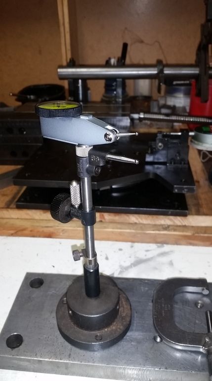
Despite over thirty years in the business (15 as a machineshop instructor) there are still situations where I find it difficult to compare sizes with bore gauges. This is often due to the difference in "feel" due to the difference in surface quality between the bore and the reference (for example, comparing a turned bore with the surface of the micrometer anvils). To get round this inconsistency I made a DTI based gauge similar in concept to the ones shown earlier in this thread which removes the requirement to match the feel of the bore by relying on the DTI stylus spring to provide a constant pressure.

A further requirement that I had on the gauge was that it should have a reach of 1.5 inches to allow bore taper to be assessed.

My gauge is based around a design published in Model Engineer magazine in the 1980s and is designed to work from 2 inch bore (where my "stick" micrometer stops) down to under 0.4 inch.

By machining the contact pad on the swinging arm in-situ the tool reads accurately to one thou over the whole range of the DTI (0.25 inches).

The DTI reads "backwards" due to the operation of the swinging arm so I remarked the dial - in the case of the main dial this involved changing a 5 to a 15 and a 15 to a 5 which was quite simple. Reversing the numbering on the small turns counting dial was too fiddly and I produced a new paper scale.

The DTI shown can be replaced with a metric DTI.

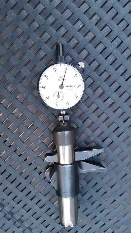
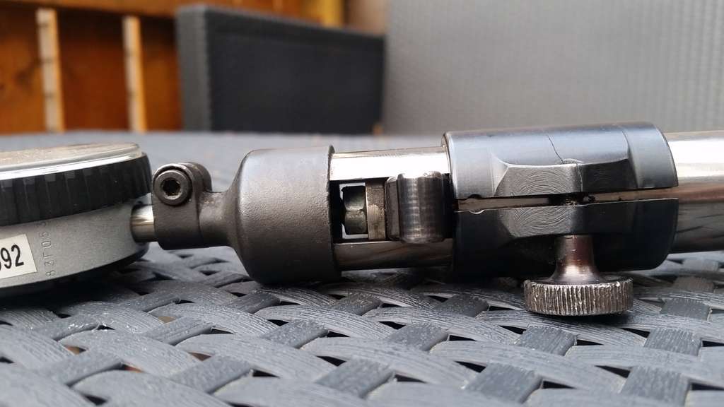
Gauge set to maximum

1-max.jpg


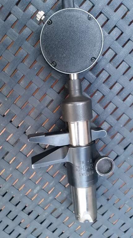
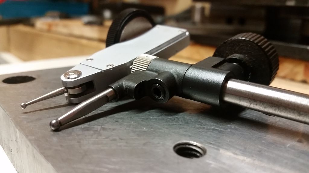
Gauge set to minimum
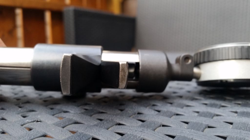
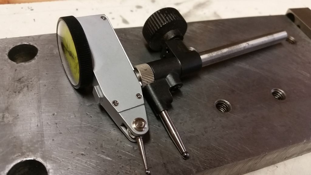
2-min.jpg


Gauge parts

6-parts4.jpg


3-parts1.jpg


4-parts2.jpg


5-parts3.jpg


Ian.
 
Ian, that is a very neat gauge. It's not like I need another one but I'll probably make one like yours also. The only thing I would make a little differently would be to machine a little drill rod hemisphere with a stem, harden it and insert it into the end to give a finer feel to the high point if you know what I mean. I see you have somewhat of a radius formed on the ends of your levers.
gbritnell
 
Hi,

I agree the anvils should be machined to a better finish and hardened.

As I hinted in my previous post, I cheated when making the gauge anvils and the pad that touches the DTI stylus.

I simply filed the gauge anvils to a radius that ensured they would work within the minimum diameter the gauge was designed to measure (they ended up about 1/16th rad.) then machined the pad to suit using the following method:

Assemble the gauge without the DTI and set the unit in the mill with the DTI axis vertical.

Set the gauge jaws at maximum open and measure the distance between the jaws with a mic.

7-cal1.jpg


Clamp up and run a little end mill across the pad.

8-cal2.jpg


Close the mic by 20 thou and raise the end mill by the same amount and repeat.

Do this until you reach the minimum open setting for the gauge jaws.

You end up with a series of very small facets which are reduced to a smooth curve with a few strokes against some very fine emery paper held on a glass plate

This process compensates for all the lumps and bumps due to the imperfect shape of the anvils.

Ian.
 
Aha! just like when I make my camshafts.
gbritnell
 
Boy, there are sure some good ideas in this thread! Thanks George, John, and Ian, for sharing your methods.
I've become very used to using tele gauges to measure inside diameters over the years, and am even half-way good at it, but what you fellows show here would be a great addition to my shop without breaking the bank on buying an inside mic.

Dean
 
Hi,

I've read this thread with interest but I don't think I've seen an inside micrometer mentioned:

mike4.jpg


I picked up this Mitutoyo unit secondhand on EBay about a year ago for around £20. Although I have T-gauges and small-hole gauges I've never really got the right "feel" for them so I thought the ratchet action of the micrometer would compensate for that. TBH I haven't had the chance to use it on a serious job yet but testing it with various standards suggests it's accurate. The only obvious problem I can see with this device is that it only measures bore diameter near the entry — taper in the bore wouldn't be detected. Are there any other disadvantages?

Joe
 
Joegib,
For even more accuracy you can set the I.D. mic. and measure across the anvils with a rachet equipped .0001 micrometer. No it still won't measure bore taper, But lapping would take that out.

Pete
 
Maybe an old post, but i have something similar to those great shop made tools in this thread. Its called an Unimeter. Even though this one is branded S.P.V i have one that is identical made by C.E. Johansson (CEJ) that i cant tell apart except the branding.

Very usefull tool. I also have a similar type to measure from the outside that is made by Helios Preisser, Germany.

The smallest diameter you can measure with this one is 28mm. The SPV is cut down. I use this one for holes up to 60mm. Theere is also a extension shaft so you can measure bigger holes. For smaller holes i use a Mitutoyo 12-20mm bore gage or pin gauges if i can find the right diameter. I have two boxes full, maybe around 200-300 CEJ pin gauges. One day im gonna sort them. Atleast thats what i tell myself :D

n5t99C.jpg


wxIuRt.jpg


4nMkGi.jpg


bVbPRT.jpg
 
Another idea for a cylinder guage is below. You would need one for a particular diameter, but it is very accurate. It would be especially useful for people making a multicylinder engine.

Lohring Miller

View attachment 4bidg.pdf
 
Some really interesting gadgets presented here.

How about initial setup of boring heads? Do you guys have a favourite method or 'pre-measurement' jig that facilitates knowing what the cutter tool sweep (=diameter) is accurately right from the start? I do the cut + measure method, but I thought it would be handy to 'know' the value with higher degree of accuracy beforehand & correlate that to the dial setting when its more of a finishing operation vs. progressively enlarging a bore. I've gotten tricked by cutting tool spring back or burr/finish giving me a false bore measurement. My crude method is clamping an old set of verniers in the mill vise & making contact at two max X-deflections. I envisioned a jig like attached sketch, but maybe there is a better method?

5-3-2015 0003.jpg


5-3-2015 0002.jpg


5-3-2015 0000.jpg
 
I generally set the boring head and then measure. Take an edge finder to the fixed outside edge of the mill vise. Zero your reading, then set your boring head to the radius of your hole to be.
Now adjust the cutting tool to just touch the vise jaw. Bore the hole.
Just remember set the radius distance, not the diameter.
 
I have used a simple method for bore measurement for years
It requires a good mike, and a good set of adjustable parallels
Cheap parallels are not consistent in corner construction ( radius/chamfer) , smoothness, or parallelism.
Insert the parallel and expand it, then read across the diagonal corners.
The parallel will center itself and also tell you the bore is tapered or bell-mouthed by movement.
(That is, it will be tight inside and yet pivot at the bore entrance.)
Works great and does not require special tools....although I do like Georges' measuring tool approach as well
Rich
 
Gus is very ham-fisted when it comes measuring i.d. when boring engine cylinders. Digital Caliper gave me inconsistent readings. Bought a set of M.I.C. aka Made in China 20-----40mm, 3 point HoleTest Micometer from ArcEuroTrade,UK. Came with Ring Gages too. So far so good. Mitutoyo and Starrett cost me a bomb. With a price of one Mitutoyo Inside Mike ,I bought a set of 4. Tried asking for a 5--10% discount but Mitutoyo dealer won't budge. $$$$ came from Dividends. Retirees must watch their savings.

IMG_2824.jpg
 
I just liked gbritnell's tool so much i put together one myself.

That's really nice!

- the black bits look like maybe off a commercial accessory? Did you make it or modify it? Can you elaborate?

- I didn't have much luck finding a tiny dovetail cutter, but maybe I'm looking in the wrong place. Did you make the cutting tool or buy it?
 
- the black bits look like maybe off a commercial accessory? Did you make it or modify it? Can you elaborate?

I cant really say i made it. Its just put together with stuff i had laying around. Yes, the black bits are from some kind of measuring rig made by CEJ. Came with a lot of tooling i bought sometime ago.

UjCgag.jpg


y1bptt.jpg


vgYK4w.jpg


The 8mm hardened rod was drilled out with a carbide spot drill to fit the 4mm shaft of the Mitutoyo dovetail mount. The Mitutoyo mount was pressed into the hardened rod. Here is how the mount looks:

72062000028.jpg


The rod mount for the "adjustable" contact point was bored out. So it fits around the dovetail thumb nut. Everything else was just put together for setting up the tool. Its really easy to use and i can measure holes down to 19.70mm.


...
 
Back
Top