Bevel Gear Cutting With Involute cutters

Home Model Engine Machinist Forum

Help Support Home Model Engine Machinist Forum:

This site may earn a commission from merchant affiliate links, including eBay, Amazon, and others.

kcmillin

Project of the Month Winner!!!
Project of the Month Winner
Joined
Jan 19, 2010
Messages
1,193
Reaction score
41
I have recently purchased a set of 48DP 14.5 degree involute gear cutters.

Are there any formulas for the required dimentions of the blank, like there is for standard gears?

What should the major diameter be? And how do you determine what the major diameter is?

Are the angles arbitrary?

Can I even cut bevel gears with involute cutters?

Sorry for so many questoins, I just want to get the most out of my investment. Gears are really fun to make.

Kel
 
Kel,

Chapter 5 of Ivan Laws "Gears and Gear Cutting" (Workshop Practice Series #17) has a complete description of how to set up bevel gears. Chapter 11 covers how to cut them in the home workshop.

I have just dusted it off as I am about to replace two stripped bevel gears in a friends Radial arm saw (saw head seized in the support column + non-tech inclined user = gears with no teeth left).

Cheers,

Adrian
 
Kel,
Kozo's book "BUILDING THE CLIMAX" has a chapter on cutting skew bevel gears of uniform tooth height with involute cutters. Bevel gears are just a special case of skew bevel gears where the shafts are not offset.

I have cut about 65 sets of bevel gears with 48 DP cutters for model engineering projects using a very similar method and it is not a lot more complicated than cutting straight spur gears, although it is a little more time consuming as at least 3 passes will need to be taken for each tooth.

I can help you with some of the math if necessary. A knowledge of trigonometry is helpful, but for straight bevel gears only a table of tangent functions or a simple scientific calculator to look up the tangent functions would be necessary.

Gail in NM
 
Kel,
I have heard the Ivan Laws book is good but I do not have a copy.

The book I use is "Gear Design Simplified". I think the best method for standard gear cutters is the parallel depth method. The angle of the cutter path is the same as the face angle in this method and it works fine for gears with relatively short face lengths.

Steamer put a old but good gear book in the download section that covers bevel gear rules. I do not think that it covers the parallel depth method but it is a start.

And yes there are rules for the blank size and angles. Nothing is arbitrary with gears it is all math in metal with gears.


Dan

Edit: I see that Gail mentioned Kozo's Climax gears and the uniform tooth height method is another name for the parallel depth method.
 
Cool thread!

I've been thinking about bevel gears for a little fun project I'm thinking of.

I forgot I have the #17 Workshop Practice Series!

"Sorry dear...I'm reading" ;D
"Uh...no...no I'm not...I can read later."

 
Thank you ball for your replies. I will be looking for these books.

I don't have any particular projectsr in mind. I just want to get the most out of my cutters. Looking forward in a way.

What I am basically looking for is a formula to determine size of the blank, and also to find the center "Distance" or close to it. I know this can be changed easily be using shims to get the backlash right.

I have a set of formulas I can easily understand for straight gears.

Am I looking for something that doesn't exist? Is there more to it than I understand.

Gail, I'm not sure what the difference between skew bevel gears and bevel gears is.

Is a skew gear when the pinion is not inline with the center of the ring gear?

I just want simple little gears I can use for 90 degree applications.

Kel

 
Pat,
The angle of a bevel gear changes with the number of teeth for a given diametral pitch.

In the special case of miter gears which are identical bevel gears with the same pitch and number of teeth and mesh at a 45 Deg. angle, the cutting angle for parallel depth gear is 45 Deg.

As Gail mentioned other combinations can be simply worked out with a cheep calculator. If you know the pitch and number of teeth the pitch circle for both gears can be calculated.

The simple way to lay out the pitch cones of a bevel gear is to draw a rectangle with the pitch diameter of one gear on two opposite sides of the box and the pitch diameter of the other gear on the other two sides. Draw a line through both sets of corners that cross in the middle. Now you have the center point and your pitch cones. The angle to set the cutter for the parallel depth method is the pitch angle hence the name parallel depth.

The depth of cut is the same as for a spur gear. I hope this helps, but the books mentioned will help.

Dan

 
There is an excellent technical arcticle in the July-August edition of Home Shop Machinist on making bevel gears. It was written by Ed Hume, a local member of the Austin Metal Working club. I've seen the gears he makes for his steam locomotives and the work is first rate.
 
kcmillin said:
I'm not sure what the difference between skew bevel gears and bevel gears is.

Is a skew gear when the pinion is not inline with the center of the ring gear?

I just want simple little gears I can use for 90 degree applications.

Kel,
Yes a skew bevel gear is when the two shafts are not in the same plane so they can cross over each other. The book Dave put in the download section covers skew bevel gears which are very rare and are not a type found in production today so they have to be made in the shop. Kozo's write up on this type of gear and how to make them in the shop is very worth while.

Ed Hume made his own multipoint gear cutter to take Kozo's work to a new level.

If you need parallel depth bevel gear solution just ask and I will draw it up if Gail or someone else does not beat me to the punch.

Dan
 
Dan, thank you for the explanation.

Yes, I am trying to make the more simpler parallel bevel gears. (Like those used on Brians Flyball Govenor)

The link that Chuck posted has some great information. Am I right to assume that I must draw out the blanks as shown in the link for every set of gears I make?

QUOTE: If you need parallel depth bevel gear solution just ask and I will draw it up if Gail or someone else does not beat me to the punch.

Yes I would love to have more information. The more I get, the better I will understand. It seems bevel gears are not as straight forward as spur gears. Can they be summed up into equations?

Thanks again for all your input.

Kel
 
Kel,
Well I was wrong in saying that all bevel gears are measured at the big end. It seams that with the parallel depth method it is the small end that we are concerned with.

I have attached a drawing of the lay out procedure for a 20/40 tooth combination with a 48 DP and 14.5 PA. This is a quick sketch to show the procedure and how the standard spur gear rules are utilized.

I started with a box with both pitch diameters as sides. The corners are connected and there are our pitch cones. The rule of thumb for face length is no more than 1/3 the pitch cone. As we are starting with the inner face of the gear I just drew a circle from the inner point to the midpoint of the pitch cone. I extended the pitch cone to the circle and now it is the max. face length.

Add a parallel line for the addendum and the dedendum. Then draw what other mounting details that are needed.

The machining of the gears is another subject this is just a method to calculate the angles using a Cad drawing or a sketch and a pocket calculator.

I hope this makes sense with a little study.

Dan

View attachment parallel depth layout.pdf
 
Thanks Dan. That made perfect sense.

I use Solid Edge 2D drafting software. Drawing these up will be easy as PI. :big:

Actually, I wont even need to use trigonometry, the program does it all for me.

Kel
 
Now with Dan's easy graphical solution there is only one number left that will be needed to to machine the gear. That will be a constant for any given diametrical pitch (DP) and is Pi/(4*DP). In your case using 48 DP cutters it is Pi/(4*48) = Pi/192 = 0.0164

This is the vertical distance that you have to move the cutter off of the center line of the blank to make the cutter pass through the same point on the pitch circle when the gear blank is rotated 1/4 tooth.

To machine the gear, put the blank on an arbor and the cutter on the center line of the arbor. Cut all the teeth indexing a full tooth. In the case of a 40 tooth gear this will be 360/40 = 9 degrees.

Next index the gear 1/4 of a tooth. In the 40 tooth gear this will be 9/4 =2.25 degrees. Now move the cutter vertically the amount calculated above so that it will pass through the same gash at the small end of the bevel. You will have to raise or lower the cutter depending on which way you indexed the 2.25 degrees. Go all the way around the gear again in full tooth increments. Now take out the 2.25 degrees to get back to center line and go an additional 2.25 degrees. Now move the cutter so it again passes through the same spot on the pitch cirlcle. If you raised it before, lower it twice the above calculated value and you should be there. Onc more around in full tooth increments and you are done.


A few notes.
Use the same cutter number that you would use if cutting a spur gear with the same number of teeth.

Try to arrange the work so the cutter is pushing the blank onto your mandrel. Dedending on your index head it is sometimes easier to put the cutter on reversed and run the mill in reverse in order to get the index head crank in a easier position to operate. You will be turning it a lot.

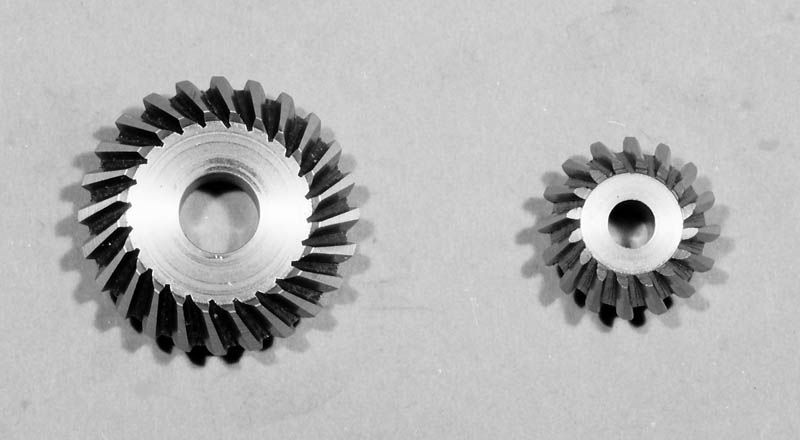
If your are just playing, I suggest that you cut a 1:1 set of 18 tooth gears to get the feel for it. This makes all the indexing angles even numbers and a multiple of 5 degrees. You can even do this with a spindex. The 1:1 ratio makes the blank angles 45 degrees which is easy to set up on the lathe.

Gail in NM
Edit: Before someone calls me on it, the formula I give for the the vertical offset is theoretically incorrect. However, the error is MUCH smaller than the resolution of any of the machine tools I have ever seen or used. On a 48 DP gear it less than 1/100,000 inch so there is no need to work with the correct but far more complicated formula.
 
Thanks Gail, I was wondering how to account for the difference in diameters on the gear teeth. Now I get it.

Kel
 
Hi Gail,
That last edit had me scratching my head so I had to check the books. The skew bevel gear Kozo is describing is a bit more complex than the simple version with zero offset of the shafts.

I also checked "Gear Design Simplified" and the rule given for the offset is 1/4 of the circular pitch at the small end which is the same as the formula you gave. Circular Pitch = Pi/Diametrial Pitch or CP=Pi/DP.

So as you said the rule for the offset is CP/4 or Pi/4*DP.

The difference in the 2 formulas might be calculator buzz as it is a really tiny amount.

Dan

Edit: With a bit more thinking.... the difference is most likely the fact that the circular pitch is measured allong the pitch circle and the mill spindle offset is a straight line so there is a very slight difference in length.
 
Dan,
I should have probably not even put that edit note in, but it seems that there is always someone who wants to argue when I make any simplification. So the disclaimer was added.

You are right. The error comes from the small difference between the circular pitch and the straight line and that will vary with the number of teeth. The fewer the number of teeth the larger the error. For any reasonable number of teeth, that is the minimum number that can be cut with an involute cutter, the error is too small to worry about.

For anyone who might be interested, the true vertical distance that we should be moving is:

VertDistance = N/(2*PD) * Sin(360/(4*N))
where N= the number of teeth in the gear.

Gail in NM
 
I have never cut any type of bevel gears, so this is all a learning experience to me.

Very interesting.


kcmillin said:
I'm not sure what the difference between skew bevel gears and bevel gears is.

Is a skew gear when the pinion is not inline with the center of the ring gear?


Kel, here is a picture of what the skew bevel gears look like. As you can see the teeth are in just a little different orientation than the common bevel gears.


Hiraoka9aSkewBevelGears.jpg
 
Ian
I belive this book is still copyrighted, therefore it is stealing if downloaded

Please correct me if incorrect.

Gordy
 
Back
Top